Embedded System Evolution in IoT System Development Based on MAPE-K Loop Mechanism
Abstract
Embedded systems including IoT devices are designed for specialized functions; thus, changes in functions are not considered following their release. For this reason, changing functions to satisfy the requirements of IoT systems is difficult. In this study, we focus on updating existing embedded systems without modifying them. We investigate the design of new functions and their implementation with limited resources. This paper describes an evolution mechanism for updating the functionalities of existing embedded systems. The evolution mechanism uses a control unit that is deployed outside the embedded system. To guide the steady implementation of the evolution mechanism, we define an evolution process that effectively uses the state machine diagram at the design time and runtime to update the embedded systems. The programming framework implemented in this study supports the evolution process. We evaluate the evolution mechanism based on the results from two experiments. The first experiment involved applying the evolution mechanism to a cleaning robot, this demonstrated that the evolution mechanism systematically enables the injection of new functions into an embedded system in the real world. The second experiment, on the probabilistic model checking, demonstrated that the mechanism provides almost the same performance as the ordinary embedded system with an improved robustness.
Index Terms:
Internet of Things (IoT), embedded systems, system/software evolution, state machine diagram, MAPE-K loop, self-adaptive systems.I Introduction
IoT systems are developed by assembling various components, including sensors, devices, IoT clouds (software components), edge components, and user interfaces. Existing embedded systems are expected to be used as components of IoT systems for their efficient development. Embedded systems are usually designed to provide specific services. To provide these services efficiently, hard limitations are imposed on the hardware/software of the embedded systems. Such limitations prevent the embedded systems from being updated after their release. This characteristic sometimes yields negative effects to the development of IoT systems. When developing IoT systems, connecting sensors with devices is often required to incorporate a new monitoring function [1]. However, when we use embedded systems as devices in an IoT system, their lack of flexibility makes it difficult to connect these devices.
In this study, we address the issue related to the difficulty in updating embedded systems. We regard this issue as a problem in the system/software evolution [2] of embedded systems. We mainly focus on updating existing embedded systems without modifying existing functions and components. We use a control loop to add new functions to embedded systems by changing the system control flow. The control loop [3, 4, 5] is a promising approach for creating automated systems. In particular, the MAPE-K loop [6] has attracted attention owing to its autonomous management of information systems [7]. We expect that the MAPE-K loop mechanism to be compatible with IoT activities at various levels, namely monitoring, controlling, optimization, and autonomy [8].
This paper describes an evolution mechanism that supports for updating the functionalities of embedded systems. The evolution mechanism uses a control unit, which is deployed outside the embedded system. The control unit is constructed based on the MAPE-K loop. A programming framework developed in this study aids in constructing the control unit. We define an evolution process that supports the system evolution from the early stage of the system design phase to the implementation phase. The evolution process uses the state machine model to detect and handle changes between the original and new versions of the system. The state machine models of the two versions are used by a MAPE-K loop component at runtime.
The main contributions of this paper are as follows:
- (1)
Evolution mechanism for embedded systems: The mechanism enables the evolution of embedded systems without modifying embedded systems. This mechanism uses an event converter to control an embedded system to behave as a new embedded system.
- (2)
Evolution process: This process systematically implements the evolution of embedded systems using the evolution mechanism. This process uses the state machine models to design new functions and implement evolution to the mechanism.
- (3)
Programming framework: The framework aids in implementing the evolution in embedded systems more steadily. In particular, the framework helps us construct the event converter by providing useful APIs. This framework is developed based on our previous framework [9].
- (4)
Experimental evaluation: We apply the mechanism, process, and framework to a cleaning robot evolution scenario in the real world to evaluate the effectiveness of the evolution process. We also evaluate the performance and robustness of the proposed mechanism using the probabilistic model checking technique.
The remainder of this paper is organized as follows: Section II presents the background of this study, including the state machine diagram and MAPE-K loop. Sections III to V describe the design, implementation, and addition of new functions to embedded systems using an evolution example of a lighting bulb system. Section VI reports the results of applying the framework to a cleaning robot evolution scenario and verifying the performance and robustness of the proposed evolution mechanism. Section VII discusses of our approach based on the results, Section VIII summarizes related work, and Section IX concludes this paper and outlines future work directions.
II Theoretical Background

II-A State Machine Diagram/Model
A state machine diagram is a graphical model in the Unified Modeling Language (UML) [10]. The basic state machine diagram is a finite automaton in computer science. Figure 1 presents an example of a state machine diagram, whose main elements are states and transitions. The state machine diagram forms a graph consisting of states and transitions that connect the states. A state is a situation in the life cycle of an object, whereas a transition represents the movement from one state to another. Each transition can be labeled as an event that causes a transition.
The state machine diagram is used extensively in embedded system development [11]. A main reason for this is that the event-driven architecture provided by the state machine diagram allows us to describe more flexible patterns of control than any sequential system [12]. The diagram can explicitly define the handling of events that occur in each state. Unlike static UML diagrams including the class diagram, the state machine diagram can represent the dynamic behaviors of the system. Hereafter, we refer to a model described by the state machine diagram as a state machine model.
II-B MAPE-K Loop


The MAPE-K loop [6] was originally developed as a mechanism for autonomous software systems, such as self-adaptive systems. Figure 2 overviews the MAPE-K loop mechanism [6]. The mechanism aims to control a software system by continuously executing four steps (components), known as monitor, analyze, plan, and execute, which form a loop. A target system is monitored to determine whether problems have occurred using logs and sensors at the monitor step. If a problem is identified at the analyze step, the mechanism attempts to determine the cause of the problem. Thereafter, at the plan step, actions are planned to solve the problem according to the analysis results derived from the analyze step. Finally, the actions planned in the previous step are performed at the execute step. Subsequently, the MAPE-K loop mechanism repeats the activities by monitoring the results of the execute step. The MAPE-K loop also includes a complementary component known as knowledge, which manages the data to be shared among the four components. The shared knowledge contains data such as topology information, historical logs, and policies. The aim of this type of loop structure is to identify and handle system problems efficiently.
III Embedded System Evolution
This paper describes an embedded system evolution mechanism that can update the functionalities of embedded systems. Owing to their hardware constraints and enhanced reliability, embedded systems generally exhibit less flexibility for evolution. To overcome this problem, we adopted an external approach using additional hardware for the evolution. Figure 3 depicts the system architecture of the evolution mechanism. Using an external approach that uses additional hardware (the external device in Figure 3), additional memory or storage space for implementing new functions to be added can be obtained. In this mechanism, the event converter plays the central role in controlling the new embedded system. We focus on the event-driven structure of the embedded system. The event converter changes incoming events sent from the controller appropriately to control the behavior of the embedded system and satisfy the new requirements.
We use the MAPE-K loop structure to construct an event converter. The MAPE-K loop monitors incoming events and handles the events properly according to the original and newly updated state machine models. The MAPE-K loop enables the handling of events automatically and asynchronously. A programming framework can be used to construct the event converter based on the MAPE-K loop structure. To guide the implementation of the evolution mechanism, we also define the evolutionary process, which encompasses the design and implementation phases of the development. The state machine model is the key model in the evolution process. The model is compatible with the design and implementation method of updating existing embedded systems.

We consider the evolution scenario of a light bulb system to explain the evolution process. Figure 4 depicts the application domain of a light bulb system. The embedded system, i.e., the light bulb system, receives commands corresponding to events from an (external) controller, which is a power switch in this scenario. The system responds to the commands (events) from the controller. The communication interface sends/receives events between the controller and embedded system using physical media, such as ethernet, serial cables, radio communication, and infrared rays. The controller, which is a power switch, switches light off and on. Figure 5 presents the state machine model of the light bulb system. The light bulb system has two modes: off and on. When the system receives a switch signal as an event, the state moves from off to on, and vice versa.
We envision the following evolution scenario.
Evolution (add a new color mode): The lighting system should turn on the light in the daylight color, which is implemented in the initial version, and in the incandescent lamp color, which is a new color tone. The colors can be changed by pushing the same switch. The daylight color light can be turned off without providing the incandescent lamp color by waiting two seconds after pushing the switch.
Although this evolution scenario is simple, it requires the fundamental problem encountered when updating the functionalities of existing embedded systems. Thus, new functions must be designed while combining the original and new functions.
IV Design Phase
This section describes the design of the evolution of an embedded system in our mechanism. In our evolution process, new functions for embedded systems are designed using state machine models. This section also explains how to handle the changes using the MAPE-K loop mechanism.
IV-A Design Using State Machine Model
As this study focuses on the evolution of embedded systems, we assume that embedded systems cannot be designed from scratch. Furthermore, we assume that a state machine model is available for the current version of the system. If the state machine model does not exist, it should be constructed for the original (current) version of the system. Figure 5 presents the state machine model for the original version of the light bulb system in our example. We revise this model to incorporate new functions.

As modifying the equipped functions of embedded systems is difficult, the existing states that are implemented, such as the functions associated with the off and on states in the light bulb system, should not be changed. These states are generally related to hardware resources. If the existing states are modified, the part to be modified must be identified at the software layer and hardware layers. This is one of the most difficult tasks in the evolution of embedded systems. Therefore, we avoid the modification of existing functions and associated states.
During the design phase, we focus on the event-driven structure. Most embedded systems are event driven [11], meaning that they continuously wait for internal or external events, which may include time triggers and user actions such as button pushes. The event converter of our evolution mechanism extracts incoming events and creates new events. To construct the event converter, new events and states should be identified and added to the state machine model. The new events and states must be added to the original state machine model without removing existing states. New functions should be described by adding states and transitions for reaching the states. Such modification enables new functions to be added to the embedded system without changing the original version.
In a state machine model, a system (Sys) is represented using a finite number of events (), states (), and transitions (). The next state is defined using the current state and an upcoming event. This transformation for defining the next state is known as a transition, which is a member of . The system can be represented as a three-tuple:
where E, S, and T are expressed as follows:
Using this notation, the state machine model for the original light bulb system can be described as follows:
We evolve the light bulb system to react to the new requirements described in Section III. The original system has two states: off and on. To handle the new requirements, a new function for providing a new color tone must be added, which should be invoked by pushing the switch.
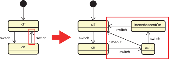
As new functions must be added without modifying the existing states, events, transitions, and new states are added to the original state machine model to construct the new state machine model. A solution for our evolution scenario is to add two new states, wait and incandescentOn, to the model. The former state provides a conditional branch for whether the system should change the light to the incandescent color or should turn the light off, whereas the latter represents the state to provide the incandescent color light. Figure 6 depicts the changes in the state machine model that is used to handle the evolution. The right model in Figure 6 represents the new state machine model. The timeout event embedded in the model allows users to select whether the light is changed to an incandescent color or is turned off. In our example, two seconds after the state is changed to wait, the internal timer executes this event.
We define two conditions that are imposed on the new state machine model. Both conditions guarantee that the new system does not destroy the original functions related to the individual states and interface of the embedded system.
Definition IV.1
Necessary conditions of new state machine model: The new state machine model should have a set of events () and states () that satisfy both of the following conditions.
- •
Condition 1:
- •
Condition 2:
These conditions guarantee that the states and events of the original system are not destroyed. New states and events should be added if necessary. However, transitions can be added as well as modified from the original state machine model. In our example, the new light bulb system can be defined as complying with the following conditions:
IV-B Design of Event Converter
As illustrated in Figure 3, the event converter plays a central role in the evolution mechanism. We focus on the event-driven structure of embedded systems. As indicated in Figure 4, events are usually sent from the controller to the embedded system. In our evolution mechanism, the events sent from the controller are intercepted by the event converter. The event converter, which is constructed based on the MAPE-K loop mechanism, generates a new event that is determined from the state machine models and event that the converter received. The converter may invoke a new function implemented on the external device instead of generating a new event.
When an existing function of the embedded system should be performed, the converter sends events to the embedded system to invoke the existing function. However, the converter should not send events to the embedded system when a new function implemented on the external device should be performed. Therefore, the event converter must determine whether the new system provides an existing or new function. The converter generates events to be sent to the embedded system if necessary. The event converter uses two state machine models, the original and new state machine models, to generate events. As this converter should behave independently from the controller and embedded system, we construct a converter based on the MAPE-K loop. In the following, we explain how events are generated using the MAPE-K loop mechanism.
The components of the MAPE-K loop have individual tasks, as follows:
- •
Knowledge: includes the original and new state machine models and manages their current states.
- •
Monitor: receives events sent from the controller.
- •
Analyze: verifies whether the coming event is acceptable at the current state.
- •
Plan: generates a plan, which consists of a list of events for invoking existing functions and commands to invoke new functions if necessary.
- •
Execute: sends events to the embedded system or invokes new functions.
The event converter determines the new actions according to Algorithm 1. If the monitor component observes the event occurrence (line 3), the analyze component probes whether the event is acceptable at the current state (line 5). The analyze component determines whether the system should use an existing or new function (line 7). The plan component plans the next action based on the analysis result (lines 8 and 11). Finally, the execute component performs the action determined by the plan component (line 14) and updates each state to the next state (lines 9, 10, and 12).
For the light bulb system, the initial state is the off state in both the original and new models. If a event occurs, the event converter generates a event. The next state, i.e., the on state, which is the return value of the nModel.getNextState(off, switch) method, exists in both the original and new state machine models (Figure 6). As the state exists in both models, the converter uses an existing function of the embedded system. In this case, the event converter generates the same event as the received event without changing it ( in Figure 3). We consider the situation in which the event occurs at the incandescentOn state in the new model. The next state, i.e., the return value of the nModel.getNextState(incandescentOn, switch) method, is the off state. The off state exists in both the original and new models. To use a function provided by the existing embedded system, the converter must send events to the system to change the system state; that is, the original model state. The current state in the original model is the on state. Therefore, a event is sent to the embedded system, and the state is changed from on to off; that is, the converter sends (the switch event) as to the embedded system without any changes.
Next, we consider the situation in which the event occurs at the on state in the new lighting bulb system. The next state is wait, which is the return value of the nModel.getNextState(On, switch) method. This state does not exist in the original model, but it exists in the new model (Figure 6). In this case, new functions are used on the external device. Therefore, the event converter invokes new functions that are associated with the wait state without generating any events, and updates the current state of the new model.
When the timeout event arrives at the wait state in the new light bulb system, the next state, the return value of nModel.getNextState(wait, timeout), is the off state. As the state exists in both models, the existing functions of the embedded system associated with the off state are used. The converter sends the switch event to the system to use the functions provided by the existing embedded system.
V Implementation Phase
This section describes the programming framework for implementing the event converter based on the MAPE-K loop mechanism. We explain the implementation of a new function corresponding to a new state in the new state machine model and the use of the functions from our framework.
V-A Event Converter Implementation
V-A1 State Machine Models
The event converter uses two state machine models as behavioral models to extract and handle changes between the original and updated systems. Our framework assumes that state machine models are constructed using Astah [13], which is a UML modeling tool. Astah can export models into the XML metadata interchange (XMI) format, which aids in exchanging UML models across different UML tools. By parsing state machine models in XMI format, the event converter can identify the events to be detected so that it can determine a transition for the next state.
V-A2 External Device
Our evolution mechanism uses an external device in which the event converter is deployed. The following mandatory requirements apply to the external device:
- 1.
The device should have a communication mechanism with the embedded system such that the event converter can send events to the embedded system.
- 2.
The device should be as small as possible to satisfy the physical constraints of the embedded system.
To satisfy these requirements, we deploy an event converter on a Raspberry Pi [14]. Raspberry Pi is a small device; however, because it can use an operating system such as Ubuntu, various programs can run on it. It also has several interfaces such as GPIO pins and USB ports, to communicate with other devices. For these reasons, Raspberry Pi is a suitable device for deploying an event converter.

V-A3 Programming Framework for Event Converter
Our programming framework aids in implementing the event converter based on the MAPE-K loop mechanism. The framework provides APIs for developing MAKE-K loop mechanisms, as indicated in Algorithm 1. A developer mainly implements two parts using this framework: the code for monitoring events sent from the controller, and the code for sending events to the embedded system or for calling new functions. Thus, the two parts correspond to the interfaces of the event converter.
We use Java to execute multiple components in parallel, as it is a language that provides multi-thread programming. We previously implemented a lightweight programming framework for operations on real-world hardware [15] [16]. This framework assumes that a system is developed based on a component-based structure [17], in which components can be added, removed, and replaced dynamically.

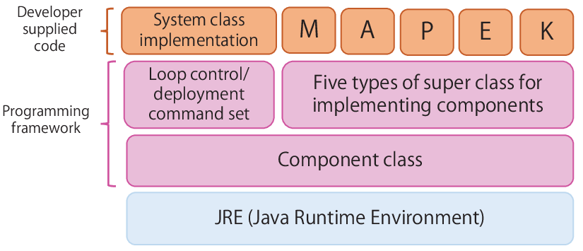
Figure 7 presents the programming model of the proposed framework. This framework provides the concurrent execution of classes, which are implemented as extensions of the Java Thread class. Figure 8 depicts the architectural configuration of the event converter, which is implemented based on the MAPE-K loop mechanism. The knowledge component is connected to the other components to share the data, including the state machine models. Figure 9 displays a class diagram of the programming framework. We introduce two main groups of classes that provide useful APIs. The first group consists of super-classes for implementing five types of MAPE-K loop components. We can focus on implementing individual concerns by inheriting these super-classes. The second group contains the SystemEventConverter class, which controls the MAPE-K components implemented by inheriting one of the super-classes belonging to the first group. Each monitor, analyze, plan, and execute component generally starts its activity after the previous component finished its activity. The threads of their components are controlled by the SystemEventConverter class, in the order of monitor, analyze, plan, and execute. Once the execute thread completes, the MAPE-K loop moves repeatedly from the monitor thread. The SystemEventConverter class handles thread processing and data flow, as illustrated in Figure 8. By inheriting and using these classes, a developer can implement the event converter without considering the thread synchronization and data flow of the MAKE-K loop process.
The event converter is deployed on the external device. The framework provides a command set for deploying the event converter with the MAPE-K loop components. Table I lists commands that are provided. Among these commands, the control commands, such as start and stop, change the execution state of the MAPE-K loop components, whereas the status command indicates the current status of the MAPE-K loop.
| Command | Description |
|---|---|
| start | Start the MAPE-K loop process. |
| stop | Stop the MAPE-K loop process. |
| status | Show the current status of the MAPE-K loop. |
| exit | End the MAPE-K loop process. |
V-A4 Development Steps
The event converter is implemented and deployed according to the following steps:
(1) Behavior coding: The components of the event converter should be implemented as MAPE-K components. These components can be implemented by extending the super-classes and overriding the methods in the super-classes provided by the framework. For example, the class for event monitoring can be implemented by inheriting the Monitor super-class and overriding its getEvent method. The getEvent method should end by returning an event that is handled by the method. The result of the monitor component process is passed to the analyze component as an argument for the analyze method. The processes of the analyze and plan components, which are indicated in Algorithm 1, have already been implemented in parent classes; therefore, we do not need to change these classes. New functions corresponding to new states in the new state machine model should be implemented in this step.
(2) Component configuration: The instances of the implemented components are registered in the list defined in SystemEventConverter class using add* methods (Figure 10). After registering the instances, the build and start methods connect components and start the MAPE-K loop, respectively. In Figure 10, the MonitorEvent class is a subclass of the Monitor parent class. An object of the MonitorEvent class is registered to the SystemEventConverter object using the addMonitor method.
(3) Deployment of event converter: New functions corresponding to new states in the new state machine model should also be registered. These new functions are called by a method that is included in the Knowledge class (Section V-B). After creating an executable file, which is a jar file, developers deploy the event converter and control the MAPE-K loop by executing the commands listed in Table I.

V-B Implementation of New Functions
If a function corresponding to a new state is simple and not large, the function should be implemented as a single class. Otherwise, we first break the corresponding state into sub-states; that is, the state is replaced with a composite state. In this case, we implement each sub-state as a concrete state in the state pattern of the design patterns [18]. To create independence between the new state and the others; that is, between the new function and the others, we can implement the function in the control loop structure. In our previous studies [16, 19], we developed a software evolution process based on control loops. The process constructs a system by combining control loops, which facilitates the localization of the impact of changes in the corresponding control loops. The process also enables us to reduce the effort required for finding and revising changes, which is a costly task in the software evolution process.
When the event converter starts, it creates a hash table for the state machine models. All of the transitions available from the original and new state machine models are registered in the hash table in the knowledge component. The hash table is used by calling the getTransition method, as indicated in Algorithm 2, in the plan and execute components. The converter determines the next action based on the current state and incoming event. The Knowledge class provides the putTransition(s0, s1, action, ) method for registering transitions. A transition is registered as a four-tuple: the current state (s0), incoming event (), next state (s1), and function to be called ().
VI Experiment


To evaluate the proposed evolution mechanism, we conducted two experiments. The first experiment handles an evolution of a cleaning robot in the real world (Exp. 1), and the second evaluates the performance and robustness of the mechanism (Exp. 2).
VI-A Exp. 1: Evolution of Cleaning Robot
We applied the evolution mechanism to a cleaning robot as a real embedded system to evaluate its applicability and effectiveness. According to the evolution process, we first defined the original and new state machine models for the cleaning robot. Thereafter, we implemented an event converter and new functions using our framework and deployed them on an external device. Finally, we verified whether the evolved robot behaved correctly by following the new state machine model.
In this experiment, we used a Roomba [20] as the cleaning robot and Raspberry Pi as the external device. The Roomba provides a serial port and serial interface [21]. The event converter receives and sends events via a serial port provided by the Roomba. Figures 11 and 12 present a snapshot and the system architecture of the cleaning robot used in this experiment, respectively. The cleaning robot has two main functions: clean and spot. When the CLEAN button provided by the robot is pressed, the robot navigates to clean the field automatically. When the SPOT button is pressed, the robot intensely cleans a localized area by spiraling and then stops cleaning when it returns to the starting point. Figure 13 depicts the original state machine model for the cleaning robot. The robot cleans during the clean state. The clean state is changed to the on state when the robot receives a clean event invoked by pressing the button. The robot spot cleans during the spot state. When the robot completes the spot cleaning, the state is changed to the on state by receiving the endSpot event sent by the robot itself.
We envision the following evolution scenario.
Evolution (move to the remote starting point): The cleaning robot starts spot cleaning after it arrives at a starting point. When the robot recognizes the starting point using a USB camera, the robot moves to that point.
VI-A1 Design
We begin with the definition of the original and new state machine models. The new state machine model satisfies the new requirements described in the evolution scenario. In the design of the new system, we did not change existing states: the off, on, spot, and clean states. The system behavior of the robot was changed by adding new events and states. We used existing events provided by the cleaning robot, the clean, spot and endSpot events, without using additional buttons for new external events. To avoid making the existing functions unusable for mapping existing events to new states, we added new transitions to the existing states. This additional path enabled the preservation of the existing functions. We added two new states: move for moving to a starting point and spotWait for providing a detour path using the original spot mode. Figure 14 depicts the changes in the state machine model. The new event timeout enables the selection to start spot cleaning or to finish cleaning; the arriveSpot event informs the robot of the arrival.

VI-A2 Implementation
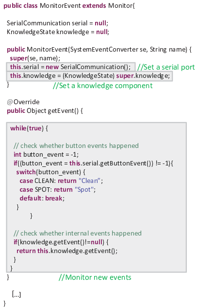
We developed an event converter using the proposed framework. In particular, we implemented two classes for the converter: for monitoring events and sending events. The former is the MonitorEvent class that inherits the Monitor super-class, as illustrated in Figure 15. The converter should detect the CLEAN and SPOT button events through the Roomba serial interface. Therefore, we used an external SerialCommuniation class for the Roomba serial interface. We implemented the event monitoring process by overriding the getEvent method, which returns a new event when it arrives.
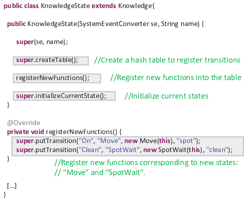
To implement new functions, two new states, move and spotWait states, were added to the original state machine model in the design phase. We implemented two functions relating to the two respective states and then registered the functions to the event converter such that the new functions can be called from the event converter. We implemented the function relating to the move state using a control loop structure. The control loop mechanism provides high independence such that the functions can be separated from the other functions and event converter. This mechanism is also beneficial for executing actions in parallel with less dependence. However, we implemented the function corresponding to the spotWait state as a single class because the action is not complicated. Figure 16 presents the KnowledgeState class, which extends the Knowledge super-class. The constructor of the class has a transition hash table, the contents of which are automatically generated by parsing the state machine models. By overriding the registerNewFunctions method, new functions corresponding to the new states were registered to the knowledge component.
VI-A3 Results
After deploying the event converter, new functions, and two state machine models on the external device, we started the event converter using the commands listed in Table I. Listings 1 and 2 present the logs of the cleaning robot execution. First, the CLEAN button was pushed (lines 1 to 13 in Listing 1) to turn on the cleaning robot. When the SPOT button was pushed, the cleaning robot invoked the new function (lines 26 to 28) and moved to the marked point (lines 30 to 33), which was the expected behavior of the evolution scenario. After the cleaning robot arrived at the starting point (lines 31 to 33), the robot suitably provided spot cleaning (lines 35 to 62). In the other execution (Listing 2), when the CLEAN button was pushed twice in the clean state (lines 1 and 18), the robot started the original spot cleaning (lines 28 to 33). We observed that the new functions were successfully added to the cleaning robot without degrading functionality.
indicates that the robot executed a new function.
the robot executed an original function following its evolution.
VI-B Exp. 2: Performance and Robustness
We evaluate the performance and robustness of the proposed mechanism using the probabilistic model checking technique [22]. Model checking is known as an effective technique for developing critical applications [23]. Probabilistic model checking verifies models with state transitions annotated by probabilities or transition rates. The technique determines whether QoS requirements specified in temporal logics are satisfied by the model. In this study, we used PRISM [24], a probabilistic model checker, for this experiment. We constructed continuous-time Markov chain (CTMC) [25] models and defined two QoS requirements:
- •
performance: the process of the embedded system should finish as fast as possible.
- •
robustness: event loss caused by timing errors should be as small as possible.

We adopted a modeling style used in various examples, such as [26][27]. Two CTMC models are used in Exp. 2; the first model is for the baseline mechanism, which corresponds to an ordinary embedded system, as illustrated in Figure 17 (a); the second model is for the baseline mechanism, as illustrated in Figure 17 (b). Listing 3 shows the CTMC model for the proposed mechanism, corresponding to model (b) in Figure 17.


Exp. 2. The controller illustrated in Figure 17 is not explicitly described
in this model.
The following parameters, all of which were defined in Listing 3, were used in this experiment.
- •
st_max = 20 (line 4): State path length required to reach the final state.
- •
event_arrive = 1/2 (line 6): Inverse of the average time interval between event arrival. It means that the average time interval between event arrival is 2 s.
- •
emb_internal_process = 1/1 (line 7): Inverse of the average action time of the embedded system.
- •
conv_internal_process = 1/0.25, 1/0.5, 1/0.75, or 1/1 (line 8): Inverse of the average conversion time. In this experiment, we used four values for the average conversion time: 0.25, 0.5, 0.75, and 1 s.
Because the average action time of the embedded system is 1 s, the average conversion time represents the ratio comparing with the action time of the embedded system. For example, when the average conversion time is 0.5 s, the converter is twice as fast as the embedded system.
To evaluate the two QoS requirements, we used the following two properties:
- •
P=? [F [T,T] emb_st = st_max]: This property calculates the transient probability of the state of the embedded system being the final state (the 20th state). We can use this property for evaluating the performance of the mechanism. If the probability increases to 1.0 faster, the mechanism can reach the final state faster, i.e., the mechanism can finish tasks faster. - •
R{"lost"}=? [C<=T]: This property is used for the robustness evaluation. TheRoperator represents the reward-based analysis. In particular,C<=Tcorresponds to the reward cumulated along a path until timeThas elapsed. Reward “lost” is defined in lines 48 to 51 in Listing 3. This reward increases when the converter or embedded system fails to receive events. Therefore, this property calculates the expected number of lost events. We use this property for the robustness evaluation.
Figures 18 and 19 illustrate the results. Figure 18 shows the performance evaluation results when changing the conversion time. From this graph, we determined that the proposed mechanism provides similar performances as the baseline mechanism when the conversion time is sufficiently faster than the action time of the embedded system (converter=0.25 in the graph). Figure 19 shows the number of events lost. From these results, we determined that the proposed mechanism improves the prevention of the events lost when the conversion time is faster than the action time of the embedded system. These results show that the proposed mechanism performs well and is sufficiently robust when the event conversion is sufficiently faster than the action time of the embedded system.
VII Discussion
We discuss our evolution mechanism from design, applicability, implementation, and system evolution perspectives.
VII-A Design
Our evolution mechanism uses original and new state machine models to add new functions to an embedded system. When the event converter determines that the next state exists in the original model, the converter causes the embedded system to use the original function. If the next state does not exist in the original model, the converter executes a new function associated with the transition to the new state.
The current framework can only handle flat state machine models, which do not contain hierarchical or orthogonal structures. We should translate a state machine model containing hierarchical or orthogonal structures into a flat model according to the equivalence relationship described in [28]. The extension of the framework for considering the hierarchical and orthogonal structures is planned as the next step of our study.
The new state machine model must be carefully designed to avoid introducing unexpected transitions and a lack of necessary transitions. Introducing a mechanism to support the reachability analysis is beneficial at design time to not provoke system degradation. A model checking technique for verifying the correctness properties of state machine models can solve this problem. This technique will aid in revising the models or disabling certain functions more safely.
Furthermore, the evolution mechanism uses an external device to deploy and execute new functions. When a new function uses an existing function implemented in an embedded system, the state of the embedded system may change incorrectly. This situation should be carefully considered. In the cleaning robot scenario, the new function was able to be implemented without influencing the embedded system. However, when a new function changes the state of an embedded system, the new system must not change the state of the embedded system unintentionally. This problem can be solved in certain cases. Two types of behaviors and their corresponding new states should be prepared: the states that affect the embedded system and states that recover the state of the embedded system. When implementing parts of new functions corresponding to the former states, we add additional features to maintain the current state of the embedded system. The latter states restore the state of the system after the new functions were executed and change the state of the embedded system.
Formal specifications can be applied in the design phase to connect the design model with the implementation code. For example, VDM++ [29] can describe specifications based on object-oriented design. VDM++ handles explicit descriptions that explain how functions are implemented and implicit descriptions that outline what is required in the functions. After designing the state machine models, these specifications may aid in conducting a stepwise refinement of the new functions. Domínguez et al. [30] provided a systematic review of code generation from state machine specifications. The generation techniques described in the survey paper can be used; however, because we use state machine models not to develop the system itself but enable the event converter to identify the differences from the original behavior, the application of the technique will be partial.
VII-B Applicability & Implementation
Although certain embedded systems have communication interfaces, many embedded systems are closed from the outside. In this study, we assumed that embedded systems have communication interfaces, such as APIs or ports, to receive events from the event converter. In the cleaning robot scenario, a serial port was available for sending events to the robot. However, when an embedded system does not provide any communication interfaces, a new mechanism must be constructed to send events from the event converter. Even if an embedded system does not have communication interfaces, we can still control the system. One solution is to develop a hardware device that affects the user interfaces of the embedded system, such as a device that pushes a button at the correct time. Another solution is to change the environment of the embedded system. For example, an air conditioner being operated when an external device reduces or increases the temperature around the sensor of the air conditioner. These actions play the role of sending events to the embedded system.
Our framework does not restrict the implementation style of the new functions in the evolution process. This enhances its affinity with other systems and applications, such as ROS2 [31], which is the newest version of the Robot Operating System (ROS) [32]. Furthermore, this enables us to implement new features on additional devices. For example, many external IoT devices can be used for this purpose.
The results of the cleaning robot experiment in Exp. 1 demonstrate the applicability of the evolution mechanism. As shown in Exp. 2, the suitable event converter improves the robustness of an embedded system by preventing event loss. It is caused by the fast event converter successfully receiving events from the controller. Because most embedded systems require a significant amount of time to provide their services, they tend to miss subsequent events. This is an advantage of the proposed mechanism.
Most embedded systems have a certain degree of time constraints. First, the system performance must be considered. The performance evaluation in Exp. 2 verifies that the proposed mechanism provides similar performance to a vanilla embedded system when the event conversion is sufficiently faster than the action of the embedded system. Because the action time of an embedded system usually includes the time to provide services using hardware, the event conversion time is significantly faster than the time that the embedded system requires. Second, strict time constraints imposed on an embedded system must be continuously observed. Our current event converter does not contain mechanisms for verifying time constraints. We previously reported an initial study on a programming framework that handles time constraints at runtime [33]. The framework is for developing real-time systems and dynamically uses the model checking tool UPPAAL to verify time constraints. We can enhance the support for handling time constraints by unifying this framework and the event converter.
VII-C System Evolution
When considering the system evolution, the system maintainability should be addressed. In object-oriented development, a system is developed by combining objects or components. Object-oriented development generally improves maintainability; however, the amount of code tends to increase. This characteristic opposes the requirement for embedded systems; that is, software and hardware resources should be as small as possible. Using an additional external device offers an advantage in this regard. New functions can be implemented and executed without using limited hardware resources on the embedded system. The external approach also improves the maintainability of embedded systems. System evolution usually increases the complexity of the code; however, implementing new functions in the external device maintains existing code from becoming more complex. The comparison between the original and new state machine models helps developers identify the differences visually. We proposed a software evolution technique [19] that localizes changes into components using goal modeling. This technique will also help separate new function modules from existing implemented functions. The deployment support of our framework, that is, the commands for controlling new functions and their deployment, is also effective for system evolution.
VIII Related work
This section summarizes related work in terms of design methods for embedded systems, reprogramming, firmware updating, frameworks using UML diagrams, and IoT system development.
VIII-A Design Methods for Embedded Systems
Various design methods have been proposed for embedded systems. Herrera et al. [34] proposed the COMPLEX UML/MARTE design space exploration methodology for embedded systems. This approach is based on a combination of model-driven engineering, the electronic system level, and design exploration technology. It uses the MAPERE profile, which offers a rich set of extensions specifically suited for the specification of embedded real-time systems. Lapalme et al. [35] proposed a .Net framework-based methodology for designing a new embedded system design tool. Apvrille and Roudier [36] defined a SysML-based model-driven development methodology for embedded systems, which focuses on the security properties of embedded systems in particular. Hegedüs et al. [37] defined a model-driven framework for design space exploration that analyzes implementation alternatives, which satisfies all design constraints to identify the most suitable design choice. These studies handled the development of embedded systems; however, the methods proposed in these studies were assumed to be applied in the (initial) development of embedded systems, and therefore, they did not address the evolution of embedded systems.
A solution to the resource problem in embedded systems is an external approach that uses additional hardware. Chung and Subramanian [38] presented an architecture-based semantic evolution of embedded systems. They focused on embedded systems that can be remotely controlled and identified four architecture types for this purpose: the 3Rs (rework, reload, and reboot), stored data, rule-based, and runtime module generation types. They used the NFR framework [39] to select the suitable semantic evolution and its corresponding architecture type. Berthier et al. [40] proposed a global resource control approach based on a centralized view of the device states using a Boolean Mealy automata diagram. Although their control layer was similar to our event converter, they focused on the synchronous control of embedded systems to optimize global resource, and not the evolution of embedded systems.
VIII-B Reprogramming
Reprogramming, which is the act of changing a program, is an effective method for adding new features to a system. In particular, the reprogramming of embedded systems is a long-standing problem in this field. Gay et al. [41] presented the nesC language, which supports the analysis of the system design by providing a programming model that incorporates event-driven execution and a flexible concurrency model. Furthermore, they developed the nesC compiler to perform whole-program analysis to reduce the resource consumption and improve the reliability. Shafi et al. [42] proposed a reprogramming scheme consisting of a patch known as Queen’s differential (QDiff). QDiff mitigates the effects of program layout changes and retains the maximum similarity between the old and new codes using similarity detection approaches. They focused on the lower-level problems of embedded system reprogramming, such as power, speed, downtime, and reliability.
Embedded systems are used extensively in IoT environments. Updating new features enables existing devices to be connected to one another when constructing IoT systems. The problem of adding new features to embedded systems is necessary for developing IoT systems and wireless sensor networks [43, 44, 45]. By reprogramming, attempts have been made to change the functionalities of the devices under resource constraints, such as energy, memory, and processing power, over time.
These approaches aid in reprogramming code implementations in embedded systems, whereas our evolution mechanism aims to ensure that the existing systems are not modified. This mechanism enhances the modularity of existing systems. Both a reprogramming technique and programming framework can be used in our evolution mechanism. The use of a reprogramming technique will help the framework communicate with the embedded system.
VIII-C Firmware
Firmware is software that controls hardware devices. Modern firmware is stored in EEPROM or flash memory, compared to old firmware architecture that was stored on ROM. Therefore, manufacturers can provide new features, revise bugs in their system, and protect users from security vulnerabilities through a firmware update. Such an update is performed via the USB or SD card and the Internet.
Mansor et al. [46] analyzed the security of a firmware update protocol for vehicles. Based on the results, they suggested several improvements in the protocols relating to safety and security measures. Jurkovic et al. [47] proposed firmware update mechanisms for many distributed embedded devices controlled by a centralized server. Their approach provides dynamic upgrades of software in a rapid, robust, and reliable manner via the Internet.
Secure firmware updates are one of the most important issues in the IoT environment. Asokan et al. [48] proposed a secure firmware update framework known as ASSURED, which provides a secure and scalable update for IoT systems. They considered realistic problems in large-scale IoT deployments while providing end-to-end security with enforceable constraints. Moreover, they decentralized heavy computational operations to external devices to place a minimal burden on the IoT devices. Lee et al. [49] proposed a blockchain-based secure firmware update methodology. When the firmware is updated, the embedded device downloads the latest software from a peer-to-peer firmware sharing blockchain network of nodes. Their approach allows vendors to provide new functionalities and patch vulnerabilities on embedded devices.
Taha and Mustafa [50] proposed a custom in-system firmware upgrading methodology using a serial peripheral interface (SPI). They focused on large-scale embedded systems that do not have interfaces to run programming, such as the universal asynchronous receiver/transmitter. They updated the firmware through the SPI. In the cleaning robot example, we used the SPI provided by the robot when new features were added. However, we used it to send commands corresponding to an event and not to upgrade the existing system.
The firmware ROS2 [31] provides libraries and tools to help software developers create robot applications such as hardware abstraction, device drivers, and package management. Furthermore, it provides many functionalities to create robots, owing to its open-software community and easy integration mechanisms based on self-programmed nodes. ROS enables robot applications to be created as well as the addition of new features using libraries that strongly wrap the hardware system.
Firmware update techniques are used to add new features to embedded systems, whereas our evolution mechanism adds features without modifying existing systems. Neither technique conflicts with the other. Our mechanism can be used after a firmware update and new functions can be added using firmware. For example, our framework can remotely send events and commands via ROS. Furthermore, our framework, in which an implemented new function module uses a firmware such as ROS, can be used as a library.
VIII-D Development Using UML Diagrams
Numerous studies that have used UML diagrams have been conducted in the software engineering field. Yang [51, 52] outlined various methods for updating software systems using UML models and XML files. UML and XML are used as components of model-driven development in various methods. When the code of a software system is modified, refactoring [53] is generally conducted to understand the code and localize changes. Similar to refactoring, model refactoring is used to restructure the design to improve its quality and reduce its complexity. Mens et al. [54] presented a model-driven software development tool that uses UML diagrams, including class, use case, and activity diagrams. Sunye et al. [55] presented a refactoring set and explained how the method can be designed to preserve the behavior of a UML model. Samek [11] presented a method for implementing the UML state machine model in C/C++. In general, UML diagrams cannot perform to their best potential without frameworks to implement the software systems efficiently based on these diagrams. These frameworks enable systems to be designed and software to be implemented more efficiently.
Kangas et al. [56] proposed an automated UML-based design flow in which modeling and design control were handled in a single framework. They extended the UML 2.0 profile for back-annotating verification and architecture exploration, which was known as the TUT profile. The information provided by the profile can aid a designer in making critical architectural decisions. Riccobene et al. [57] extended UML 2.0 for SystemC and multithread C to provide a development methodology. This approach helps software and hardware engineers improve the design flow of industrial embedded systems. The profile for SystemC enables the engineers to model resources and concurrency from a hardware perspective; the profile for multithread C allows engineers to model concurrency from a software perspective. Marinescu et al. [58] presented FUSE for modeling and implementing embedded software components. This method provides a unified programming environment that supports statechart specifications and Java translations. By describing statecharts directly, FUSE prevents a lack of synchronization between the model and generated code. FUSE also enables tuning and debugging of the model and code within the same programming model.
These techniques were proposed with frameworks for managing complex situations. The primary focus was on frameworks using diagrams that support the implementation phase of the initial development from the design phase. Our study complements this focus with the evolution aspect. Our method first revises an existing model and subsequently adds new functions to embedded systems using these models.
VIII-E IoT System Development
The IoT domain addresses issues focused on in this paper. Several frameworks and middleware for IoT systems have been proposed. Armando et al. [59] proposed middleware that can handle heterogeneous IoT devices. Junejo et al. [60] proposed a framework for enhancing the security of the system, which provides a trust-based behavioral monitoring mechanism. Cheng et al. [61] introduced a knowledge graph-based multilayer IoT middleware. The middleware aims to solve the communication gap problem and heterogeneous access problem of IoT systems. The aim of these studies is similar to our study in terms of addressing device management and enhancement of the connectability of devices; however, our study mainly focuses on the function update of devises, i.e., embedded systems.
Some studies have addressed the configuration and architecture of IoT systems. Cai et al. [62] proposed a rapid system development method using various service integration patterns. This method is based on Model-View-Controller (MVC) architecture. Sun et al. [63] provided an energy-aware routing algorithm that minimizes server energy consumption while considering bandwidth consumption. The algorithm is used for dynamic service function chain deployment. Huang et al. [64] proposed a service-oriented network architecture to support the effective management of 5G-enabled IoT systems. Bera et al. [65] designed a blockchain-based IoT-enabled smart grid architecture. We use an external approach for implementing embedded system evolution. We currently assume that an event converter is used for a target embedded system to be evolved; however, when we handle several devices in an IoT system, an event converter may be used for several devices.
Liu et al. [66] proposed a manual reverse engineering framework for discovering the communication protocols of embedded Linux-based IoT systems. We assume that the original state machine model exists or can be described. These original protocols and behavioral models are important for the appropriate incorporation of organizing IoT systems. Cheng et al. [67] defined a dynamic evolution mechanism of Internet-of Vehicles (IoV) community. The mechanism uses a graph-based model to drive dynamic evolution. The evolution mechanism does not handle the implementation of components; however, components should have flexibility in terms of changes not preventing evolution. Our mechanism will aid such an evolution in enhancing the flexibility of components.
IX Conclusions
To develop more fitting components for IoT systems, this paper describes an evolution mechanism for updating the functionalities of embedded systems. The mechanism uses a control unit, an event converter, which is deployed outside of the embedded system to update the system without modifications. A systematic evolution process and programming framework helps implement the event converter. Using the original and new state machine models, the event converter based on the MAPE-K loop structure appropriately sends new events to the embedded system and executes new functions on the external device. The results of the first evaluation conducted on a cleaning robot demonstrated that our evolution mechanism can provide a model-based system design and API-based implementation to realize the evolution of an embedded system without modification. The second evaluation verified the performance and robustness of the proposed evolution mechanism. Note that the suitable event converter improves the robustness of an embedded system by preventing event loss.
Future work includes the enhancement of the support for hierarchical and orthogonal state machine models. Towards the model-driven engineering of secure and safe embedded systems, the introduction of a verification mechanism to ensure the accuracy of behaviors using model-checking techniques is also planned. We believe our mechanism contributes to the efficient and assured evolution of embedded systems and development of IoT systems.
Acknowledgment
This work was supported by the JSPS Grants-in-Aid for Scientific Research (Grant Numbers 15K00097, 17KT0043, 20H04167), Telecommunications Advancement Foundation, and Asahi Glass Foundation.
References
- [1] R. Khan, S. U. Khan, R. Zaheer, and S. Khan, “Future internet: The internet of things architecture, possible applications and key challenges,” in 2012 10th International Conference on Frontiers of Information Technology, Dec 2012, pp. 257–260.
- [2] T. Mens and S. Demeyer, Software evolution. Springer-Verlag Berlin Heidelberg, 2008.
- [3] J. O. Kephart and D. M. Chess, “The vision of autonomic computing,” IEEE Computer, vol. 36, no. 1, pp. 41–50, 2003.
- [4] P. Oreizy, M. M. Gorlick, R. N. Taylor, D. Heimbigner, G. Johnson, N. Medvidovic, A. Quilici, D. S. Rosenblum, and A. L. Wolf, “An architecture-based approach to self-adaptive software,” IEEE Intelligent Systems, vol. 14, no. 3, pp. 54–62, 1999.
- [5] M. Shaw, “Beyond objects: a software design paradigm based on process control,” SIGSOFT Software Engineering Notes, vol. 20, pp. 27–38, January 1995.
- [6] IBM, “An architectural blueprint for autonomic computing third edition,” https://www-03.ibm.com/autonomic/pdfs/AC%20Blueprint%20White%20Paper%20V7.pdf.
- [7] D. Weyns, B. Schmerl, V. Grassi, S. Malek, R. Mirandola, C. Prehofer, J. Wuttke, J. Andersson, H. Giese, and K. M. Göschka, “On patterns for decentralized control in self-adaptive systems,” in Software Engineering for Self-Adaptive Systems II. Springer, 2013, pp. 76–107.
- [8] M. E. Porter and J. E. Heppelmann, “How smart, connected products are transforming competition,” Harvard business review, vol. 92, no. 11, p. 18, 2014.
- [9] S. Tsuchida, H. Nakagawa, E. Tramontana, A. Fornaia, and T. Tsuchiya, “A framework for updating functionalities based on the MAPE loop mechanism,” in 2018 IEEE 42nd Annual Computer Software and Applications Conference (COMPSAC), vol. 01, July 2018, pp. 38–47.
- [10] O. M. Group, “Unified Modeling Language (UML),” https://www.uml.org/.
- [11] M. Samke, Practical UML Statecharts in C/C++: Event-Driven Programming for Embedded Systems, 2008.
- [12] J. Rumbaugh, M. Blaha, W. Premerlani, F. Eddy, and W. Lorensen, Object-Oriented Modeling and Design. Prentice-Hall, Inc., 1991.
- [13] I. Change Vision, “Astah,” http://astah.change-vision.com.
- [14] T. R. P. Foundation, “Raspberry pi,” https://www.raspberrypi.org/.
- [15] H. Tsuda, H. Nakagawa, and T. Tsuchiya, “Towards self-adaptation on real-world hardware: A preliminary lightweight programming framework,” in 2015 IEEE 9th International Conference on Self-Adaptive and Self-Organizing Systems, Sept 2015, pp. 176–177.
- [16] H. Nakagawa, A. Ohsuga, and S. Honiden, “Towards dynamic evolution of self-adaptive systems based on dynamic updating of control loops,” in 2012 IEEE Sixth International Conference on Self-Adaptive and Self-Organizing Systems, Sept 2012, pp. 59–68.
- [17] J. Kramer and J. Magee, “Self-managed systems: an architectural challenge,” in Future of Software Engineering (FOSE ’07), May 2007, pp. 259–268.
- [18] E. Gamma, Design patterns: elements of reusable object-oriented software. Pearson Education India, 1995.
- [19] H. Nakagawa, A. Ohsuga, and S. Honiden, “A goal model elaboration for localizing changes in software evolution,” in 2013 21st IEEE International Requirements Engineering Conference (RE), July 2013, pp. 155–164.
- [20] iRobot Corporation, “iRobot,” https://global.irobot.com.
- [21] iRobot corporation, “Roomba interface,” http://www.irobot.lv/uploaded_files/File/iRobot_Roomba_500_Open_Interface_Spec.pdf.
- [22] M. Kwiatkowska, “Quantitative verification: Models techniques and tools,” in Proc. of the the 6th Joint Meeting of the European Software Engineering Conference and the ACM SIGSOFT Symposium on The Foundations of Software Engineering (ESEC-FSE 2007), ser. ESEC-FSE ’07. New York, NY, USA: Association for Computing Machinery, 2007, p. 449–458. [Online]. Available: https://doi.org/10.1145/1287624.1287688
- [23] J. Woodcock, P. G. Larsen, J. Bicarregui, and J. Fitzgerald, “Formal methods: Practice and experience,” ACM Comput. Surv., vol. 41, no. 4, oct 2009. [Online]. Available: https://doi.org/10.1145/1592434.1592436
- [24] M. Kwiatkowska, G. Norman, and D. Parker, “Prism 4.0: Verification of probabilistic real-time systems,” in Computer Aided Verification, G. Gopalakrishnan and S. Qadeer, Eds. Berlin, Heidelberg: Springer Berlin Heidelberg, 2011, pp. 585–591.
- [25] W. J. Anderson, Continuous-time Markov chains : an applications-oriented approach. Springer-Verlag, 1991.
- [26] Q. Qiu, Q. Qu, and M. Pedram, “Stochastic modeling of a power-managed system-construction and optimization,” IEEE Transactions on Computer-Aided Design of Integrated Circuits and Systems, vol. 20, no. 10, pp. 1200–1217, 2001.
- [27] S. Gerasimou, R. Calinescu, and G. Tamburrelli, “Synthesis of probabilistic models for quality-of-service software engineering,” Automated Software Engineering., vol. 25, no. 4, p. 785–831, dec 2018.
- [28] D. Harel, “Statecharts: a visual formalism for complex systems,” vol. 8, pp. 231–274.
- [29] J. Fitzgerald, P. G. Larsen, P. Mukherjee, N. Plat, and M. Verhoef, Validated Designs For Object-oriented Systems. Santa Clara, CA, USA: Springer-Verlag TELOS, 2005.
- [30] E. Domínguez, B. PéRez, A. L. Rubio, and M. A. Zapata, “A systematic review of code generation proposals from state machine specifications,” Information and Software Technology, vol. 54, no. 10, p. 1045–1066, October 2012. [Online]. Available: https://doi.org/10.1016/j.infsof.2012.04.008
- [31] O. Robotics, “Ros 2 documentation,” https://docs.ros.org/en/foxy/index.html.
- [32] M. Quigley, K. Conley, B. P. Gerkey, J. Faust, T. Foote, J. Leibs, R. Wheeler, and A. Y. Ng, “Ros: an open-source robot operating system,” in ICRA Workshop on Open Source Software, 2009.
- [33] H. Nakagawa, H. Tsuda, and T. Tsuchiya, “Towards real-time self-adaptation using a verification mechanism,” in Proc. of the 31st Conference on Real-Time Systems (ECRTS’19), Work-in-progress, 2019, pp. 10–12.
- [34] F. Herrera, H. Posadas, P. Peñil, E. Villar, F. Ferrero, R. Valencia, and G. Palermo, “The COMPLEX methodology for UML/MARTE modeling and design space exploration of embedded systems,” Journal of Systems Architecture, vol. 60, no. 1, pp. 55 – 78, 2014. [Online]. Available: http://www.sciencedirect.com/science/article/pii/S138376211300194X
- [35] J. Lapalme, E. M. Aboulhamid, and G. Nicolescu, “A new efficient EDA tool design methodology,” ACM Transactions on Embedded Computing Systems, vol. 5, no. 2, pp. 408–430, May 2006. [Online]. Available: http://doi.acm.org/10.1145/1151074.1151082
- [36] L. Apvrille and Y. Roudier, “Towards the model-driven engineering of secure yet safe embedded systems,” in Proceedings First International Workshop on Graphical Models for Security, GraMSec 2014, Grenoble, France, April 12, 2014., 2014, pp. 15–30. [Online]. Available: https://doi.org/10.4204/EPTCS.148.2
- [37] A. Hegeds, A. Horváth, I. Ráth, and D. Varró, “A model-driven framework for guided design space exploration,” in 2011 26th IEEE/ACM International Conference on Automated Software Engineering (ASE 2011), Nov 2011, pp. 173–182.
- [38] L. Chung and N. Subramanian, “Architecture-based semantic evolution: a study of remotely controlled embedded systems,” in Proceedings IEEE International Conference on Software Maintenance. ICSM 2001, Nov 2001, pp. 663–666.
- [39] L. Chung, B. A. Nixon, E. Yu, and J. Mylopoulos, Non-Functional Requirements in Software Engineering. Springer, 2000.
- [40] N. Berthier, F. Maraninchi, and L. Mounier, “Synchronous programming of device drivers for global resource control in embedded operating systems,” ACM Transactions on Embedded Computing Systems, vol. 12, pp. 39:1–, 03 2013.
- [41] D. Gay, P. Levis, R. von Behren, M. Welsh, E. Brewer, and D. Culler, “The nesC Language: A Holistic Approach to Network Embedded Systems,” in Proceedings of the ACM SIGPLAN 2003 Conference on Programming Language Design and Implementation (PLDI), June 2003.
- [42] N. B. Shafi, K. Ali, and H. S. Hassanein, “No-reboot and zero-flash over-the-air programming for wireless sensor networks,” in 2012 9th Annual IEEE Communications Society Conference on Sensor, Mesh and Ad Hoc Communications and Networks (SECON), June 2012, pp. 371–379.
- [43] A. Dunkels, N. Finne, J. Eriksson, and T. Voigt, “Run-time dynamic linking for reprogramming wireless sensor networks,” in Proceedings of the 4th International Conference on Embedded Networked Sensor Systems, ser. SenSys ’06. New York, NY, USA: ACM, 2006, pp. 15–28. [Online]. Available: http://doi.acm.org/10.1145/1182807.1182810
- [44] R. K. Panta, S. Bagchi, and S. P. Midkiff, “Efficient incremental code update for sensor networks,” ACM Transactions on Sensor Networks, vol. 7, no. 4, pp. 30:1–30:32, Feb. 2011. [Online]. Available: http://doi.acm.org/10.1145/1921621.1921624
- [45] R. Sugihara and R. K. Gupta, “Programming models for sensor networks: A survey,” ACM Transactions on Sensor Networks, vol. 4, no. 2, pp. 8:1–8:29, Apr. 2008. [Online]. Available: http://doi.acm.org/10.1145/1340771.1340774
- [46] H. Mansor, K. Markantonakis, R. N. Akram, and K. Mayes, “Don’t brick your car: Firmware confidentiality and rollback for vehicles,” in 2015 10th International Conference on Availability, Reliability and Security, Aug 2015, pp. 139–148.
- [47] G. Jurkovic and V. Sruk, “Remote firmware update for constrained embedded systems,” in 2014 37th International Convention on Information and Communication Technology, Electronics and Microelectronics (MIPRO), May 2014, pp. 1019–1023.
- [48] N. Asokan, T. Nyman, N. Rattanavipanon, A. Sadeghi, and G. Tsudik, “ASSURED: architecture for secure software update of realistic embedded devices,” CoRR, vol. abs/1807.05002, 2018. [Online]. Available: http://arxiv.org/abs/1807.05002
- [49] B. Lee and J.-H. Lee, “Blockchain-based secure firmware update for embedded devices in an internet of things environment,” The Journal of Supercomputing, vol. 73, no. 3, pp. 1152–1167, Mar 2017. [Online]. Available: https://doi.org/10.1007/s11227-016-1870-0
- [50] M. A. A. Taha and S. Mustafa, “Custom in-system firmware upgrade for MSP430 Microcontrollers family using SPI,” in 2017 International Conference on Communication, Control, Computing and Electronics Engineering (ICCCCEE), Jan 2017, pp. 1–5.
- [51] H. Yang, Software Evolution with UML and XML. IGI Global, 2004.
- [52] ——, Advances in UML and XML-based software evolution. IGI Global, 2005.
- [53] T. Mens and T. Tourwé, “A survey of software refactoring,” IEEE Transactions on Software Engineering, vol. 30, no. 02, pp. 126–139, feb 2004.
- [54] T. Mens, G. Taentzer, and D. Müller, “Model-driven software refactoring,” in Proc. of the Workshop on Refactoring Tools (WRT 2007), 2007.
- [55] G. Sunyé, D. Pollet, Y. L. Traon, and J.-M. Jézéquel, “Refactoring uml models,” in Proceedings of the 4th International Conference on The Unified Modeling Language, Modeling Languages, Concepts, and Tools, ser. «UML» ’01. Berlin, Heidelberg: Springer-Verlag, 2001, pp. 134–148. [Online]. Available: http://dl.acm.org/citation.cfm?id=647245.719454
- [56] T. Kangas, P. Kukkala, H. Orsila, E. Salminen, M. Hännikäinen, T. D. Hämäläinen, J. Riihimäki, and K. Kuusilinna, “UML-based multiprocessor SoC design framework,” ACM Transactions on Embedded Computing Systems, vol. 5, no. 2, pp. 281–320, May 2006. [Online]. Available: http://doi.acm.org/10.1145/1151074.1151077
- [57] E. Riccobene, P. Scandurra, S. Bocchio, A. Rosti, L. Lavazza, and L. Mantellini, “Systemc/c-based model-driven design for embedded systems,” ACM Transactions on Embedded Computing Systems, vol. 8, no. 4, pp. 30:1–30:37, Jul. 2009. [Online]. Available: http://doi.acm.org/10.1145/1550987.1550993
- [58] M.-C. Marinescu and C. Sánchez, “Fusing statecharts and java,” ACM Transactions on Embedded Computing Systems, vol. 12, no. 1s, pp. 45:1–45:21, Mar. 2013. [Online]. Available: http://doi.acm.org/10.1145/2435227.2435241
- [59] N. Armando, J. Sá Silva, and F. Boavida, “An approach to the unified management of heterogeneous iot environments,” IEEE Internet of Things Journal, vol. 8, no. 8, pp. 6916–6927, 2021.
- [60] A. K. Junejo, N. Komninos, and J. A. McCann, “A secure integrated framework for fog-assisted internet-of-things systems,” IEEE Internet of Things Journal, vol. 8, no. 8, pp. 6840–6852, 2021.
- [61] C. Xie, B. Yu, Z. Zeng, Y. Yang, and Q. Liu, “Multilayer internet-of-things middleware based on knowledge graph,” IEEE Internet of Things Journal, vol. 8, no. 4, pp. 2635–2648, 2021.
- [62] H. Cai, Y. Gu, A. V. Vasilakos, B. Xu, and J. Zhou, “Model-driven development patterns for mobile services in cloud of things,” IEEE Transactions on Cloud Computing, vol. 6, no. 3, pp. 771–784, 2018.
- [63] G. Sun, R. Zhou, J. Sun, H. Yu, and A. V. Vasilakos, “Energy-efficient provisioning for service function chains to support delay-sensitive applications in network function virtualization,” IEEE Internet of Things Journal, vol. 7, no. 7, pp. 6116–6131, 2020.
- [64] M. Huang, A. Liu, N. N. Xiong, T. Wang, and A. V. Vasilakos, “An effective service-oriented networking management architecture for 5g-enabled internet of things,” Computer Networks, vol. 173, p. 107208, 2020. [Online]. Available: https://www.sciencedirect.com/science/article/pii/S1389128619311442
- [65] B. Bera, S. Saha, A. K. Das, and A. V. Vasilakos, “Designing blockchain-based access control protocol in iot-enabled smart-grid system,” IEEE Internet of Things Journal, vol. 8, no. 7, pp. 5744–5761, 2021.
- [66] K. Liu, M. Yang, Z. Ling, H. Yan, Y. Zhang, X. Fu, and W. Zhao, “On manually reverse engineering communication protocols of linux-based iot systems,” IEEE Internet of Things Journal, vol. 8, no. 8, pp. 6815–6827, 2021.
- [67] J. Cheng, C. Cao, M. Zhou, C. Liu, S. Gao, and C. Jiang, “A dynamic evolution mechanism for iov community in an urban scene,” IEEE Internet of Things Journal, vol. 8, no. 9, pp. 7521–7530, 2021.