Frustrated Magnetic Cycloidal Structure and Emergent Potts Nematicity in CaMn2P2
Abstract
We report neutron-diffraction results on single-crystal CaMn2P2 containing corrugated Mn honeycomb layers and determine its ground-state magnetic structure. The diffraction patterns consist of prominent (1/6, 1/6, ) reciprocal lattice unit (r.l.u.; = integer) magnetic Bragg reflections, whose temperature-dependent intensities are consistent with a first-order antiferromagnetic phase transition at the Néel temperature K. Our analysis of the diffraction patterns reveals an in-plane magnetic unit cell with ordered spins that in the principal-axis directions rotate by 60-degree steps between nearest neighbors on each sublattice that forms the honeycomb structure, consistent with the magnetic space group. We find that a few other magnetic subgroup symmetries (, , ) of the paramagnetic crystal symmetry are consistent with the observed diffraction pattern. We relate our findings to frustrated -- Heisenberg honeycomb antiferromagnets with single-ion anisotropy and the emergence of Potts nematicity.
I Introduction
Magnetic materials with local moments arranged on a honeycomb lattice are known to exhibit a variety of complex magnetic states in the presence of frustrated spin exchange interactions. Recent examples are the honeycomb iridates Chaloupka et al. 2010; Trebst and Hickey 2022, the nickelate Ni2Mo3O8 Morey et al. 2019, transition metal oxides Yehia et al. 2010; Iakovleva et al. 2019, Bi3Mn4O12(NO3) Smirnova et al. 2009 and verdazyl-based salts Miyamoto et al. 2019. Often the complex behavior of these systems can be rationalized using quantum spin models such as the Kitaev-Heisenberg honeycomb model Kitaev 2006; Baskaran et al. 2008; Reuther et al. 2011a; Price and Perkins 2013 or the -- Heisenberg honeycomb model Rastelli et al. 1979; Katsura et al. 1986; Fouet et al. 2001; Mulder et al. 2010; Albuquerque et al. 2011; Reuther et al. 2011b; Oitmaa and Singh 2011; Clark et al. 2011; Bishop et al. 2012; Bishop et al. 2013; Bishop et al. 2015; Sahoo and Flint 2020. The former exhibits various complex magnetically-ordered phases and a quantum-spin-liquid ground state when Kitaev interactions are dominant and the local moments have low spin Kitaev 2006; Dong and Sheng 2020; Jin et al. 2022. The latter hosts different collinear and non-collinear magnetic states, including complex spirals, already in the classical limit, and its phase diagram also includes magnetically-disordered regions with intriguing valence-bond crystal correlations for Albuquerque et al. 2011. Specifically, for , the classical - Heisenberg honeycomb antiferromagnet exhibits a Néel-ordered ground state for and degenerate single- spiral states for Rastelli et al. 1979; Katsura et al. 1986; Fouet et al. 2001; Mulder et al. 2010. Nonzero or, alternatively, quantum and thermal fluctuations Mulder et al. 2010 lift this continuous degeneracy and select six symmetry-related wavevectors out of the degenerate manifold.

Another rich experimental platform for frustrated honeycomb magnets consist of the trigonal compounds CaMn2P2, CaMn2As2, CaMn2Sb2, CaMn2Bi2, SrMn2P2, SrMn2As2, SrMn2As2 and with space group (no. 164) Sangeetha et al. 2021; Sangeetha et al. 2016; Simonson et al. 2012; Sangeetha et al. 2018; Das et al. 2017; Bridges et al. 2009; Gibson et al. 2015 and associated point group . As shown in Fig. 1, these systems contain the transition-metal element Mn in a corrugated honeycomb structure, which is formed by two adjacent trigonal layers (or sublattices) that are stacked in an A-B type fashion. The Mn atoms occupy Wyckhoff positions with site symmetry . There are two Mn atoms per unit cell, which form the A, B sublattice sites of the honeycomb lattice. The transition-metal bilayer magnetic moments have no intervening binding atoms, as shown in Fig. 1(a), so that the major magnetic coupling between nearest neighbors is likely a direct Mn-Mn coupling, and couplings among next-nearest neighbors (NNN) are likely due to Mn--Mn superexchange. Neutron diffraction measurements of Mn compounds with As, Sb, or Bi have revealed a simple Néel-type magnetic structure in SrMn2As2, CaMn2Sb2, and CaMn2Bi2 Das et al. 2017; Simonson et al. 2012; Gibson et al. 2015; Ratcliff II et al. 2009. This Néel magnetic structure is shown schematically in Fig. 1(b). For CaMn2Sb2, it has been suggested that the moments are slightly canted towards the -axis Bridges et al. 2009. These observations are consistent with a dominant NN interaction for these materials.
It has recently been concluded that the superexchange within an Mn--Mn moiety increases as the atomic number of is reduced, thereby increasing the magnetic frustration in the system. Thus, NNN are expected to be stronger for P than for Bi, for similar bond configurations Islam et al. 2020. We thus expect CaMn2P2 to experience a sizable NNN coupling and thus substantial magnetic frustration, which is one of the main motivations for this work.
Here, we report neutron-diffraction results on single-crystals of CaMn2P2, and determine its ground-state magnetic structure. Recent 31P NMR measurements Sangeetha et al. 2021 indicate that the magnetic structure of CaMn2P2 is commensurate with the lattice. This is in contrast to SrMn2P2 that was found to experience an incommensurate magnetic order Sangeetha et al. 2021. These observations are consistent with neutron-diffraction measurements of SrMn2P2 that indicate a complex and so far undetermined magnetic structure Brock et al. 1994. Interestingly, CaMn2P2 and SrMn2P2 have recently been reported to undergo an unusual first-order antiferromagnetic (AFM) transition at and 53(1) K, respectively Sangeetha et al. 2021. By contrast, the isostructural CaMn2As2 and SrMn2As2 compounds undergo second-order AFM transitions Sangeetha et al. 2016. Below, we relate the observed first-order magnetic transition in CaMn2P2 with its more complex spiral magnetic order that breaks threefold rotation symmetry and promotes the emergence of a Potts-nematic order parameter Mulder et al. 2010; Little et al. 2020; Fernandes et al. 2019.
We note that Mn ( Ca or Sr and P, As, Sb) compounds display strong two-dimensional (2D) magnetic fluctuations as manifested in magnetic susceptibility () measurements that do not show Curie-Weiss behavior at temperatures much higher than Das et al. 2017; Ratcliff II et al. 2009; Bridges et al. 2009; Gibson et al. 2015; Sangeetha et al. 2021. In addition, the with applied magnetic field along the -plane for all these compounds hardly shows any anomaly at . This 2D behavior is also manifested in the magnetic order parameter in neutron-diffraction measurements of SrMn2As2 Das et al. 2017. These characteristics indicate that the dominant in-plane NN coupling is AFM and is likely much larger than the interlayer couplings between honeycomb planes, leading to sizable 2D AFM correlations above . Interestingly, inelastic neutron-scattering measurements that were analyzed using spin-wave theory for the Heisenberg model determined a ratio of for CaMn2Sb2. This places the system in proximity to a tricritical point that separates a Néel ordered phase and two different spiral magnetic phases Fouet et al. 2001; Oitmaa and Singh 2011; McNally et al. 2015.
II Experimental Details and Methods
Single crystals of CaMn2P2 were grown in Sn flux, as described previously Sangeetha et al. 2021, and the crystal used in this study is from the same growth batch. Single-crystal neutron-diffraction experiments were performed in zero applied magnetic field using the TRIAX triple-axis spectrometer at the University of Missouri Research Reactor (MURR). An incident neutron beam of energy 14.7 meV was directed at the sample using a pyrolytic-graphite (PG) monochromator. A PG analyzer was used to reduce the background. Shorter neutron wavelengths were removed from the primary-beam using PG filters placed before the monochromator and in between the sample and analyzer. Beam divergence was limited using collimators before the monochromator; between the monochromator and sample; sample and analyzer; and analyzer and detector of , respectively. A 40 mg CaMn2P2 crystal was mounted on the cold tip of an Advanced Research Systems closed-cycle refrigerator with a base temperature of approximately 5 K. The crystal was mounted in the and scattering planes. We measured the lattice parameters to be and Å at base temperature. We also note that our sample consists of at least two twins that are disoriented with respect to each other, as indicated in Fig. 2. Our diffraction patterns here and below also show Bragg reflections from the polycrystalline Al sample holder.
III Experimental Results and Analysis
III.1 Experimental results
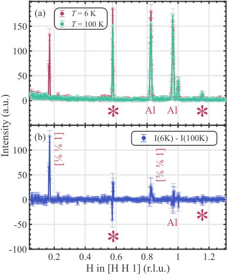
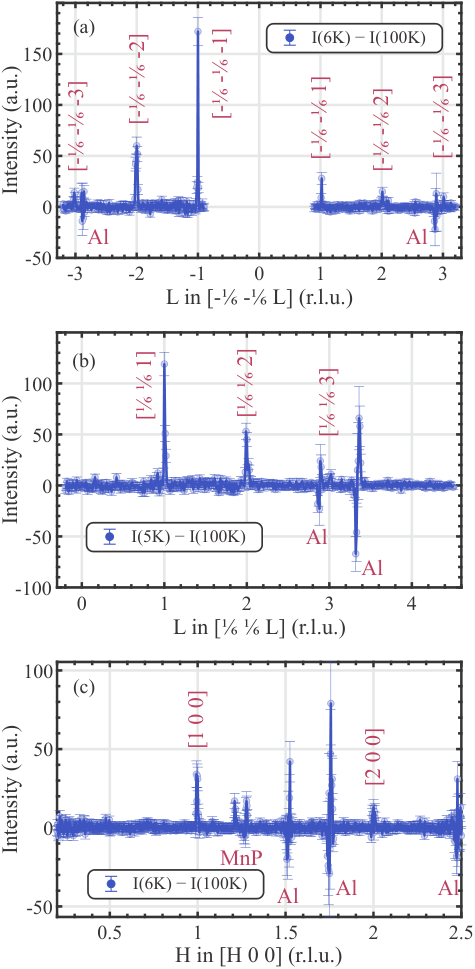
Diffraction scans along the direction at and 100 K in Fig. 2(a) show the emergence of a prominent peak at r.l.u. (reciprocal lattice units) at low temperatures. As shown in Fig. 2(b), the difference between these scans at 6 and 100 K displays magnetic Bragg peaks at and , where . Figure 3(a) shows the difference between scans at 6 and 100 K along , indicating magnetic Bragg peaks at = and . Figure 3(b) shows similar observations of magnetic Bragg peaks at = 1, 2, and 3 in the direction of . Scans along do not show any newly-emerging peaks at low temperatures (not shown). Figure 3(c) shows the difference of scans along at 6 and 100 K with a weak peak at the nuclear reflection and possibly another very weak one at SM-. The other signals that have a negative intensity originate from the Al sample holder. Also, magnetic peaks from a small amount of MnP in the crystal are present in the scan, as indicated. The temperature dependence of does not exhibit a transition at . This implies that that splitting is not significantly related to the observed magnetic structure.
The temperature dependence of the integrated intensity of the (,,1) reflections in Fig. 4 shows a very sharp transition at K that coincides with a previous report indicating a strong first-order magnetic phase transition at this temperature Sangeetha et al. 2021. The fact that the peak intensities of the reflections fall off for larger , as expected from the magnetic form factor of Mn2+, is further evidence that these newly observed Bragg peaks are magnetic in origin. Below, we propose various related magnetic structures that are consistent with the experimental observations assuming the magnetic propagation vector is = r.l.u. with .

III.2 Analysis of experimental results
The observed propagation vector indicates that the magnetic structure consists of a nuclear basal unit cell. Figure 5(a) is a compilation of the magnetic reflections observed in the plane, where the sizes of the circles (i.e., peaks) approximate the observed intensities. A systematic analysis reveals that there are seven magnetic space groups (MSGs) that are consistent with the observed magnetic-diffraction patterns. These are , , , , , , and (See Fig. 6). The first two have higher symmetry and , are descendants of , while , , and are descendants of , and the group has the lowest symmetry (see Fig. 3 and the Supplemental Material (SM) SM- for details).
We now describe an intuitive approach to the magnetic model structure (corresponding to ), which is constructed by creating a in-plane nuclear unit cell that spans the corrugated honeycomb structure, i.e., the bilayer magnetic structure stacked along the -axis [Fig. 5(b)]. Throughout, the red sites correspond to one trigonal magnetic sublattice and the green sites to the other magnetic sublattice. A magnetic model is constructed by assigning a moment along a high symmetry direction at an origin, for instance, at the lower-left corner, and then successively rotating the spin on the nearest neighbors on the same sublattice clockwise by 60∘. The other sublattice is constructed similarly and stacked with anti-parallel spins with respect to the first sublattice. See more details on the construction of the magnetic structure in the SM SM-. Note that along the and directions, the magnetic structure of each sublattice is a cycloid with a 60∘ turn angle. Thus, for each sublattice, the overall structure is a cycloid with propagation vector , with . Inspection of Figure 5b shows that each hexagon consists of two NN antiparallel pairs and one antiparallel NNN pair, such that the net magnetic moment in each hexagon is zero. Also, note that in this model all NN spins along the long diagonal are antiparallel.

To model the intensities of the magnetic peaks, , we use the following equation:
| (1) |
where is a scale factor, is the scattering vector, and are the position of Mn moment and the unit vector of the magnetic moment, respectively. is the magnetic form factor of Mn2+. Using Eq. (1), the calculated magnetic intensities shown in Fig. 5(c) are in good agreement with the experimental results shown in Fig. 5(a).
The intensity calculations [Eq. (1)] allow us to estimate the average ordered magnetic moment, , where is the spectroscopic-splitting factor, is the spin quantum number, and is the Bohr magneton. By comparing nuclear-peak intensities and their structure factors to the observed magnetic-peak intensities, we estimate , typical for Mn2+ moments.
IV Theoretical discussion

IV.1 Modeling in terms of a Heisenberg Hamiltonian
We interpret the experimental results in the framework of a two-dimensional -- Heisenberg model including local anisotropy terms on the honeycomb lattice. We find that this model adequately describes the moments on the puckered-honeycomb Mn2+ ions in a single layer of CaMn2P2. Since moments in different layers order ferromagnetically in the three-dimensional crystal, we focus on a single layer in the following. Our model includes NN interactions , NNN , and third neighbor interactions . We also include single-ion anisotropies and that force the moments to lie within the lattice plane () and introduce a sixfold in-plane anisotropy (), in agreement with the crystalline (point group or ) and time-reversal symmetries. Since the orbital moment of Mn2+ vanishes according to Hund’s rules, the sixfold anisotropy in CaMn2P2 is expected to be small. We model the spins classically, which is well justified given our experimental observation that . The Hamiltonian reads
| (2) |
where are vectors normalized to , and denote lattice sites of the honeycomb lattice. The summation over runs over each -th-neighbor bond once. The honeycomb lattice is generated by the triangular Bravais lattice vectors with , and . Here, we set the Bravais lattice constant . The basis sites are and such that the composite index in Eq. (2) reads with . The reciprocal-lattice vectors are given by and , and the first Brillouin zone is depicted in Fig. 7(a). To connect to our experimental notation, we write a vector in momentum space as such that the -point is located at (corners of the BZ) and one of the -points is located at (at the center of the BZ edges).
Next, we analyze the classical ground states of Eq. (2) assuming coplanar magnetic order. The ground state phase diagram of the -- Heisenberg model was derived in Refs. Rastelli et al. 1979; Katsura et al. 1986; Fouet et al. 2001. A coplanar ground state is in agreement with our experimental data and findings in the literature for the -- model Rastelli et al. 1979; Katsura et al. 1986; Fouet et al. 2001. It can always be favored by a sufficiently-large single-ion anisotropy . In the following we assume , corresponding to easy-plane anisotropy, forcing the spins to lie in the plane. Following Ref. Mulder et al. 2010, we parameterize the coplanar spin configuration on the two sublattices as
| (3a) | ||||
| (3b) | ||||
Here, describes the phase difference between the spins on the and sublattices in the same unit cell . Note that Eq. (3b) contains an explicit minus sign such that corresponds to an antiferromagnetic arrangement of and spins in the same unit cell. Using this spin parametrization, the classical energy per spin ( = number of spins) reads
| (4) |
Here, and such that . We can analytically find the classical ground state energy from the conditions
| (5) |
Let us first discuss the case of . Then, the ground state exhibits a continuous degeneracy of spiral states with wavevectors that fulfill Mulder et al. 2010
| (6) |
The phase difference is determined by
| (7) |
For , the manifold of degenerate wavevectors forms a circle around the point, as shown in Fig. 7(a) for . The radius of the circle increases continuously with increasing . For , the degenerate states are located around the and points, which they approach in the large limit Mulder et al. 2010. We refer to the SM for a detailed derivation of these results. In CaMn2P2 we find the propagation vector , which lies along the - direction and corresponds to one of the degenerate states for . This regime of large frustration is thus relevant for CaMn2P2 and will be our focus in the following.
Nonzero selects a discrete subset of six wavevectors for the ground state spin configuration. For AFM these lie along the - (and symmetry related) directions in the Brillouin zone [see red hexagons in Fig. 7(a)]. In contrast, for FM these lie along the - direction for [see blue dots in Fig. 7(a)] and along the - line for (not shown). The wavevectors shown in Fig. 7(a) are for AFM (red hexagons) and for FM (blue circles). Since AFM favors Néel order, which is described by and , the red wavevectors move towards the point with increasing AFM . In contrast, with increasing FM (i.e. more negative values), they move towards the point. We note that quantum and thermal fluctuations also select six discrete wavevectors, which correspond to the ones favored by FM Mulder et al. 2010. We therefore conclude that the experimentally-observed wavevector is consistent with AFM . In contrast, it is not favored by FM and it is also not selected via an order-by-disorder mechanism.
We now analyze the effect of a local sixfold single-ion anisotropy term whose strength is parametrized by [see Eq. (2)]. As shown in Fig. 7(b), nonzero favors a discrete number of spiral states, which are consistent with an alignment of spins along one of the six high symmetry directions on every site. Moving along the direction in the Brillouin zone, we find that equally favors Néel order (, the experimentally observed spiral order with and a shorter spiral with wavevector (-point). These three wavevectors are also highlighted in Fig. 7(a) as purple squares. In addition to these three wavevectors, also favors symmetry-related wavevectors as shown in the lower panel of Fig. 7(b), which are obtained by rotations. In Fig. 7(c), we show that a magnetic spiral with the experimentally-observed wavevector is stabilized over a wide region of and . Specifically, for and , the system will enter a magnetic spiral with at a critical value of (yellow region). The critical value is a convex function of and exhibits a minimum of zero at . For smaller values of , the sixfold anisotropy will drive the system into a Néel-ordered phase instead (gray region), while for larger values of , it will transition into a magnetic spiral with (red region). For nonzero AFM the Néel phase extends until larger values of , which sets a limit to the size of in CaMn2P2.
To study the dependence on more systematically, we plot in Fig. 7(d) the evolution of as a function of AFM for several fixed values of . We focus on the region of , where the Néel-ordered phase competes with the phase. First, we find that the behavior of (solid lines) depends on the value of . Since increasing moves the minimum-energy spiral wavevector towards the point, reduces for , but increases it for . Second, since favors the Néel ordered state over the spiral, we observe that increasing generally reduces the critical value needed to stabilize the Néel phase (dashed lines). The dashed lines are thus monotonously decreasing as a function of . For a given value of , we thus find that for sufficiently large such that the sixfold anisotropy drives the system into the Néel phase. The position of the crossing point between solid and dashed lines in Fig. 7(d) increases with increasing , which is a result of the minimum-energy wavevector lying closer to than to the origin [see Fig. 7(a)].
We conclude from this analysis that when , the presence of a sixfold anisotropy is sufficient to stabilize the spiral order even without a third-neighbor interaction term . The required value of to drive the system from an incommensurate spiral into the commensurate spiral phase vanishes at and remains small in the vicinity of this point. Regarding the effect of nonzero , we find that AFM selects a wavevector along the observed direction while FM selects different wavevectors that are at -rotated directions in the Brillouin zone. An AFM third-neighbor interaction is thus more consistent with our experimental findings than a FM one. Since AFM also favors the Néel state, the minimum-energy spiral wavevector moves towards the origin with increasing . For large , where the wavevector lies between the and the point, this moves closer to and thus reduces the value of necessary to enter the commensurate spiral phase [see blue line in Fig. 7(d)]. For smaller values of , a larger value of drives the system into the Néel phase and can thus be excluded for CaMn2P2. To summarize, the most likely parameter range describing CaMn2P2 is , and .

IV.2 Emergent Potts-nematic order and first-order phase transition
The frustration-induced spiral magnetic order that we observe in CaMn2P2 leads to the emergence of a Potts-nematic order parameter. This composite order parameter is bilinear in the spins and involves their scalar product on nearest-neighbor sites:
| (8) |
This complex bond order parameter is finite and translationally invariant in any of the three spiral magnetic states with . In Fig. 8, we show the three degenerate ground states of the --- Heisenberg model in the regime where and [see Fig. 7(c)]. When placed on the Mn ions in CaMn2P2, this magnetic structure corresponds to magnetic space group (MSG) , which is one of the MSGs that are consistent with experiment (see Fig. 6). The related magnetic structure for , for which the spin at the origin (yellow circle) is rotated by , lies in the MSG that is also consistent with the experimental data. The three panels in Fig. 8 depict the symmetry-related states with propagation vectors and the insets show the value of the spatially homogeneous complex Potts-nematic order parameter, whose argument follows the direction of the ordering wavevector. It is a generalization of the Ising nematic bond order parameter known to underlie the tetragonal to orthorhombic transition via magneto-elastic couplings that is observed in tetragonal iron-based arsenides such as CaFe2As2 Ni et al. 2008; Fernandes et al. 2012.
Under a threefold rotation around an site, the Potts-nematic order parameter transforms as . Under a mirror operation that sends , it transforms as . Its finite temperature behavior is thus described by the Landau-Ginzburg free energy functional of a three-state Potts model Mulder et al. 2010. In three dimensions this analysis predicts a first-order phase transition into a state with long-range Potts order due to a symmetry-allowed third-order term. This is also in agreement with Monte-Carlo simulations Janke and Villanova 1997. The emergence of long-range Potts-nematic order can therefore naturally account for the experimentally-observed first-order magnetic phase transition in CaMn2P2. Note that different honeycomb layers are ordered ferromagnetically along the direction in CaMn2P2, corresponding to an ordering wavevector with integer , where . Since is a composite magnetic order parameter, it is strongly intertwined with magnetism, and the discontinuous development of long-range Potts order at the first-order transition can thus uplift the magnetic transition to occur as a joint first-order transition. The system then simultaneously develops long-range Potts-nematic and magnetic order. Such a behavior is known to occur, for example, in the triangular lattice antiferromagnet Fe1/3NbSe2 Little et al. 2020. This can also explain why the related compounds CaMn2 with = Sb, Bi that exhibit Néel order, for which such a 3-state Potts-nematic order is absent, develop magnetic order via a continuous phase transition.
Since long-range Potts-nematic order breaks the threefold rotation symmetry of the lattice, we predict the emergence of three lattice distortion domains due to a finite magneto-elastic coupling. The domains are characterized by different values of the Potts-nematic order parameter , as shown in Fig. 8. However, the coupling between magnetic and lattice degrees of freedom is expected to be small in this system, since the orbital moment of the magnetic ions Mn2+ vanishes according to the Hund’s rules and spin-orbit coupling is therefore small. This could be the reason why lattice distortion and crystal symmetry lowering could not be detected in previous x-ray diffraction studies Sangeetha et al. 2021. An alternative explanation is the emergence of a complex multi- magnetic order that preserves all lattice symmetries. It is worth noting, however, that Raman scattering studies have reported the appearance of additional peaks when going from the paramagnetic phase at room temperature to the magnetic phase at Li, Y. J. et al. 2020. Further investigations of the effects of magnetic ordering on the lattice and its excitations are needed to address these open questions. We emphasize that magnetic spiral- order with a single finite-momentum wavevector breaks threefold rotation symmetry via selection of one of the three symmetry-equivalent propagation vectors . In the single- spiral state we thus expect the appearance of three magnetic domains characterized by different magnetic propagation vectors in the magnetically ordered state.
V Conclusions
Using neutron-diffraction measurements, we find that CaMn2P2 undergoes a first-order antiferromagnetic transition at K into a state with a times enlarged magnetic unit cell. The average ordered magnetic moment is . The integrated intensity of the major magnetic peak versus temperature shows an abrupt decrease in intensity at that is a characteristic of a first-order phase transition. Focusing on the experimentally discovered ground-state, we interpret these results using a frustrated -- Heisenberg model with easy-plane anisotropy and a sixfold in-plane anisotropy , and show that this propagation wavevector signals the presence of a substantial degree of frustration. We relate the appearance of the first-order magnetic transition to a composite three-state Potts-nematic bond order parameter that simultaneously develops long-range order and drives the magnetic transition to become first-order. Based on our analysis we predict the emergence of three symmetry related magnetic and lattice distortion domains that deserve further studies.
Acknowledgements.
This research was supported by the U.S. Department of Energy, Office of Basic Energy Sciences, Division of Materials Sciences and Engineering. Ames Laboratory is operated for the U.S. Department of Energy by Iowa State University under Contract No. DE-AC02-07CH11358.References
- Chaloupka et al. (2010) J. Chaloupka, G. Jackeli, and G. Khaliullin, Kitaev-Heisenberg Model on a Honeycomb Lattice: Possible Exotic Phases in Iridium Oxides A2IrO3, Phys. Rev. Lett. 105, 027204 (2010).
- Trebst and Hickey (2022) S. Trebst and C. Hickey, Kitaev materials, Physics Reports 950, 1 (2022).
- Morey et al. (2019) J. R. Morey, A. Scheie, J. P. Sheckelton, C. M. Brown, and T. M. McQueen, Ni2Mo3O8 : Complex antiferromagnetic order on a honeycomb lattice, Phys. Rev. Materials 3, 014410 (2019).
- Yehia et al. (2010) M. Yehia, E. Vavilova, A. Möller, T. Taetz, U. Löw, R. Klingeler, V. Kataev, and B. Büchner, Finite-size effects and magnetic order in the spin- 1 2 honeycomb-lattice compound InCu2/3V1/3O3, Phys. Rev. B 81, 060414 (2010).
- Iakovleva et al. (2019) M. Iakovleva, O. Janson, H.-J. Grafe, A. P. Dioguardi, H. Maeter, N. Yeche, H.-H. Klauss, G. Pascua, H. Luetkens, A. Möller, B. Büchner, V. Kataev, and E. Vavilova, Ground state and low-temperature magnetism of the quasi-two-dimensional honeycomb compound InCu2/3V1/3O3, Phys. Rev. B 100, 144442 (2019).
- Smirnova et al. (2009) O. Smirnova, M. Azuma, N. Kumada, Y. Kusano, M. Matsuda, Y. Shimakawa, T. Takei, Y. Yonesaki, and N. Kinomura, Synthesis, Crystal Structure, and Magnetic Properties of Bi3Mn4O12(NO3) Oxynitrate Comprising S = 3/2 Honeycomb Lattice, J. Am. Chem. Soc. 131, 8313 (2009).
- Miyamoto et al. (2019) S. Miyamoto, Y. Iwasaki, N. Uemoto, Y. Hosokoshi, H. Fujiwara, S. Shimono, and H. Yamaguchi, Magnetic properties of honeycomb-based spin models in verdazyl-based salts, Phys. Rev. Materials 3, 064410 (2019).
- Kitaev (2006) A. Kitaev, Anyons in an exactly solved model and beyond, Ann. Phys. 321, 2 (2006).
- Baskaran et al. (2008) G. Baskaran, D. Sen, and R. Shankar, Spin-S Kitaev model: Classical ground states, order from disorder, and exact correlation functions, Phys. Rev. B 78, 115116 (2008).
- Reuther et al. (2011a) J. Reuther, R. Thomale, and S. Trebst, Finite-temperature phase diagram of the Heisenberg-Kitaev model, Phys. Rev. B 84, 100406 (2011a).
- Price and Perkins (2013) C. Price and N. B. Perkins, Finite-temperature phase diagram of the classical Kitaev-Heisenberg model, Phys. Rev. B 88, 024410 (2013).
- Rastelli et al. (1979) E. Rastelli, A. Tassi, and L. Reatto, Non-simple magnetic order for simple Hamiltonians, Physica B+C 97, 1 (1979).
- Katsura et al. (1986) S. Katsura, T. Ide, and T. Morita, The ground states of the classical heisenberg and planar models on the triangular and plane hexagonal lattices, J Stat Phys 42, 381 (1986).
- Fouet et al. (2001) J. Fouet, P. Sindzingre, and C. Lhuillier, An investigation of the quantum J1-J2-J3 model on the honeycomb lattice, Eur. Phys. J. B 20, 241 (2001).
- Mulder et al. (2010) A. Mulder, R. Ganesh, L. Capriotti, and A. Paramekanti, Spiral order by disorder and lattice nematic order in a frustrated Heisenberg antiferromagnet on the honeycomb lattice, Phys. Rev. B 81, 214419 (2010).
- Albuquerque et al. (2011) A. F. Albuquerque, D. Schwandt, B. Hetényi, S. Capponi, M. Mambrini, and A. M. Läuchli, Phase diagram of a frustrated quantum antiferromagnet on the honeycomb lattice: Magnetic order versus valence-bond crystal formation, Phys. Rev. B 84, 024406 (2011).
- Reuther et al. (2011b) J. Reuther, D. A. Abanin, and R. Thomale, Magnetic order and paramagnetic phases in the quantum J1-J2-J3 honeycomb model, Phys. Rev. B 84, 014417 (2011b).
- Oitmaa and Singh (2011) J. Oitmaa and R. R. P. Singh, Phase diagram of the J1-J2-J3 Heisenberg model on the honeycomb lattice: A series expansion study, Phys. Rev. B 84, 094424 (2011).
- Clark et al. (2011) B. K. Clark, D. A. Abanin, and S. L. Sondhi, Nature of the Spin Liquid State of the Hubbard Model on a Honeycomb Lattice, Phys. Rev. Lett. 107, 087204 (2011).
- Bishop et al. (2012) R. F. Bishop, P. H. Y. Li, D. J. J. Farnell, and C. E. Campbell, The frustrated Heisenberg antiferromagnet on the honeycomb lattice: J1-J2 model, J. Phys.: Condens. Matter 24, 236002 (2012).
- Bishop et al. (2013) R. F. Bishop, P. H. Y. Li, and C. E. Campbell, Valence-bond crystalline order in the s = 1/2 J1-J2 model on the honeycomb lattice, J. Phys.: Condens. Matter 25, 306002 (2013).
- Bishop et al. (2015) R. F. Bishop, P. H. Y. Li, O. Götze, J. Richter, and C. E. Campbell, Frustrated Heisenberg antiferromagnet on the honeycomb lattice: Spin gap and low-energy parameters, Phys. Rev. B 92, 224434 (2015).
- Sahoo and Flint (2020) J. Sahoo and R. Flint, Symmetric spin liquids on the stuffed honeycomb lattice, Phys. Rev. B 101, 115103 (2020).
- Dong and Sheng (2020) X.-Y. Dong and D. N. Sheng, Spin-1 Kitaev-Heisenberg model on a honeycomb lattice, Phys. Rev. B 102, 121102 (2020).
- Jin et al. (2022) H.-K. Jin, W. M. H. Natori, F. Pollmann, and J. Knolle, Unveiling the S=3/2 Kitaev honeycomb spin liquids, Nat Commun 13, 3813 (2022).
- Sangeetha et al. (2021) N. S. Sangeetha, S. Pakhira, Q.-P. Ding, L. Krause, H.-C. Lee, V. Smetana, A.-V. Mudring, B. B. Iversen, Y. Furukawa, and D. C. Johnston, First-order antiferromagnetic transitions of SrMn2P2 and CaMn2P2 single crystals containing corrugated-honeycomb Mn sublattices, Proc. Natl. Acad. Sci. 118, 10.1073/pnas.2108724118 (2021).
- Sangeetha et al. (2016) N. S. Sangeetha, A. Pandey, Z. A. Benson, and D. C. Johnston, Strong magnetic correlations to 900 K in single crystals of the trigonal antiferromagnetic insulators SrMn2As2 and CaMn2As2, Phys. Rev. B 94, 094417 (2016).
- Simonson et al. (2012) J. W. Simonson, G. J. Smith, K. Post, M. Pezzoli, J. J. Kistner-Morris, D. E. McNally, J. E. Hassinger, C. S. Nelson, G. Kotliar, D. N. Basov, and M. C. Aronson, Magnetic and structural phase diagram of CaMn2Sb2, Phys. Rev. B 86, 184430 (2012).
- Sangeetha et al. (2018) N. S. Sangeetha, V. Smetana, A.-V. Mudring, and D. C. Johnston, Antiferromagnetism in semiconducting SrMn2Sb2 and BaMn2Sb2 single crystals, Phys. Rev. B 97, 014402 (2018).
- Das et al. (2017) P. Das, N. S. Sangeetha, A. Pandey, Z. A. Benson, T. W. Heitmann, D. C. Johnston, A. I. Goldman, and A. Kreyssig, Collinear antiferromagnetism in trigonal SrMn2As2 revealed by single-crystal neutron diffraction, J. Phys.: Condens. Matter 29, 035802 (2017).
- Bridges et al. (2009) C. Bridges, V. Krishnamurthy, S. Poulton, M. Paranthaman, B. Sales, C. Myers, and S. Bobev, Magnetic order in CaMn2Sb2 studied via powder neutron diffraction, Journal of Magnetism and Magnetic Materials 321, 3653 (2009).
- Gibson et al. (2015) Q. D. Gibson, H. Wu, T. Liang, M. N. Ali, N. P. Ong, Q. Huang, and R. J. Cava, Magnetic and electronic properties of CaMn2Bi2: A possible hybridization gap semiconductor, Phys. Rev. B 91, 085128 (2015).
- Ratcliff II et al. (2009) W. Ratcliff II, A. Lima Sharma, A. Gomes, J. Gonzalez, Q. Huang, and J. Singleton, The magnetic ground state of CaMn2Sb2, J. Magn. Magn. Mater. 321, 2612 (2009).
- Islam et al. (2020) F. Islam, E. Gordon, P. Das, Y. Liu, L. Ke, D. L. Abernathy, R. J. McQueeney, and D. Vaknin, Spin dynamics in antiferromagnetic oxypnictides and fluoropnictides: LaMnAsO, LaMnSbO, and BaMnAsF, Phys. Rev. B 101, 155119 (2020).
- Brock et al. (1994) S. L. Brock, J. Greedan, and S. M. Kauzlarich, Resistivity and magnetism of AMn2P2 (A = Sr, Ba): The effect of structure type on physical properties, J. Solid State Chem. 113, 303 (1994).
- Little et al. (2020) A. Little, C. Lee, C. John, S. Doyle, E. Maniv, N. L. Nair, W. Chen, D. Rees, J. W. F. Venderbos, R. M. Fernandes, J. G. Analytis, and J. Orenstein, Three-state nematicity in the triangular lattice antiferromagnet Fe1/3NbS2, Nat. Mater. 19, 1062 (2020).
- Fernandes et al. (2019) R. M. Fernandes, P. P. Orth, and J. Schmalian, Intertwined Vestigial Order in Quantum Materials: Nematicity and Beyond, Annu. Rev. Condens. Matter Phys. 10, 133 (2019).
- McNally et al. (2015) D. E. McNally, J. W. Simonson, J. J. Kistner-Morris, G. J. Smith, J. E. Hassinger, L. DeBeer-Schmitt, A. I. Kolesnikov, I. A. Zaliznyak, and M. C. Aronson, CaMn2Sb2: Spin waves on a frustrated antiferromagnetic honeycomb lattice, Phys. Rev. B 91, 180407 (2015).
- (39) See Supplemental Material at http://link.aps.org/supplemental/ for details on constructing the magnetic structure and systematically searching other magnetic structures., .
- Perez-Mato et al. (2015) J. Perez-Mato, S. Gallego, E. Tasci, L. Elcoro, G. de la Flor, and M. Aroyo, Symmetry-based computational tools for magnetic crystallography, Annu. Rev. Mater. Res. 45, 217 (2015).
- Ni et al. (2008) N. Ni, S. Nandi, A. Kreyssig, A. I. Goldman, E. D. Mun, S. L. Bud’ko, and P. C. Canfield, First-order structural phase transition in CaFe2As2, Phys. Rev. B 78, 014523 (2008).
- Fernandes et al. (2012) R. M. Fernandes, A. V. Chubukov, J. Knolle, I. Eremin, and J. Schmalian, Preemptive nematic order, pseudogap, and orbital order in the iron pnictides, Phys. Rev. B 85, 024534 (2012).
- Janke and Villanova (1997) W. Janke and R. Villanova, Three-dimensional 3-state Potts model revisited with new techniques, Nuclear Physics B 489, 679 (1997).
- Li, Y. J. et al. (2020) Li, Y. J., Jin, F., Mi, Z. Y., Guo, J., Wu, W., Yu, Z. H., Wu, D. S., Na, S. H., Mu, C., Zhou, X. B., Li, Z., Liu, K., Sun, L. L., Zhang, Q. M., Xiang, T., Li, G., and Luo, J. L., First-order transition in trigonal structure CaMn2P2, EPL 132, 46001 (2020).
Supplemental Material
Frustrated Magnetic Cycloidal Structure and Emergent Potts Nematicity in CaMn2P2
Farhan Islam1,2, Thaís V. Trevisan1,2, Thomas Heitmann3, Santanu Pakhira1, Simon X. M. Riberolles1, N. S. Sangeetha1, David C. Johnston1,2, Peter P. Orth1,2, David Vaknin1,2
1 Ames National Laboratory, Iowa State University, Ames, Iowa 50011, USA
2Department of Physics and Astronomy, Iowa State University, Ames, Iowa 50011, USA
3The Missouri Research Reactor and Department of Physics and Astronomy, University of Missouri, Columbia, Missouri 65211, USA
I Constructing the Magnetic Structure
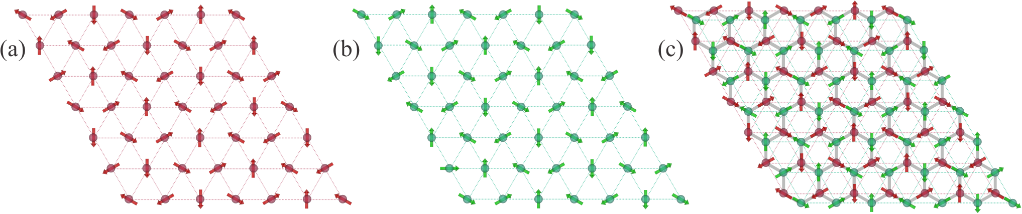
We describe the proposed magnetic structures with space group , shown in Fig. 5(b) in the main text. The magnetic structure is constructed by generating two in-plane trigonal sublattices that are stacked together to form the honeycomb structure. In Fig. S1(a), the trigonal sublattice is constructed by assigning a spin at the origin (lower-left corner) pointed along one of the high-symmetry directions, and successively rotating the nearest neighbors in the - and - directions by a 60∘ angle in the counter-clockwise direction. In Fig. S1(b) we construct the other trigonal sublattice for magnetic structure. The spin at the origin (lower-left corner) is flipped with respect to the spin at the origin of the trigonal sublattice depicted in Fig. S1(a). The nearest neighbors along the and directions are rotated successively by a 60∘ angle in the counter-clockwise direction, the same way as before, to construct the other sublattice. The magnetic structure with spacegroup is formed by stacking the trigonal sublattice shown in Fig. S1(b) on the trigonal sublattice shown in Fig. S1(a) to form the corrugated honecycomb lattice, as depicted in Fig. S1(c).
II Systematically Searching Other Magnetic Structures
We emphasize that the magnetic structure shown in Fig. 5(b) of the main text with magnetic space group Perez-Mato et al. 2015 is not unique with respect to the neutron-diffraction data. Systematically searching through the Symmetry-Based Computational Tools for Magnetic Crystallography Perez-Mato et al. 2015 (Fig. 6 in the main text), we find a few more magnetic structures shown in Fig. S2 that are consistent with the peak positions in the diffraction measurements. The Bilbao crystallographic database allows for other magnetic structures with the propagation vector of (1/6, 1/6, 0), as shown in Fig. S3; however, the intensity calculations are inconsistent with the experimental observations. In particular, these configurations show intensities at (1/6, 1/6, 0), which are not observed experimentally. We note that when constructing the magnetic structure using the Bilbao database, we assume that the spin direction at the origin is a high-symmetry direction, and rotate nearest-neighbor moments in the same sublattice by . For simplicity, we divide the rotation between the spin at the origin and the edge by six, i.e. .

