Self-heating of cryogenic high-electron-mobility transistor amplifiers and the limits of microwave noise performance
Abstract
The fundamental limits of the microwave noise performance of high electron mobility transistors (HEMTs) are of scientific and practical interest for applications in radio astronomy and quantum computing. Self-heating at cryogenic temperatures has been reported to be a limiting mechanism for the noise, but cryogenic cooling strategies to mitigate it, for instance using liquid cryogens, have not been evaluated. Here, we report microwave noise measurements of a packaged two-stage amplifier with GaAs metamorphic HEMTs immersed in normal and superfluid 4He baths and in vacuum from 1.6 – 80 K. We find that these liquid cryogens are unable to mitigate the thermal noise associated with self-heating. Considering this finding, we examine the implications for the lower bounds of cryogenic noise performance in HEMTs. Our analysis supports the general design principle for cryogenic HEMTs of maximizing gain at the lowest possible power.
I Introduction
Microwave low-noise amplifiers (LNAs) based on III-V semiconductor high electron mobility transistor (HEMT) technology pospieszalski_extremely_2005; bautista_chapter_2008 are a key component of high precision measurements across diverse fields in science and engineering such as radio astronomy pospieszalski_extremely_2018; chiong_low-noise_2022, deep-space communication bautista_cryogenic_2001, and quantum computing chow_implementing_2014; hornibrook_cryogenic_2015; krantz_quantum_2019; cha_300-w_2020; bardin_microwaves_2021. In these applications, LNAs serve as the first or second stage of amplification in the receiver chain, thereby making a decisive contribution to the noise floor of the entire measurement apparatus. Although marked improvements in noise performance have been achieved in recent decades bautista_cryogenic_2001; wadefalk_cryogenic_2003; schleeh_ultralow-power_2012; akgiray_noise_2013; varonen_75116-ghz_2013; cuadrado-calle_broadband_2017; cha_0314_2018; heinz_noise_2020, the noise performance of HEMT LNAs remains a factor of 3 – 5 larger than the quantum limit chiong_low-noise_2022; cha_inp_2020; schleeh_cryogenic_2013.
The noise behavior of HEMT amplifiers is typically interpreted using the Pospieszalski model pospieszalski_modeling_1989. In this model, noise generators are assigned to the gate resistance at the input and the drain conductance at the output, parameterized by noise temperatures and , respectively. The drain temperature lacks an accepted physical origin, with several theories having been proposed statz_noise_1974; pospieszalski_limits_2017; gonzalez_noise_1997; esho_theory_2022, and it is typically taken as a fitting parameter. The gate temperature is assumed to be equal to the physical device temperature pospieszalski_extremely_2005; bautista_physical_2007. In this interpretation, cryogenic cooling leads to improvements in the noise figure of the HEMT in part by decreasing the gate temperature and hence its thermal noise.
The monotonic decrease in noise figure with decreasing physical temperature has been observed to plateau below physical temperatures of 20 – 40 K (see Fig. 10 from Ref. duh_32-ghz_1989, Fig. 1 from Ref. schleeh_phonon_2015 and Fig. 2 from Ref. mcculloch_dependence_2017, for example). Recent numerical and experimental studies have attributed this plateau to heating of the gate caused by power dissipated in the active channel, referred to as self-heating schleeh_phonon_2015; choi_characterization_2021. In more detail, optimal low-noise performance at cryogenic temperatures requires power dissipation on the order of milliwatts. At these temperatures, the observed thermal resistance from Schottky thermometry is consistent with that expected of phonon radiation for which the thermal resistance varies as choi_alexander_youngsoo_investigation_2022. Consequently, at physical temperatures K the rapid increase in thermal resistance with decreasing temperature leads to a plateau in the gate temperature, which produces a corresponding plateau in noise figure.
Mitigating the effect of self-heating by enhancing heat dissipation is desirable. However, cryogenic thermal management of the gate in modern devices with sub-micron gate lengths and a buried gate structure is challenging. Existing on-chip cooling methods muhonen_micrometre-scale_2012 must be evaluated for their capability to provide cooling while avoiding detrimental impact on device noise performance. An alternate approach that does not require any device modifications is to submerge the heated surface in superfluid 4He, a quantum fluid with the highest known thermal conductivity van_sciver_helium_2012. Such an approach is routinely used for cryogenic thermal management of superconducting magnets beig_applications_2001 and is actively employed in high-energy physics experiments kittel_cooling_1998; baudouy_heat_2014; weisend_ii_twenty-three_2016. However, the effectiveness of liquid cryogens to mitigate self-heating in HEMTs has not been experimentally evaluated.
Here, we present noise measurements of a packaged two-stage amplifier with GaAs metamorphic HEMTs immersed in normal (He I) and superfluid (He II) 4He baths as well as in vapor and vacuum environments up to 80 K at various biases. We find that the liquid cryogens are unable to mitigate self-heating owing to the thermal boundary resistance between the HEMT surface and the 4He bath. We extract the gate temperature using a small-signal model of the device and show that the trends with physical temperature are generally consistent with those predicted by a phonon radiation model, regardless of the presence of liquid cryogens. We use these observations to examine the lower bounds of noise performance in cryogenic HEMTs, accounting for the temperature and power dissipation dependence of the thermal noise at the input.
II Experiment
II.1 Overview of measurement apparatus
We measured the microwave noise temperature and gain of the device under test (DUT), a common-source two-stage packaged amplifier comprised of OMMIC D007IH GaAs metamorphic HEMTs heinz_noise_2020, each with a 70 nm gate length and a 4 finger 200 m width gate structure consisting of an InGaAs-InAlAs-InGaAs-InAlAs epitaxial stack on a semi-insulating GaAs substrate with each stage biased nominally identically, using the cold attenuator Y-factor method leffel_y_2021. An input matching network (IMN) was employed to match the optimal transistor impedance to the 50 impedance of our measurement system over a 4–5.5 GHz bandwidth (see SI section S.1 and Ch. 5.1 of Ref. akgiray_ahmed_halid_new_2013 for more details).
Figure 1 shows a schematic of the measurement setup designed for microwave noise characterization in a liquid 4He dewar. The DUT, packaged 20 dB chip attenuator, temperature diodes and heater (mounted behind the stage and not shown) were screw-mounted to a copper mounting stage using indium foil. The stage was screw-mounted to a dipstick, and a liquid level sensor was taped to the interior wall of the dipstick. The dipstick was designed to mount on a 60 L dewar neck and submerge the stage in the liquid bath. A custom vacuum fitting with hermetic SubMiniature-A (SMA) and DC feedthroughs was sealed to the dewar neck, allowing for evaporative cooling via pumping. SMA coaxial cables and phosphor-bronze cryogenic wires were used to transmit microwave and DC signals, respectively, between the stage and feedthroughs.
Noise power was generated by a packaged 2 – 18 GHz solid state SMA noise diode with 15 dB excess noise ratio (ENR), which was biased using a MOSFET biasing circuit switched by an Agilent 33220A signal generator. This scheme allowed for Y-factor sampling up to 100 kHz, limited by the RC time constant of the MOSFET and noise diode circuit. Following the cold attenuator method fernandez_noise-temperature_1998, this noise power was directed through 0.141” diameter coaxial cabling to the 20 dB attenuator thermally strapped to the stage. The resulting hot and cold noise temperatures presented to the input plane of the DUT under cryogenic conditions were 52 K and 7 K respectively, yielding a Y-factor of 7.4. The noise power amplified by the DUT was then directed to a room temperature measurement apparatus. The 4He dewar was earthed, and inner-outer DC blocks were used to connect the hermetic feedthroughs to the noise source and backend to minimize low-frequency bias noise on the DUT.

Figure 1 also shows the room temperature backend measurement chain, which consisted of the following components. The microwave power emerging from the SMA feedthrough output first passed through a 3–6 GHz microwave isolator to improve impedance matching and minimize reflections. Two Minicircuits ZX60-83LN-S+ broadband amplifiers were placed sequentially following the isolator. A microwave filter was then used to limit the bandwidth of power amplified by the final gain stage, a Miteq AMF-3B-04000800-25-25P power amplifier. Next, a microwave switch was used to periodically switch between the signal path and a 50 load, enabling re-calibration of the backend to correct for DC offset drifts. A variable attenuator and temperature-controlled YIG filter were then used to set the magnitude and frequency of microwave noise power reaching the Herotek DT4080 tunnel diode, which linearly transduced this power into a DC voltage. Inner-outer DC blocks were placed at the tunnel diode’s input to eliminate unwanted biasing. The final DC signal was amplified and low-pass filtered by an SRS560 pre-amplifier and then digitized by an analog-digital converter for further data processing.
Figure 1 shows representative Y-factor voltage data spanning one duty cycle of data acquisition and backend re-calibration. Here, the hot (noise source on), cold (noise source off) and zero-power offset (50 load) output voltages at time index , denoted , and , respectively, were analog filtered at 1 kHz and over-sampled at kHz to avoid aliasing artifacts. The noise source was pulsed at Hz, and the zero-power offset was re-calibrated at Hz with a 10% duty cycle, yielding a voltage offset integration time of s. Each half-pulse of hot (cold) voltage data was integrated for its duration s. The first and last half-pulses of each cycle were discarded due to the ms switching time of the microwave switch, yielding 8 total pulses. The integrated zero-power offset was subtracted from each integrated hot (cold) half-pulse to give hot (cold) offset-corrected data () for each pulse . This procedure yielded Y-factor data effectively sampled at with 0.2 s of data skipped every 1 s. The expression for the measured Y-factor for pulse considering the above specifications is:
| (1) |
where ranges from 1 to 8 for each cycle, is the number of sampled points in each half-pulse, is the number of sampled points in each calibration pulse, is the time index at the start of the th hot pulse, is the time index at the center of the th pulse when the noise source switches from hot to cold, and is the time index at the end of the th cold pulse. For all steady-state data shown in this paper, the Y-factor was further averaged over a total measurement time s.
A Rhode&Schwarz RSZVA50 VNA calibrated with a Maury 8050CK20 SOLT calibration kit was used for measurements. To measure gain and noise temperature simultaneously through Y-factor measurements, the gain of the entire system from the noise source output plane to the backend input plane was first measured using the VNA, where is the total loss of the cables with input cable loss , output cable loss , and attenuator loss . The DUT gain could then be extracted from the backend voltage under different conditions using:
| (2) |
where , and are hot and cold output calibration voltages and total calibration gain (including cabling and attenuator), respectively, all measured at a particular device bias. The noise temperature was then determined by:
| (3) |
where K, is the noise source excess noise ratio, is the noise source physical temperature, is the lumped coaxial cable physical temperature, is the attenuator physical temperature, and is the backend noise temperature (see SI section S.2 for a derivation of Eqs. 2 and 3).
II.2 Measurement apparatus calibration
We now describe the calibration procedure for each term of Eqs. 2 and 3. First, the backend noise temperature was independently obtained using a liquid nitrogen cooled fixed load method. The noise source ENR was then calibrated by using the backend detector as a reference amplifier (see SI section S.3 for more details). Two separate liquid 4He dewar baths were then used, one to calibrate the coaxial cable loss and temperature and then another to calibrate the attenuator loss.
The general procedure in each calibration dewar was as follows. The dipstick was used to submerge the mounting stage 2 cm from the bottom of a fully filled 60 L liquid 4He dewar at 4.2 K and ambient pressure. After waiting 30 minutes for thermal equilibration, calibration measurements were taken. The dewar was then sealed, and a Leybold DK50 rotary piston vacuum pump was used to evaporatively cool the liquid into the He II phase. An Anest Iwata ISP-500 scroll pump was connected in series and switched on after approximately 2 hours of pumping. A steady-state temperature of 1.6 K was reached (corresponding to a vapor pressure of 5.60 Torr) after roughly 6 hours of pumping, and further calibration measurements were taken as described in the following paragraphs. A heater was then switched on for less than 2 hours to accelerate the boil-off rate of the remaining liquid, and switched off when a spike in stage temperature was observed which indicated that the liquid surface had dropped below the stage. Further calibration was performed after turning off the heater as the stage was allowed to warm from 1.6 K under the ambient heating power of the measurement apparatus (see SI section S.3 for more details). The dewar was then back-filled with 4He exchange gas to facilitate thermalization to room temperature, at which point the dipstick was removed.

We now discuss the details of the measurements in each calibration dewar. In the first calibration dewar, the attenuator and DUT shown in the configuration of Fig. 1 were replaced with a short through which was thermally anchored to the copper stage. Figure 2 shows the total loss of the coaxial cables measured at room temperature in air and in the first calibration dewar at 4.2 K and 1.6 K. To isolate the individual cable losses and , these losses were also measured independently at room temperature, and their ratio was assumed to remain constant for all temperatures.
The lumped coaxial cable physical temperature , which is the effective temperature at which the cables radiate their noise power, was measured directly using the Y-factor method. Figure 2 shows the measured lumped temperature versus frequency with the cables dipped in a 4.2 K He I bath. We assumed that both cables were at the same physical temperature. The 1.6 K He II calibration measurement is omitted for clarity as it is within 10 K of the He I measurement. To support the accuracy of the measured effective coaxial cable temperature, we estimated the value using an extension of the cable temperature model from Ref. soliman_thermal_2016. This estimate is shown in Fig. 2 and is in agreement with the measured values (see SI section S.4 for more details).
In the second calibration dewar, the short through was replaced by the 20 dB attenuator. The total loss was measured using the same procedure as in the first calibration dewar, and the attenuator loss was extracted by dividing by the previously measured . A measurement of the temperature of the attenuator using the Y-factor method was not possible in this case due to the larger loss of the attenuator. Instead, the temperature of the attenuator was measured by a calibrated LakeShore DT-670-SD temperature diode indium-bonded directly to the attenuator chip. The diode calibration curve was provided by LakeShore, and the saturated liquid temperature of He I at 4.23 K was used to correct for DC offsets. We assumed that negligible temperature differences existed between the attenuator, mounting stage, and DUT, and we therefore took the DUT physical temperature to be . All temperature diodes were measured using a LakeShore 336 temperature controller, which converted the temperature to a voltage measured by the DAQ synchronously with all Y-factor measurements.
II.3 LNA noise and gain measurements
With the calibration data obtained, the noise temperature and gain of the DUT was measured using two additional liquid 4He dewar baths at various frequencies, temperatures, and biases. The gate-source and drain-source bias voltages and , which were nominally applied equally to each individual transistor, were varied to yield transistor drain-source current densities from 35 mA mm-1 to 120 mA mm-1, corresponding to dissipated power densities per transistor of 15 mW mm-1 to 150 mW mm-1. The relevant measured values from the calibration procedure described above were used to extract and from Eqs. 2 and 3.
In the first measurement dewar, the device was mounted to the stage in the configuration shown in Fig. 1, and the cooldown procedure followed that of the calibration dewars described above. At each physical temperature, the DUT bias was varied and Y-factor measurements were taken versus frequency by adjusting the YIG filter frequency. In addition, the calibration measurement of , and was performed, with the DUT bias chosen for convenience to be its low-noise bias. Using these measurements, the device gain could be extracted from Y-factor voltage measurements at any bias using Eq. 2 without requiring a separate VNA measurement. This calibration was found to be stable over several days, and it was repeated each day before data acquisition.
In addition to measurements under specific liquid cryogen environments, continuous Y-factor measurements were also taken as the He II bath was pumped away, yielding noise data both before and after the DUT gate was submerged. The measurements were performed at a fixed bias of mA mm-1 and frequency of GHz. The bias was chosen to be sufficiently high that any self-heating mitigation would be readily observed without risking device damage due to prolonged biasing, and the frequency was chosen due to it being the optimum noise match frequency as determined by the IMN akgiray_ahmed_halid_new_2013.
The He II film creep effect allen_properties_1939 was expected to cause the entire mounting stage, including the heated DUT region, to be coated in a superfluid film even after the liquid bath surface dropped below the DUT height. We used the sharp rise observed in the attenuator and stage temperature measurements to indicate the complete evaporation of He II from the stage. The DUT noise was also measured on warming from 1.6 K to 80 K in the vacuum space left after all liquid was pumped away. In the second measurement dewar, the noise temperature was again measured in 4.2 K liquid using the same procedure as in the first measurement dewar but without the subsequent evaporative cooling step. Instead, the liquid bath was allowed to evaporate under the heating power of the dipstick, enabling measurements to be taken in a vapor environment at several temperatures after the liquid level dropped below the mounting stage. The vapor warmed sufficiently slowly ( 1 K/hour) such that all measurements were effectively taken in a steady state vapor environment. The calibrations used for these measurements were the same as for the 4.2 K liquid since the coaxial cable loss and temperature were observed to change negligibly up to 45 K stage temperature.
III Results
III.1 Microwave noise temperature versus frequency
We begin by showing the noise temperature and gain versus frequency at various temperatures, bath conditions and biases. Figure 3 shows and versus with the device biased at its low-noise bias of mA mm-1 and immersed in three different bath conditions ranging from 1.6 K He II to 35.9 K vacuum, with measurements in 4.2 K He I and 8.2 K 4He vapor omitted for clarity since they are within within 0.2 K of the He II data. The noise increases monotonically with increasing physical temperature regardless of bath condition. At 4.5 GHz, the noise temperature increases from 2.6 K to 3.3 K with temperature increasing from 20.1 K to 35.9 K, consistent with the expected scaling predicted by the Pospieszalski model and observed in prior studies (see Fig. 2 from Ref. pospieszalski_very_1994, Fig. 1c from Ref. schleeh_phonon_2015, and Fig. 5 from Ref. pospieszalski_dependence_2017, for example). The gain varies by approximately 4 dB over the measured frequency range, peaking at 4 GHz. The gain variation with physical temperature is less than 0.5 dB at fixed and , and so only the He II gain data is shown for clarity.
Figure 3 shows and versus with the device immersed in 1.6 K He II at three different device biases of mA mm-1, mA mm-1, and mA mm-1. At biases below mA mm-1 the noise temperature varies by less than 1.5 K for all frequencies, whereas the noise temperature increases by 5.3 K from mA mm-1 to mA mm-1. The gain increases monotonically with increasing bias while retaining the same shape versus frequency, but it appears to asymptotically plateau at approximately the highest gain shown here, at a bias of mA mm-1.

To interpret these measurements, a microwave model of the full device including IMN, monolithic microwave integrated circuit (MMIC) components and transistor small-signal model was made using Microwave Office noauthor_awr_nodate. The model used micrograph measured values of the IMN, foundry schematic values for the MMIC, and independently measured small-signal model values from nominally identical discrete transistors from Ref. gabritchidze_experimental_2022. The small-signal model and IMN parameters were manually tuned by less than 20% from these starting values to fit both the gain and noise temperature curves (see SI section S.1 for more details). Representative frequency-dependent results of the model are plotted in Figs. 3 and 3. The modelled and measured gain are in quantitative agreement over the full frequency range, and the model captures the overall trend in noise temperature as a function of temperature and bias.
Using this model, we predict the expected change in device noise temperature in different cryogenic environments. Assuming changes from 20 K, the expected elevated gate temperature due to self-heating, to its lowest possible value of 1.6 K, and with all other small-signal parameters remaining unchanged, the model predicts that should decrease from 2.2 K to 0.6 K at GHz. As seen in both Figs. 3 and 3, the lowest measured noise temperature was K, suggesting a gate temperature closer to 20 K. This initial finding suggests that the liquid cryogens are not altering the self-heating of the gate.
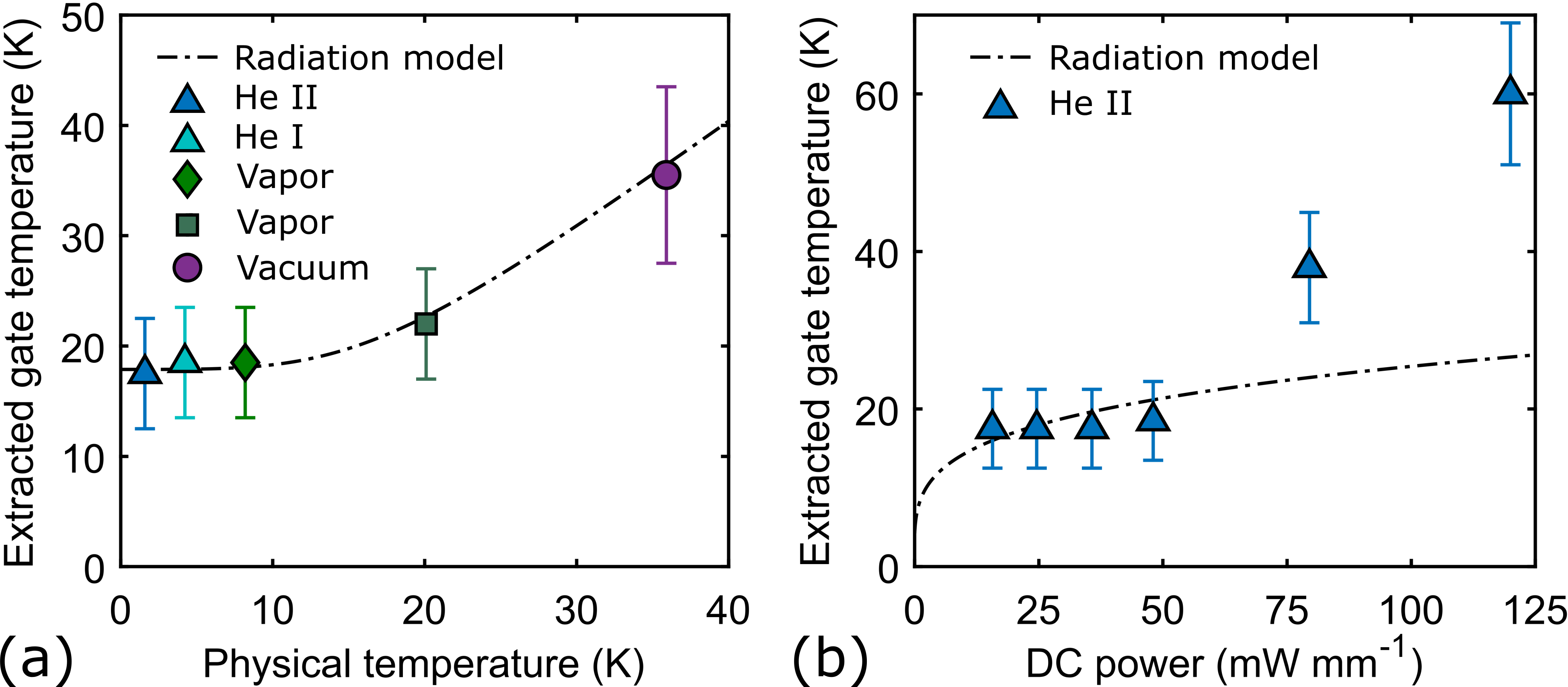
To obtain more quantitative insight, we used the model to extract the gate temperature under various conditions. Figure 4 shows the extracted versus at the device’s low-noise bias of mA mm-1. is elevated above below 20 K even in the presence of superfluid, and equals above 20 K, behavior which is in agreement with prior reports duh_32-ghz_1989; schleeh_phonon_2015; mcculloch_dependence_2017. Figure 4 shows versus at K. Here, changes by less than 2 K for bias powers below mW mm-1, after which increases more rapidly.
We compare the small-signal model results with an equivalent circuit radiation model of the HEMT developed in Ref. choi_characterization_2021. The explicit functional form for the gate temperature derived from this model is:
| (4) |
where is the substrate temperature, W m-2 K-4 is the equivalent Stefan–Boltzmann constant for phonons in GaAs, and is the space resistance between nodes and with emitting line length and view factor which quantifies the fraction of power emitted from surface that intercepts surface . The subscripts , and represent the gate, channel, and substrate, respectively. Following Ref. choi_alexander_youngsoo_investigation_2022, we take nm and compute .
The predictions of Eq. 4 are also shown in Figs. 4 and 4. In Fig. 4 the data and radiation model are in quantitative agreement over the full range of physical temperatures. We note that the model contains no fitting parameters. The extracted gate temperatures in the presence of liquid cryogens agree with the radiation model predictions. The increase in gate temperature with physical temperature above 20 K at fixed bias is also captured. In Fig. 4, the data and model agree at biases below 50 mW mm-1, but the data deviates from the model above mW mm-1. The origin of this discrepancy is presently unclear. A possible explanation is that other noise sources are being attributed to gate thermal noise, leading to artificially high extracted gate temperatures. This additional noise may signal the onset of impact ionization somerville_physical_2000; webster_impact_2000, which is associated with a reduction in gain and an increase in gate leakage current. While the gain was observed to plateau at dB at the highest measured bias, as shown in Fig. 3, a relatively high gate leakage current of 100 A was measured, suggesting some contribution of impact ionization. Excluding this non-ideal behavior at high biases, the good agreement in Fig. 4 supports the phonon radiation mechanism of heat dissipation in cryogenic HEMTs, and it provides further indication that liquid cryogens provide inadequate cooling power to mitigate self-heating in HEMTs.
III.2 Noise temperature dependence on cryogenic environment
We obtain further insight into how liquid cryogens impact HEMT noise performance by examining the DUT noise temperature measured continuously in a changing cryogenic environment. Figure 5 shows the time series of both and measured continuously as the He II was pumped out of the measurement dewar. Here, minutes was chosen as a reference time at which a rise in was observed, interpreted as the departure of superfluid from the attenuator and device. A corresponding feature in the DUT noise temperature is absent, suggesting that the superfluid cooling has no measureable effect on the DUT noise performance. After minutes the device thermalized with the surrounding 4He vapor, and was observed to increase smoothly with increasing physical temperature. After 20 minutes, the remaining He II liquid below the stage fully evaporated, and the warming rate increased as the mounting stage and DUT passively warmed to room temperature through the mounting apparatus.
In Fig. 5 the warming curve of plotted against is shown from 1.6 K to 80 K, taken from the time series in Fig. 5. Again, the noise temperature measured in vacuum exhibits no sharp features, instead smoothly varying with physical temperature. Also plotted are noise temperatures measured separately under various bath conditions, at the same bias and frequency. The liquid, vapor and vacuum data all lie within the error bars of the warming curve. These observations suggest that the liquid and vapor cryogen environments provide no self-heating mitigation beyond maintaining a fixed ambient temperature. We note that the high-bias noise temperature exhibits a steeper slope with than expected from the Pospieszalski model and that observed in Fig. 3. The origin of the discrepancy may be related to the contribution of impact ionization at this bias, but it does not affect the present discussion which depends only on the relative difference between noise temperatures in different cryogenic environments.

IV Discussion
IV.1 Limits on thermal conductance at the 4He-gate interface
We consider our finding that He II is unable to mitigate self-heating in the context of prior studies of He II heat transport properties. We estimate the heat flow between the He II bath and the HEMT gate surface using where is the thermal boundary conductance, is the surface area of the gate, and is the steady-state temperature difference. We note that considerable uncertainty exists in all of these parameters owing to the complex heat transfer regime involving film boiling of superfluid 4He labuntzov_analysis_1979 and its dependence on the surface conditions, as well as the effective area for heat transfer of the HEMT. We therefore expect our estimate to give an order-of-magnitude indication of the heat flux.
To obtain the estimate, we take the surface area to be that of the gate head, 1 m 200 m, which we take as an estimate of the heat transfer area of the dielectric passivation layer which covers the device. A representative value of the temperature difference if the liquid cryogens measurably decreased the surface temperature is K. To estimate the heat transfer coefficient, we take kW m-2 K-1, which is the highest measured He II thermal boundary conductance in the film boiling regime, taken from the compiled data in Table 7.5 from Ref. van_sciver_helium_2012. It is possible that could exceed this value owing to the micron-scale dimensions of the gate per Eq. 7.113 of van_sciver_helium_2012, but we neglect this effect here.
Assuming a temperature difference K, we estimate W. This value is two orders of magnitude less than the milliwatts of power required to optimally bias the device in our experiment. The absence of any observable effect of cooling by liquid cryogens in our experiment therefore indicates that the particular surface conditions of the HEMT do not increase the boiling heat flux sufficiently to make a measurable impact on the microwave noise temperature. This limitation might be mitigated to some by degree by, for instance, increasing the surface area with nanopatterned structures, so long as these structures do not impact noise performance; extensive further investigation would be required to evaluate this strategy.
IV.2 Implications for noise performance of cryogenic HEMTs
We now examine the impact of self-heating on the noise performance of HEMTs assuming that thermal gate noise can only be reduced by decreasing the dissipated DC power. While the gate noise will indeed decrease with less power, the gain will also decrease, leading to an increase in the contribution of both drain noise and any noise source originating after the gain stage of the HEMT, when referred to the input.
We first explore how from the Pospieszalski model pospieszalski_modeling_1989 varies with bias while including the explicit bias dependencies of both and . In the limit , is given by pospieszalski_extremely_2005:
| (5) |
where we have explicitly introduced the prefactor which we assume is bias-independent to isolate the bias dependence of through , , and . We assume K, a gate-source capacitance fF, a drain-source capacitance fF, frequency GHz, a parasitic gate resistance , a parasitic source resistance , an intrinsic input resistance , an intrinsic drain-source conductance mS, and a transconductance obtained by taking a finite-difference approximation of the derivative of data for different separated by 20 mV. All values are taken from Ref. gabritchidze_experimental_2022. We also assume a drain noise temperature that varies linearly from K at mA mm-1 to K at mA mm-1, an approximation of the bias dependence measured in Ref. gabritchidze_experimental_2022, while taking K as the zero-bias limit.

Figure 6 shows versus dissipated power both with and without the dependence predicted by the radiation model. For the case of fixed gate temperature we assume K. The radiation model predicts a lower than the fixed model up to a power of mW mm-1 (corresponding to mA mm-1), above which self-heating raises the gate temperature above 20 K. The minimum predicted by the radiation model is lower than that predicted by the fixed model by 0.12 K, and the bias at which the minimum occurs is also lower by 20 mA mm-1. Below this optimal bias, both models predict an increase in with decreasing power, indicating where the gain is insufficient to overcome drain noise.
A reduction in drain noise at low biases is evidently beneficial for minimizing noise and power dissipation. We demonstrate the effect such a reduction has on the overall noise temperature by using a phenomenological model that both accounts for self-heating and separates the input and output noise contributions additively, a feature of noisy amplifiers which is not captured in the expression of . At low enough frequencies such that , the noise temperature of a HEMT with a 50 source impedance is:
| (6) |
as derived in Ref. akgiray_ahmed_halid_new_2013 in the limit of open and . For illustrative purposes, we assume a constant , K, and all other parameter values identical to those in the model.
Figure 6 shows the modelled noise temperature versus dissipated power at different drain temperatures. Drain temperatures of 500 K and 200 K were chosen to approximate state-of-the-art low-power performance in GaAs devices gabritchidze_experimental_2022 and InP devices cha_300-w_2020, respectively. A knee is observed in each curve, the location of which indicates where the gate noise and input-referred drain noise become comparable in magnitude. As is decreased, both the value at the knee and the bias at which the knee is observed decrease. This feature is explained as follows: as decreases, less gain is required to achieve the same contribution of to the overall noise, which implies that less power is required to bias the device, ultimately leading to less self-heating and therefore a lower . In this way, reducing leads to a simultaneous improvement in noise temperature and reduction in optimal low-noise bias.
V Summary
We have presented noise measurements of a packaged low-noise GaAs HEMT amplifier immersed in various cryogenic baths. The measured noise temperature and extracted gate temperature trends are generally consistent with those expected from heat dissipation by phonon radiation, independent of the presence of liquid cryogens. This finding indicates that self-heating of cryogenic GaAs metamorphic HEMTs cannot be mitigated, a result that is expected to extend to cryogenic HEMTs more generally. We explored the consequences of this result on overall noise performance for various values of the drain temperature. A decreased drain temperature was found to enable simultaneous improvements in noise performance by reducing the necessary gain and hence dissipated power, thereby reducing the self-heating. This result supports the general design principle of cryogenic HEMTs of maximizing gain at the lowest possible power.
VI Supplementary Material
The supplementary information provides further details on device modelling, a derivation of important equations from the main text, further calibration details, and error analysis.
Acknowledgements.
The authors thank Sander Weinreb, Pekka Kangaslahti, Junjie Li, and Jan Grahn for useful discussions. A.A, A.Y.C., B.G., K.C., A.C.R., and A.J.M. were supported by the National Science Foundation under Grant No. 1911220. Any opinions, findings, and conclusions or recommendations expressed in this material are those of the authors and do not necessarily reflect the views of the National Science Foundation. J.K. was supported by the Jet Propulsion Laboratory PDRDF under Grant No. 107614-20AW0099. Experimental work was performed at the Cahill Radio Astronomy Laboratory (CRAL) and the Jet Propulsion Laboratory at the California Institute of Technology, under a contract with the National Aeronautics and Space Administration (Grant No. 80NM0018D0004).References
- (1) M. Pospieszalski, IEEE Microwave Magazine 6, 62 (2005), Conference Name: IEEE Microwave Magazine.
- (2) J. J. Bautista, Chapter 5 HEMT Low-Noise Amplifiers, in Low-noise systems in the Deep Space Network, edited by M. S. Reid, Deep-space communications and navigation series, pages 195–254, Wiley, Hoboken, N.J, 2008, OCLC: ocn230181178.
- (3) M. W. Pospieszalski, Extremely low-noise cryogenic amplifiers for radio astronomy: past, present and future, in 2018 22nd International Microwave and Radar Conference (MIKON), pages 1–6, IEEE, 2018.
- (4) C.-C. Chiong, Y. Wang, K.-C. Chang, and H. Wang, IEEE Microwave Magazine 23, 31 (2022), Conference Name: IEEE Microwave Magazine.
- (5) J. Bautista et al., Cryogenic, X-band and Ka-band InP HEMT based LNAs for the Deep Space Network, in 2001 IEEE Aerospace Conference Proceedings (Cat. No.01TH8542), volume 2, pages 2/829–2/842 vol.2, IEEE, 2001.
- (6) J. M. Chow et al., Nature Communications 5, 4015 (2014).
- (7) J. M. Hornibrook et al., Physical Review Applied 3, 024010 (2015).
- (8) P. Krantz et al., Applied Physics Reviews 6, 021318 (2019).
- (9) E. Cha et al., A 300-µW Cryogenic HEMT LNA for Quantum Computing, in 2020 IEEE/MTT-S International Microwave Symposium (IMS), pages 1299–1302, IEEE, 2020, ISSN: 2576-7216.
- (10) J. C. Bardin, D. H. Slichter, and D. J. Reilly, IEEE Journal of Microwaves 1, 403 (2021), Conference Name: IEEE Journal of Microwaves.
- (11) N. Wadefalk et al., IEEE Transactions on Microwave Theory and Techniques 51, 1705 (2003).
- (12) J. Schleeh et al., IEEE Electron Device Letters 33, 664 (2012), Conference Name: IEEE Electron Device Letters.
- (13) A. H. Akgiray et al., IEEE Transactions on Microwave Theory and Techniques 61, 3285 (2013), Conference Name: IEEE Transactions on Microwave Theory and Techniques.
- (14) M. Varonen et al., A 75–116-GHz LNA with 23-K noise temperature at 108 GHz, in 2013 IEEE MTT-S International Microwave Symposium Digest (MTT), pages 1–3, IEEE, 2013, ISSN: 0149-645X.
- (15) D. Cuadrado-Calle et al., IEEE Transactions on Microwave Theory and Techniques 65, 1589 (2017), Conference Name: IEEE Transactions on Microwave Theory and Techniques.
- (16) E. Cha et al., IEEE Transactions on Microwave Theory and Techniques 66, 4860 (2018), Conference Name: IEEE Transactions on Microwave Theory and Techniques.
- (17) F. Heinz, F. Thome, A. Leuther, and O. Ambacher, Noise Performance of Sub-100-nm Metamorphic HEMT Technologies, in 2020 IEEE/MTT-S International Microwave Symposium (IMS), pages 293–296, IEEE, 2020, ISSN: 2576-7216.
- (18) E. Cha, InP high electron mobility transistors for cryogenic low noise and low power amplifiers, PhD thesis, Chalmers Univ. of Technology, Göteborg, 2020, ISBN: 9789179054076 OCLC: 1240756548.
- (19) J. Schleeh, Cryogenic ultra-low noise inP high electron mobility transistors, PhD thesis, Chalmers Univ. of Technology, Göteborg, 2013.
- (20) M. W. Pospieszalski, IEEE Transactions on Microwave Theory and Techniques 37, 1340 (1989), Conference Name: IEEE Transactions on Microwave Theory and Techniques.
- (21) H. Statz, H. Haus, and R. Pucel, IEEE Transactions on Electron Devices 21, 549 (1974), Conference Name: IEEE Transactions on Electron Devices.
- (22) M. W. Pospieszalski, On the limits of noise performance of field effect transistors, in 2017 IEEE MTT-S International Microwave Symposium (IMS), pages 1953–1956, IEEE, 2017.
- (23) T. Gonzalez et al., Semiconductor Science and Technology 12, 1053 (1997).
- (24) I. Esho, A. Y. Choi, and A. J. Minnich, Journal of Applied Physics 131, 085111 (2022).
- (25) J. J. Bautista and E. M. Long, Interplanetary Network Progress Report 42-170, 1 (2007), ADS Bibcode: 2007IPNPR.170D…1B.
- (26) K. Duh et al., IEEE Transactions on Electron Devices 36, 1528 (1989).
- (27) J. Schleeh et al., Nature Materials 14, 187 (2015).
- (28) M. A. McCulloch et al., Journal of Astronomical Telescopes, Instruments, and Systems 3, 014003 (2017).
- (29) A. Y. Choi, I. Esho, B. Gabritchidze, J. Kooi, and A. J. Minnich, Journal of Applied Physics 130, 155107 (2021).
- (30) A. Y. Choi, Investigation of Electronic Fluctuations in Semiconductor Materials and Devices through First-Principles Simulations and Experiments in Transistor Amplifiers, PhD thesis, California Institute of Technology, 2022, Medium: PDF Version Number: Final.
- (31) J. T. Muhonen, M. Meschke, and J. P. Pekola, Reports on Progress in Physics 75, 046501 (2012).
- (32) S. W. Van Sciver, Helium Cryogenics, Springer New York, New York, NY, 2012.
- (33) S. W. Van Sciver, Applications of Superfluid Helium in Large-Scale Superconducting Systems, in Quantized Vortex Dynamics and Superfluid Turbulence, edited by R. Beig et al., volume 571, pages 51–65, Springer Berlin Heidelberg, Berlin, Heidelberg, 2001, Series Title: Lecture Notes in Physics.
- (34) P. Lebrun, L. Serio, L. Tavian, and R. Weelderen, Cooling Strings of Superconducting Devices Below 2 K: The Helium II Bayonet Heat Exchanger, in Advances in Cryogenic Engineering, edited by P. Kittel, pages 419–426, Springer US, Boston, MA, 1998.
- (35) B. Baudouy, Proceedings of the CAS-CERN Accelerator School: Superconductivity for Accelerators (2014), Publisher: CERN.
- (36) P. Lebrun, Twenty-Three Kilometres of Superfluid Helium Cryostats for the Superconducting Magnets of the Large Hadron Collider (LHC), in Cryostat Design, edited by J. Weisend II, pages 67–94, Springer International Publishing, Cham, 2016, Series Title: International Cryogenics Monograph Series.
- (37) M. Leffel and R. Daniel, The Y Factor Technique for Noise Figure Measurements, 2021.
- (38) A. H. Akgiray, New Technologies Driving Decade-Bandwidth Radio Astronomy: Quad-ridged Flared Horn and Compound-Semiconductor LNAs, PhD thesis, California Institute of Technology, 2013, Medium: PDF Version Number: Final.
- (39) J. E. Fernandez, Telecommunications and Mission Operations Progress Report 135, 1 (1998), ADS Bibcode: 1998TMOPR.135F…1F.
- (40) A. Soliman, A. Janzen, and S. Weinreb, Thermal modelling of coaxial line for cryogenic noise measurements, in 2016 URSI Asia-Pacific Radio Science Conference (URSI AP-RASC), pages 900–903, Seoul, 2016, IEEE.
- (41) J. F. Allen and A. Misener, Proceedings of the Royal Society of London. Series A. Mathematical and Physical Sciences 172, 467 (1939).
- (42) M. Pospieszalski et al., Very low noise and low power operation of cryogenic AlInAs/GaInAs/InP HFET’s, in 1994 IEEE MTT-S International Microwave Symposium Digest (Cat. No.94CH3389-4), pages 1345–1346, San Diego, CA, USA, 1994, IEEE.
- (43) M. W. Pospieszalski, On the dependence of FET noise model parameters on ambient temperature, in 2017 IEEE Radio and Wireless Symposium (RWS), pages 159–161, Phoenix, AZ, USA, 2017, IEEE.
- (44) AWR Microwave Office, https://www.cadence.com/en_US/home/tools/system-analysis/rf-microwave-design/awr-microwave-office.html.
- (45) B. Gabritchidze et al., Experimental characterization of temperature-dependent microwave noise of discrete HEMTs: Drain noise and real-space transfer, in 2022 IEEE/MTT-S International Micowave Symposium (IMS), IEEE, 2022, (In print).
- (46) M. Somerville, A. Ernst, and J. del Alamo, IEEE Transactions on Electron Devices 47, 922 (2000).
- (47) R. Webster, Shangli Wu, and A. Anwar, IEEE Electron Device Letters 21, 193 (2000).
- (48) D. Labuntzov and Y. Ametistov, Cryogenics 19, 401 (1979).