Robust quantum control for the manipulation of solid-state spinsPreprint: APS/123-QED
Abstract
Robust and high-fidelity control of electron spins in solids is the cornerstone for facilitating applications of solid-state spins in quantum information processing and quantum sensing. However, precise control of spin systems is always challenging due to the presence of a variety of noises originating from the environment and control fields. Herein, noise-resilient quantum gates, designed with robust optimal control (ROC) algorithms, are demonstrated experimentally with nitrogen-vacancy (NV) centers in diamond to realize tailored robustness against detunings and Rabi errors simultaneously. In the presence of both 10% off-resonant detuning and deviation of a Rabi frequency, we achieve an average single-qubit gate fidelity of up to 99.97%. Our experiments also show that, ROC-based multipulse quantum sensing sequences can suppress spurious responses resulting from finite widths and imperfections of microwave pulses, which provides an efficient strategy for enhancing the performance of existing multipulse quantum sensing sequences.
I Introduction
Quantum optimal control (QOC) provides a powerful strategy to improve process performance in quantum technologies by designing efficient control fields against pulse errors in quantum operations. Fundamental quantum operations, such as state preparations, noise suppression and high-fidelity quantum gates Chou et al. 2015; Khaneja et al. 2005, play significant roles in magnetic-resonance spectroscopy and imaging Van Reeth et al. 2017, quantum information processing Fuchs et al. 2011; Waldherr et al. 2014; Neumann et al. 2010 and quantum sensing Häberle et al. 2013; Shi et al. 2014; Shi et al. 2015; Aslam et al. 2017; Cerrillo et al. 2021; Soshenko et al. 2021, which may benefit from recent advances of QOC Rembold et al. 2020.
To date, various methods have been developed to achieve high-fidelity operations such as composite pulses Levitt 1986. However, for conventional composite pulses, such as broadband number 1 pulse (known as BB1 Wimperis 1994) and compensation for off-resonance errors with a pulse sequence (known as CORPSE Cummins et al. 2003a), they are robust against a single type of pulse errors; for concatenated composite pulses, such as BB1inC Rong et al. 2015, although it can simultaneously correct various types of existing errors but at the price of large pulse-widths.
In this letter, by exploiting robust optimal control (ROC) algorithms Yang et al. 2021; Haas et al. 2019a in pulse-sequence designs, we experimentally demonstrate ROC as a simple, effective and hardware-friendly approach of quantum optimal control for realizing high-fidelity quantum gates and extensive robustness to multiple pulse errors. Consequently, the ROC approach suppresses pulse errors to the second order and results in the central robust region as flat and broad as possible, as shown in Fig. 1(a). Additionally, combining dynamical decoupling (DD) sequences with ROC, spurious peaks arising from finite pulse width and pulse imperfections can be suppressed, as shown in Fig. 1(b).

II Quantification of system errors
ROC-based high-fidelity single-qubit gates were demonstrated on a single electron spin of a negatively charged nitrogen-vacancy (NV) defect center in diamond. The ground state of NV center () is an electron spin triplet state with three sublevels and . The general Hamiltonian of the NV center with microwave (MW) control is
| (1) |
where is the detuning of MW control relative to the NV center’s resonance frequency which we shall take as constant here, and are the Rabi frequency and phase of MW pulse, respectively.. The corresponding errors resulting in gate errors are , and respectively. represents static-field errors arising from the Overhauser field, magnetic fluctuations and unstable MW frequencies. consists of two parts, namely, (i) MW-amplitude errors mainly arising from static fluctuations of MW powers; (ii) errors of random noise caused by fluctuations of temperature and instability of radiation efficiency of coplanar waveguides. The phase error is attributed to imperfect MW generation.
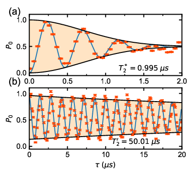
After optimizing the microwave circuits (see Appendix A), we quantified the errors resulting from the fluctuations of the experimental parameters. We assumed that the timescale of and was much longer than that of the single experiment, so the two errors were taken as quasi-static random contrasts. The distribution of was measured by free induction decay (FID) experiments with a pulse sequence in the form of , in which was a rotation around axis by an angle under the rotating frame and was the free evolution time. As shown in Fig. 2(a), oscillatory FID signals were observed with the detuning of MW frequency MHz. We assumed that satisfied a Gaussian distribution, so the probability distribution function is , where stands for the standard deviation of the distribution. The statistical probability that the final state is preserved is
| (2) |
where is the probability of state in a single experiment, is the decay time of FID signals. The fitting results shown in Fig. 2(a) (the blue curve) illustrated that MHz and s.

The error of Rabi frequency was quantified via Rabi experiments where satisfied a Lorentzian distribution of , and stands for the half-width at half-maximum of the distribution and is inversely proportional to the decay time . The results of Rabi experiment are shown in Fig. 2(b). In order to quantify the MW field noise, we adjusted the length of MW pulses from 10 ns to 20 s with an increment of 100 ns. The best fitting result (blue curve in Fig. 2(b)) was achieved with s.
III High-fidelity quantum gates
We demonstrated high-fidelity single-qubit gates implementing four types of pulse sequences, which are square, BB1, CORPSE and ROC, respectively. Their pulse shapes are schematically depicted in Appendix B. Among different types of pulses, square pulses are widely used in quantum control protocols but are not sufficient robust to detunings and Rabi errors. CORPSE and BB1 are both composite pulses; the former can normally resist detunings and the latter is robust against Rabi errors. ROC is a robust shaped pulse optimized by ROC algorithms Haas et al. 2019b which provides a general and effective way to enhance robustness of quantum controls against both MW-frequency detunings and Rabi errors. The procedure of generating a ROC pulse is described in Appendix D.
In order to experimentally verify that ROC is indeed robust with respect to detunings and Rabi errors, an NV electron spin initialized to was irradiated with a pulse, whose carrier frequency was scanned over a range of MHz across resonance and the amplitude was varied within a range of of Rabi frequency. The pulse was generated based on the four different types of pulse shapes, i.e. square, BB1, CORPSE and ROC. The fidelity of -pulse induced state transfer was defined by , where and are the expected density matrix and the realistic density matrix, respectively. The experimental results shown in Fig. 3(b) agrees well with the theoretical fidelity landscapes (see Fig. 3(a)). Among the four types of pulses, it is evident that ROC-based pulse outperforms others in terms of the fidelities over a wide range of detunings and control amplitudes (both of them were more than of Rabi frequency).

IV Randomized Benchmarking
To quantify the fidelity of a quantum gate, one method is the quantum process tomography Childs et al. 2001. However, standard process tomography is limited by errors in the process of state preparation, measurement and single-qubit gates Knill et al. 2008. In addition, due to the fact that error probabilities for quantum gates are of the order of 0.0001 or lower, experimentally detecting such low errors is challenging. Here we use the randomized benchmarking (RB) method Knill et al. 2008 to determine average gate fidelities. In an RB experiment, gate fidelities are evaluated by measuring the fidelity of the final state after random sequences are applied. Errors of state preparations and measurements are separated thus the gate fidelity is determined precisely. The qubit is initialized to state, then a predetermined sequence of randomized computational gates is applied. Each computational gate consists of a Pauli gate and a Clifford gate which are in the form of and respectively, where is chosen randomly in with an identity gate , and is chosen randomly in (see Appendix E). As the number of computational gates increases, the accumulation of gate errors reduces the measured fidelities of final states. The average fidelity of final states is given by Knill et al. 2008:
| (3) |
where is errors of readout and state preparations, is the average fidelity of the NOT gate and is the number of randomized computational gates.
We initialized a single NV spin in and demonstrated RB experiments using three types of pulses (square, BB1 and ROC) under resonant (Fig. 4(a)) and off-resonant conditions (Fig. 4(b)) to quantify gate fidelities precisely. The Rabi frequency was set to be MHz. Under the resonant condition, the average gate fidelities were 0.9994(1) for square, 0.99942(9) for BB1 and 0.99928(7) for ROC respectively, showing no advantages of ROC. While under the off-resonant condition in which detunings and Rabi errors were both set to be of , the highest fidelity of 0.9997(1) was achieved when ROC pulses were applied.
V Detection of nuclear spins
The ROC algorithm is not only effective in designing robust quantum gates, but can also be applied to improve dynamical decoupling sequences in the task of detecting weakly coupled nuclear spins. Nuclear spins exist naturally in abundance in diamonds functioning as additional quantum resources Ladd et al. 2010; Bradley et al. 2019. A prerequisite to exploit nuclear spins’ quantum properties is to detect and characterize the nuclear spins, which can be realized by utilizing the electron spins Taminiau et al. 2012. The Hamiltonian of the NV spin system under the rotating frame is given by Taminiau et al. 2012:
| (4) |
where and are the Hamiltonians of control fields and free evolution respectively. and are amplitude modulations of MW pulses, represents the parallel (transverse) component of hyperfine coupling strength , and is the Larmor frequency of nuclear spins, , and are electron spin operators, and are nuclear spin operators. The Hamiltonian of free evolution can be reformed as:
| (5) |
where is the electron spin state of . It is clear that nuclear spin evolves conditionally according to the electron spin state. Since we performed the experiment at Gauss, under the approximation that , the effective Larmor frequency of nuclear spins is . Thus the effects of the surrounding nuclear spin bath can be considered as an ac signal whose frequency is and amplitude is proportional to acting on the electron spin Taminiau et al. 2012.

| Spin | (kHz) | (degrees) |
|---|---|---|
| 1 | 360(9) | 56(2) |
| 2 | 46(1) | 178.3(5) |
| 3 | 152(5) | 134(2) |
| 4 | 107(1) | 122(1) |
| 5 | 67(4) | 26(1) |
By applying DD sequences (with a basic unit in the form of ) on the electron spin, a resonant peak indicating the coupling between the NV electron spin and the nuclear spin should occur when the interpulse delay ( is odd). However, in realistic experimental implementation, each pulse has a finite width and imperfections, thus when interpulse delay satisfies , phase accumulation occurs during pulses Loretz et al. 2015; Pasini et al. 2011. The phase accumulation at the second harmonic grows as the number of pulses increases and introduces spurious peaks in the detected spectrum, which leads to difficulties in identifying resonance peaks. To avoid false identifications, substantial robust DD sequences have been proposed Genov et al. 2017; Souza et al. 2011; Wang et al. 2019; Casanova et al. 2015; Casanova et al. 2016. When the pulse imperfections are relatively large, our previous theoretical work Yang et al. 2021 indicates that the performance of reported robust DD sequences can be further improved by combining with ROC pulses, resulting in a rather distinguishable spectrum.
Here, we first prepared a single NV electron spin in a superposition by applying a rotational operation about the axis by an angle . After applying the XY8 sequence Gullion et al. 1990 twice (with a basic unit in the form of ), another rotation about the axis by an angle prepared the state to . The resulted population in as a function of was shown in Fig. 5(a). According to the positions and depths of the harmonics, we found five coupled with the electron spin. The coupling strengths and their polar angles were shown in Table. 1. In order to observe the spurious harmonics, we chose the XY4 sequence Gullion et al. 1990 (with a basic unit in the form of ) implemented with square and ROC under an off-resonant condition. Both MW detuning and Rabi error were set to be . By repeating the sequence for 40 times, Fig. 5(b) shows a resonant peak at 0.695 MHz and a spurious peak at 1.39 MHz, which was induced by a strongly coupled nuclear spin (spin 1. in Tab) with its kHz and kHz (Spin 4. in Tab. 1). In comparison, by applying ROC algorithms in DD sequences, the background noise and spurious peaks caused by detunings and Rabi errors can be suppressed significantly, giving rise to a much more clear spectrum (Fig. 5(c)) revealing the electron-nuclear couplings.
VI summary
Noise-resilient quantum gates devised by the robust optimal control algorithm were demonstrated experimentally with considerable improvement of gate fidelities. Unlike hard pulses, shaped pulses with smooth constraints are more friendly to hardware implementation. By generating quantum gates with ROC pulses, the effects of inhomogeneous MW detunings and fluctuations of MW powers were suppressed. In addition, combining DD sequence with ROC pulses suppressed all spurious peaks to a satisfactory extent. Furthermore, this presented approach is fully compatible with other quantum systems, such as superconducting qubits, trapped ions and Rydberg atoms. It would also be an essential technique to be added to the toolbox for improving the sensitivity of solid-state ensemble spin sensors, such as NV centers in diamond, VSi in SiC and organic spin sensors Wu et al. 2022, of which the sensitivities are limited by the inhomogeneous broadening Nöbauer et al. 2015 or the dynamic biological environment Konzelmann et al. 2018.
Acknowledgements.
We thank Tianyu Xie for stimulating discussions. This study was supported by NSF of China (Grant No. 12004037, No. 91859121), Beijing Institute of Technology Research Fund Program for Young Scholars and the China Postdoctoral Science Foundation (Grant No. YJ20210035, No. 2021M700439). X.Y. and J.L. are supported by the National Natural Science Foundation of China (Grants No. 1212200199, No. 11975117, and No. 92065111), Guangdong Basic and Applied Basic Research Foundation (Grant No. 2021B1515020070), Guangdong Provincial Key Laboratory (Grant No. 2019B121203002), and Shenzhen Science and Technology Program (Grants No. RCYX20200714114522109 and No. KQTD20200820113010023).Appendix A Optimization of MW Pulses


In our experiments, manipulations of qubits were achieved by microwave pulses, which were generated by an arbitrary wave generator (AWG70001A, Tektronix), amplified with a power amplifier (ZHL-15W-422-S+, Mini Circuits) and applied through a coplanar waveguide (CPW). In order to minimize the effects induced by both the Overhauser field (caused by interactions with nuclear spin bath) and the distortion of microwave amplitudes (caused by limited bandwidth), we designed and fabricated an ultra-broadband CPW structure with a bandwidth up to 6 GHz Jia et al. 2018. The scattering parameters of the CPW shown in Fig. 6 were measured by a microwave analyzer (N9917A, KeySight).
We found that leakages and reflections between microwave components resulting in extra distortions of microwave pulses, which decreased the fidelity of quantum gates. Figure. 7(a) shew the waveforms of square, CORPSE and BB1. It was apparent that there were distortions at the beginning and the end of pulses. For composite pulses, there were additional distortions between each pulses. Additionally, noise and distortions of phase were found in these pulses (Fig. 7(b)). In order to suppress the distortions and noises, we inserted a 6-dB attenuator at the output port of the microwave source. And at the output port of the power amplifier, we inserted a 6-dB attenuator and an isolator with its frequency bandwidth ranging from 1.42 to 1.54 GHz. Comparisons of the waveforms and phases obtained before and after the circuitry optimization were shown in Fig. 7. The amplitude distortions and phase noises were successfully reduced.
Appendix B High-Fidelity Quantum Gate
We denoted a single-qubit gate as corresponding to a rotation in the rotating frame of angle around the axis in the equatorial plane with azimuth . Waveforms of four types of gate are shown in Fig. 8(b). The CORPSE Cummins et al. 2003b was depicted as , with rotation angles , and . The pulse sequence of BB1 Wimperis 1994 was , where . ROC was generated by robust optimal control methods Yang et al. 2021. Its amplitude and phase varied with time. The in-phase components and quadrature components of the four types of pulses are shown in Fig. 8(a). A pulse with an arbitrary phase angle can be described with .
Appendix C Normalization of Experimental Data

The general experiment schematic is shown in Fig. 9. A 532-nm green laser (MGL-III-532, EFORCE LASERS) was used to polarize the NV center to . Then the pulses generated with the AWG70001A were applied on the qubit. After the microwave pulses, another 532-nm laser pulse was used for readout, and the fluorescence was recorded by the CIQTEK quantum diamond single spin spectrometer. The first photon-counting event recorded as is labelled as ’Sig’ in Fig. 9. The second photon-counting event (’Ref’ in Fig. 9) recorded as is the reference. The experimental data was calculated by , where stands for the averaged value of collected in datasets. The error for each experimental data can be derived according to
| (6) |
where and denote standard deviations of and respectively. In general, a quantum state tomography Childs et al. 2001; Leskowitz and Mueller 2004 is normally used to get fidelity of final state. However, in our experiments, final states were either or , so we only needed to figure out the diagonal elements of the density matrix. Normalization of the experimental data was carried out by performing Rabi experiments. By fitting the data obtained from Rabi experiments with a sinusoidal function, the probability of achieving state was given by:
| (7) |
where and were the maximum and minimum values of the fitted curve.

Appendix D Robust Optimal Control
The robust optimal control method that we adopted in our work is based on Ref. Yang et al. 2021. Here we plot a flow chart (see Fig. 10) to show the procedure of generating a ROC pulse. The procedure starts from initializing some parameters including (1) the operator to be optimized (here we take ); (2) the pulse length ; (3) two weights of noise, for detunings and for Rabi errors; (4) the maximum order of directional derivatives ; (5) a set of weights specifying the importance of the associated objective function . Then according to the results of evolution simulation, the fitness function is calculated by:
| (8) |
If is sufficiently high, the shaped pulse is output, otherwise, the gradient of the fitness function with respect to the pulse parameters is computed. By determining an appropriate step length along the search direction , we update the pulse parameters and go back to the simulation step.
Appendix E Randomized Benchmarking
The randomized benchmarking (RB) method Knill et al. 2008 consists of a large number of experiments. Each experiment includes the preparation of an initial state , application of an alternating sequence of "Pauli gate" and "Clifford gate", and measuring final states. The Pauli gates consist of unitary operators which are in the form of , where and and is defined as an identity operator. The Clifford gates are pulses represented by , with . The sign and are chosen uniformly at random except for the last pulse, which is chosen to ensure that the final state is either or . The length of a randomized pulse sequence is its number of the pulses. By performing the experiment times for each length , the averaged state fidelity is estimated. The average gate fidelity can be derived from the relationship between and , which is given by Knill et al. 2008
| (9) |
where combines the errors of the preparation and measurement, and represents the average fidelity of the NOT gate.
Measurement statistics for experiments is obtained with the RB method, where is the number of different computational gate sequences, is the number of lengths to which the sequences are truncated, is the number of Pauli randomizations for each gate sequence, and is the number of experiments for each specific sequence. The steps of generating randomized sequences are given by Knill et al. 2008:
- 1.
Pick a set of lengths and do the following for each :
- (a)
Choose a random sequence of computational gates.
- (b)
For each , do the following:
- i.
Figure out the final state by applying ideal sequence to .
- ii.
Randomly pick a final gate among the two axis pulses applied to to ensure the final state is an eigenstate of .
- iii.
Do the following for each :
- A.
Choose a random sequence of Pauli pulses.
- B.
Generate the sequence as . Record the idea final state when applying this sequence to . Experimentally demonstrate the sequence on , repeating times.
- C.
From the experimental data and the expected final state, obtain an estimate of the state fidelities.
- A.
- i.
- (a)
References
- Chou et al. (2015) Y. Chou, S.-Y. Huang, and H.-S. Goan, Optimal control of fast and high-fidelity quantum gates with electron and nuclear spins of a nitrogen-vacancy center in diamond, Phys. Rev. A 91, 052315 (2015).
- Khaneja et al. (2005) N. Khaneja, T. Reiss, C. Kehlet, T. Schulte-Herbrüggen, and S. J. Glaser, Optimal control of coupled spin dynamics: design of nmr pulse sequences by gradient ascent algorithms, J. Magn. Reson. 172, 296 (2005).
- Van Reeth et al. (2017) E. Van Reeth, H. Ratiney, M. Lapert, S. J. Glaser, and D. Sugny, Optimal control theory for applications in magnetic resonance imaging, Pac J Math 9, 9 (2017).
- Fuchs et al. (2011) G. Fuchs, G. Burkard, P. Klimov, and D. Awschalom, A quantum memory intrinsic to single nitrogen–vacancy centres in diamond, Nat. Phys. 7, 789 (2011).
- Waldherr et al. (2014) G. Waldherr, Y. Wang, S. Zaiser, M. Jamali, T. Schulte-Herbrüggen, H. Abe, T. Ohshima, J. Isoya, J. Du, P. Neumann, et al., Quantum error correction in a solid-state hybrid spin register, Nature 506, 204 (2014).
- Neumann et al. (2010) P. Neumann, R. Kolesov, B. Naydenov, J. Beck, F. Rempp, M. Steiner, V. Jacques, G. Balasubramanian, M. Markham, D. Twitchen, et al., Quantum register based on coupled electron spins in a room-temperature solid, Nat. Phys. 6, 249 (2010).
- Häberle et al. (2013) T. Häberle, D. Schmid-Lorch, K. Karrai, F. Reinhard, and J. Wrachtrup, High-dynamic-range imaging of nanoscale magnetic fields using optimal control of a single qubit, Phys. Rev. Lett. 111, 170801 (2013).
- Shi et al. (2014) F. Shi, X. Kong, P. Wang, F. Kong, N. Zhao, R.-B. Liu, and J. Du, Sensing and atomic-scale structure analysis of single nuclear-spin clusters in diamond, Nat. Phys. 10, 21 (2014).
- Shi et al. (2015) F. Shi, Q. Zhang, P. Wang, H. Sun, J. Wang, X. Rong, M. Chen, C. Ju, F. Reinhard, H. Chen, et al., Single-protein spin resonance spectroscopy under ambient conditions, Science 347, 1135 (2015).
- Aslam et al. (2017) N. Aslam, M. Pfender, P. Neumann, R. Reuter, A. Zappe, F. F. De Oliveira, A. Denisenko, H. Sumiya, S. Onoda, J. Isoya, et al., Nanoscale nuclear magnetic resonance with chemical resolution, Science 357, 67 (2017).
- Cerrillo et al. (2021) J. Cerrillo, S. Oviedo Casado, and J. Prior, Low field nano-nmr via three-level system control, Phys. Rev. Lett. 126, 220402 (2021).
- Soshenko et al. (2021) V. V. Soshenko, S. V. Bolshedvorskii, O. Rubinas, V. N. Sorokin, A. N. Smolyaninov, V. V. Vorobyov, and A. V. Akimov, Nuclear spin gyroscope based on the nitrogen vacancy center in diamond, Phys. Rev. Lett. 126, 197702 (2021).
- Rembold et al. (2020) P. Rembold, N. Oshnik, M. M. Müller, S. Montangero, T. Calarco, and E. Neu, Introduction to quantum optimal control for quantum sensing with nitrogen-vacancy centers in diamond, AVS Quantum Sci. 2, 024701 (2020).
- Levitt (1986) M. H. Levitt, Composite pulses, Prog. Nucl. Magn. Reson. Spectrosc. 18, 61 (1986).
- Wimperis (1994) S. Wimperis, Broadband, Narrowband, and Passband Composite Pulses for Use in Advanced NMR Experiments, J. Magn. Reson. 109, 221 (1994).
- Cummins et al. (2003a) H. K. Cummins, G. Llewellyn, and J. A. Jones, Tackling systematic errors in quantum logic gates with composite rotations, Phys. Rev. A 67, 042308 (2003a).
- Rong et al. (2015) X. Rong, J. Geng, F. Shi, Y. Liu, K. Xu, W. Ma, F. Kong, Z. Jiang, Y. Wu, and J. Du, Experimental fault-tolerant universal quantum gates with solid-state spins under ambient conditions, Nat. Commun. 6, 8748 (2015).
- Yang et al. (2021) X. Yang, Y. Ge, B. Zhang, and J. Li, Robust dynamical decoupling for the manipulation of a spin network via a single spin, arXiv preprint arXiv:2101.03976 (2021).
- Haas et al. (2019a) H. Haas, D. Puzzuoli, F. Zhang, and D. G. Cory, Engineering effective hamiltonians, New J. Phys. 21, 103011 (2019a).
- Haas et al. (2019b) H. Haas, D. Puzzuoli, F. Zhang, and D. G. Cory, Engineering effective hamiltonians, New J. Phys. 21, 103011 (2019b).
- Childs et al. (2001) A. M. Childs, I. L. Chuang, and D. W. Leung, Realization of quantum process tomography in nmr, Phys. Rev. A 64, 012314 (2001).
- Knill et al. (2008) E. Knill, D. Leibfried, R. Reichle, J. Britton, R. B. Blakestad, J. D. Jost, C. Langer, R. Ozeri, S. Seidelin, and D. J. Wineland, Randomized benchmarking of quantum gates, Phys. Rev. A 77, 012307 (2008).
- Ladd et al. (2010) T. D. Ladd, F. Jelezko, R. Laflamme, Y. Nakamura, C. Monroe, and J. L. O’Brien, Quantum computers, Nature 464, 45 (2010).
- Bradley et al. (2019) C. E. Bradley, J. Randall, M. H. Abobeih, R. C. Berrevoets, M. J. Degen, M. A. Bakker, M. Markham, D. J. Twitchen, and T. H. Taminiau, A ten-qubit solid-state spin register with quantum memory up to one minute, Phys. Rev. X 9, 031045 (2019).
- Taminiau et al. (2012) T. H. Taminiau, J. J. T. Wagenaar, T. van der Sar, F. Jelezko, V. V. Dobrovitski, and R. Hanson, Detection and control of individual nuclear spins using a weakly coupled electron spin, Phys. Rev. Lett. 109, 137602 (2012).
- Loretz et al. (2015) M. Loretz, J. M. Boss, T. Rosskopf, H. J. Mamin, D. Rugar, and C. L. Degen, Spurious harmonic response of multipulse quantum sensing sequences, Phys. Rev. X 5, 021009 (2015).
- Pasini et al. (2011) S. Pasini, P. Karbach, and G. S. Uhrig, High-order coherent control sequences of finite-width pulses, Europhys. Lett. 96, 10003 (2011).
- Genov et al. (2017) G. T. Genov, D. Schraft, N. V. Vitanov, and T. Halfmann, Arbitrarily accurate pulse sequences for robust dynamical decoupling, Phys. Rev. Lett. 118, 133202 (2017).
- Souza et al. (2011) A. M. Souza, G. A. Álvarez, and D. Suter, Robust dynamical decoupling for quantum computing and quantum memory, Phys. Rev. Lett. 106, 240501 (2011).
- Wang et al. (2019) Z.-Y. Wang, J. E. Lang, S. Schmitt, J. Lang, J. Casanova, L. McGuinness, T. S. Monteiro, F. Jelezko, and M. B. Plenio, Randomization of pulse phases for unambiguous and robust quantum sensing, Phys. Rev. Lett. 122, 200403 (2019).
- Casanova et al. (2015) J. Casanova, Z.-Y. Wang, J. F. Haase, and M. B. Plenio, Robust dynamical decoupling sequences for individual-nuclear-spin addressing, Phys. Rev. A 92, 042304 (2015).
- Casanova et al. (2016) J. Casanova, Z.-Y. Wang, and M. B. Plenio, Noise-resilient quantum computing with a nitrogen-vacancy center and nuclear spins, Phys. Rev. Lett. 117, 130502 (2016).
- Gullion et al. (1990) T. Gullion, D. B. Baker, and M. S. Conradi, New, compensated carr-purcell sequences, J. Magn. Reson. (1969-1992) 89, 479 (1990).
- Wu et al. (2022) H. Wu, S. Yang, M. Oxborrow, Q. Zhao, B. Zhang, and J. Du, Enhanced quantum sensing with room-temperature solid-state masers, arXiv preprint arXiv:2201.04298 (2022).
- Nöbauer et al. (2015) T. Nöbauer, A. Angerer, B. Bartels, M. Trupke, S. Rotter, J. Schmiedmayer, F. Mintert, and J. Majer, Smooth optimal quantum control for robust solid-state spin magnetometry, Phys. Rev. Lett. 115, 190801 (2015).
- Konzelmann et al. (2018) P. Konzelmann, T. Rendler, V. Bergholm, A. Zappe, V. Pfannenstill, M. Garsi, F. Ziem, M. Niethammer, M. Widmann, S.-Y. Lee, et al., Robust and efficient quantum optimal control of spin probes in a complex (biological) environment. towards sensing of fast temperature fluctuations, New J. Phys. 20, 123013 (2018).
- Jia et al. (2018) W. Jia, Z. Shi, X. Qin, X. Rong, and J. Du, Ultra-broadband coplanar waveguide for optically detected magnetic resonance of nitrogen-vacancy centers in diamond, Rev. Sci. Instrum. 89, 064705 (2018).
- Cummins et al. (2003b) H. K. Cummins, G. Llewellyn, and J. A. Jones, Tackling systematic errors in quantum logic gates with composite rotations, Physical Review A 67 (2003b).
- Wimperis (1994) S. Wimperis, Broadband, narrowband, and passband composite pulses for use in advanced nmr experiments, J. Magn. Reson., Ser. A 109, 221 (1994).
- Leskowitz and Mueller (2004) G. M. Leskowitz and L. J. Mueller, State interrogation in nuclear magnetic resonance quantum-information processing, Phys. Rev. A 69, 052302 (2004).