High fidelity fluid-structure interaction by radial basis functions mesh adaption of moving walls: a workflow applied to an aortic valve
Abstract
Fluid-Structure Interaction (FSI) can be investigated by means of non-linear Finite Element Models (FEM), suitable to capture large deflections of structural parts interacting with fluids, and Computational Fluid Dynamics (CFD). High fidelity simulations are obtained using the fine spatial resolution of both the structural and fluid computational grids. A key enabler to have a proper exchange of information between the structural solver and the fluid one is the management of the interface at wetted surfaces where the grids are usually non matching. A class of applications, known also as one-way FSI problems, involves a complex movement of the walls that is known in advance as measured or as computed by FEM, and that has to be imposed at the boundaries during a transient CFD solution. Effective methods for the time marching adaption of the whole computational grid of the CFD model according to the evolving shape of its boundaries are required. A very well established approach consists of a continuum update of the mesh that is regenerated by adding and removing cells to fit the evolution of the moving walls. In this paper, starting from the work originally presented in Meshfree Methods in Computational Sciences, ICCS 2020 [1], an innovative method based on Radial Basis Functions (RBF) mesh morphing is proposed, allowing the retention of the same mesh topology suitable for a continuum update of the shape. The proposed method is exact at a set of given key configurations and relies on shape blending time interpolation between key frames. The study of the complex motion of a Polymeric-Prosthetic Heart Valve (P-PHV) is presented using the new framework and considering as a reference the established approach based on remeshing.
Keywords:
Morphing Radial basis functions Multi-physics Fluid-Structure Interaction Polymeric Aortic Valve1 Introduction
In all the engineering areas of development, multi-physics analysis appears highly difficult to be carried out because of the interactions between more than one physics involved. During the achievement and the analysis of coupled systems, the way in which the shape of the object influences its performances is required to be carefully taken into account. In the biomedical engineering field for example, the design and the evaluation of the behaviour of prosthetic valves, stent-grafts and ventricular assist devices are related to both the structural and fluid mechanics physics [2, 3, 4]. Generally speaking, numerical meshes need to be created for the specific kind of analysis and, in a multi-physics context, two or more meshes have to be realised. In this environment, each geometric change is applied to all the numerical models involved in the analysis: such update has to be performed in a rapid way and as easy as possible. This task, usually carried out through remeshing methods, may also be obtained faster with the use of mesh morphing techniques. This approach allows the changing of the shape of a meshed surface so that the topology is preserved while nodal positions are updated [5, 6]: modifications are applied on a baseline grid by moving the surface nodes and propagating displacements inside the surrounding volume mesh nodes. Concerning biomedical applications, morphing methods have been applied in both bone and cardiovascular fields. Recently, in [7], an interactive sculpting and RBF mesh morphing approach has been proposed to address geometry modifications using a force-feedback device, while in [8] RBF have been applied to improve cranioplasty applications. In the cardiovascular field, morphing approaches were employed in [9] for the registration procedures of the cardiac muscle and to model an aorta aneurysm by exploiting a one-way FSI [10, 11, 12]. In literature RBF have been extensively employed to tackle FSI problems [13], using the modal method for both static [14, 15] and transient simulations [16, 17, 18], as well as the two-way approach [19, 20] with RBF-based mapping methods [21]. In this work the state of the art regarding biomedical one-way FSI applications, as shown in [12], is further improved for a transient simulation by taking into account the non-linear deformations of the wetted surfaces during motion. An ad-hoc workflow was developed to transfer and to update, using an RBF-based morphing technique, the CFD mesh, incrementally adjusting the geometry according to the non-linear evolution predicted by the FEM solver. To demonstrate the effectiveness of the proposed approach, it was applied to a tailor-made Polymeric-Prosthetic Heart Valve (P-PHV); these devices [22] proved to significantly reduce blood coagulation problems, maintaining excellent properties in term of strength, efficient function and long-term durability [23, 24]. This work is arranged as follows: at first, an introduction on FSI coupling is given, comparing remeshing and morphing workflows. The proposed procedure is implemented in the following paragraph, in which the incremental approach is shown in the P-PHV case. Results are finally discussed and compared with those obtained by remeshing.
2 FSI coupling: known-imposed motion of the walls
One of the most sensitive processes in a Fluid-Structure Interaction analysis concerns the management of the fluid-solid interfaces; at the boundary surfaces between these two domains, solution data is shared between the fluid solver and the structural one. In the most rigorous FSI approach, a bidirectional coupling between structural and fluid dynamic solutions is involved in an iterative process. Such so called 2-way coupling introduces both the complexity related to the proper mapping of loads between the common boundaries of the two numerical domains (which are discretized by non-conformal meshes), and the requirement of an efficient procedure able to adapt the fluid dynamic domain to the structural solution in terms of boundaries displacement. When the target displacement is known, or the deformation is weakly affected by the aerodynamic loads, the procedure can progress in a single direction consisting of matching the CFD domain boundaries according to the target geometry. This one-way coupling does not guarantee energy conservation at the fluid-solid interface but holds the benefit of lower computational time in comparison with the bidirectional one, in which a continuous data exchange between Computational Structural Mechanics (CSM) and CFD solvers is required. The uncertainties introduced by the mapping procedure are avoided, as well as the development of procedures governing the computations and the communications between different numerical environments. Several strategies are possible to link the computational domain to target shapes. A useful technique consists in describing the geometry adopting CAD based mathematical representations of surfaces, as Non-Uniform Rational B-Splines (NURBS). The aim is to provide a parametric formulation of the model that, adopting opportune mapping procedures, is able to reconstruct complex shapes derived from images as medical CTA data [25]. This approach, introduced in 2005 [26], is called Isogeometric Analysis (IgA). In [27], such parametric design platform is coupled with the concept of immersed boundary [28] referring to the so called Immersogeometric FSI analysis. Immersed boundary approach, in combination with a rigid dynamic solution of a bi-leaflets mechanical heart valve, is considered in [29]. An example of a dynamic Immersogeometric analysis applied to the FSI analysis of a bio-prosthetic heart valves is reported in [30].
The implementation of overset meshes (also called Chimera grids) to perform aeroelastic analyses offers several advantages. It allows to decompose the mesh generation problem to limited portions of domain and simplifies the adoption of structured meshes which allow, with respect to unstructured/hybrid meshes, a better control of the cells clustering, the generation of high quality domains and the provision of more accurate solutions of boundary layers. An example of the application of overset grid methodologies in fluid-structure interaction (FSI) problems is reported in [31].
As introduced, a common strategy to tackle the geometric adaptation problem consists in implementing this action directly in the numerical domain by mesh morphing techniques. Some of the most important advantages offered by this approach are: it does not require a remeshing procedure, it allows to preserve the robustness of the computation and it can be performed within the progress of the computation. The quality of the morphing action depends on the algorithm adopted to smooth the volume. One of the most efficient mathematical framework to perform this task is recognized to be based on Radial Basis Functions.
In this work two Arbitrary Lagrangian Eulerian (ALE) methods [32, 33, 34] for moving meshes are employed: the first based on remeshing algorithms, called in this paper “standard”approach and the novel one using RBF mesh morphing procedures.
2.1 FSI analysis based on remeshing

In this first kind of analysis, as shown in Fig. 1, a specific component is responsible to transfer the deformation of the CSM mesh to the grid of the CFD solver. In fact, one of the most applied strategies to manage body meshes in FSI applications is simply to move the grid for as long as possible and, when the quality of the mesh becomes poor, to enable the remeshing tools updating the low-quality cells generated by high displacements in the fluid domain [35]. The larger the displacements of the grid, the greater the distortions of the cells; remeshing method agglomerates cells that violate the initially defined Skewness [36] or size criteria and remeshes them. If the new cells or faces satisfy the Skewness criterion, the mesh is locally updated with the new cells, interpolating the solution from the old cells. Otherwise, the new cells are discarded and another remeshing step is required. Obviously, when small displacements are involved and just few remeshing steps are necessary, this approach may be considered efficient. However, for larger displacements, the number of remeshing steps increases to avoid the presence of negative and invalid elements; as a result, the simulation is slowed down because a new mesh with different numbers and positions of nodes and cells has to be generated more frequently.
2.2 A novel FSI workflow using RBF mesh morphing
To overcome the problems related to remeshing, a procedure based on mesh morphing to adapt the shape according to a target one [37] is described. Among the morphing methods available in the literature, RBF are well known for their interpolation quality also on very large meshes [5, 38, 39]. RBF allow to interpolate everywhere in the space a scalar functions known at discrete points, called Source points (Sp). By interpolating three scalar values it is possible, solving a linear system of order equal to the number of Sp employed [5], to describe a displacement of the Sp in the three directions in space. The interpolation function is defined as follows:
| (1) |
where is a generic position in space, the Sp position, the scalar function which represents a transformation , the radial function of order , the weight and a polynomial term with degree that can be omitted, but in this case is added in order to improve the fit, assuring uniqueness of the problem and an exact interpolation of fields of the same form of .
The unknowns of the system, namely the polynomial coefficients and the weights of the radial functions, are retrieved by imposing the passage of the function on the given values and an orthogonality condition on the polinomials. If the RBF is conditionally positive definite, it can be demonstrated that a unique interpolant exists and in 3D, if the order is equal or less than 2, a linear polynomial in the form can be used. The linear problem can be also written in matrix form:
| (2) |
in which M is the interpolation matrix containing all the distances between RBF centres , P the matrix containing the polynomial terms that has for each row the form and g the known values at Sp. The new nodal positions, if interpolating the displacements, can be retrieved for each node as:
| (3) |
where and are the vectors containing respectively the updated and original positions of the given node.
As the problem is solved pointwise, the approach is meshless and able to manage every kind element (tetrahedral, hexahedral, polyhedral and others), both for surface and volume mesh smoothing ensuring the preservation of their topology.

In general, a morphing operation can introduce a reduction of the mesh quality but a good morpher has to minimize this effect and to maximize the possible shape modifications. If mesh quality is well preserved, morphing has a clear benefit over remeshing because it avoids introducing noise [5]. This procedure provides for the sampling of the displacements of the structural model. In this way, the surface nodes of the FE model are used as Sp to apply RBF mesh morphing in the space. The detailed workflow shown in Fig. 2, in addition to the realization of the geometric model, provides for three main steps:
- -
CSM settings
- -
RBF Morph application
- -
CFD set-up
CSM settings.
Given that in this kind of FSI analysis the deformations of the fluid grid are imposed by the motion of the walls of the CSM domain, a structural simulation has to be conducted to obtain the deformed positions in the space during time. During the structural simulation, Source points () and Target points (), that are the surface nodal positions of the grid in this case, are recursively extracted and stored in files. These files are structured as a list of nodes and the related displacements to obtain the nodes in the following sampled configuration.
RBF Morph application.
To apply the shape deformation without remeshing, the morpher RBF Morph is in this study employed [40]. To delimit the morphing action, an encapsulation technique has to be implemented, defining in this way sub-domains or parts of the fluid domain within which the morpher action is applied [41]. According to [42], effectively used are a random subgroup which includes a percentage close to 2% of the total extracted surface nodes of the structural model. A Radial Basis Function is selected and, when the settings of the procedure are completed, morphing solutions are calculated, each per morphing transitions, from the starting configuration to the final position of the model. Every transition, a new deformed mesh is generated and the solution files are stored.
CFD set-up.
Once all the morphed meshes are obtained, the CFD analysis is carried out every time step on a new deformed mesh, by using a specific script containing the RBF functions to update the nodal positions. The script is run before the starting of the CFD simulation and it allows the automatization of the MultiSol tool of RBF Morph software in order to guarantee the synchronous implementation of the deformed shape in fluid environment. The nodal displacement inside two subsequent morphed positions is simply handled inside the Scheme script by means of a parameter called amplification A(t) which varies over time from 0 to (usually equal to +1 or -1). Due to the sampling data available at different times, an accurate and effective solution can be obviously achieved, handling all the morphing deformations separately and linearly modulating the amplification within each of the sampled grids: calling the index that concerns all the mesh conformations …, the amplification inside each time step can be evaluated as:
| (4) |
In this way, the fluid grid is able to follow the displacements of the CSM mesh and solution can be quickly calculated every time step on a new deformed grid. In other situations, not only linear amplifications but also quadratic and sinusuoidal ones can be used to manage motion through morphing, to replicate more correctly the studied dynamics.
3 Implementation of the workflows to study the opening phase of a polymeric aortic valve
In this paper, both the presented FSI solution approaches are applied to study the opening phase of a P-PHV. This kind of analysis is conducted on a prosthetic valve to study its haemodynamic behaviour during the opening phase in which the leaflets or cusps [43, 44] are pushed open to allow the ejection of the blood flow and to investigate the effects of the solid domain (P-PHV) on the fluid domain (blood flow).
The design of a prosthetic aortic valve is realised using the software SpaceClaim, following the geometry proposed in [45], and then imported inside ANSYS Workbench (v193). Fig. 3 depicts the CAD model of the polymeric valve here investigated and the fluid domain of the blood in which also the Valsalva sinuses are represented [46]. This fluid domain is obtained by a boolean intersection between the solid domain of the valve and a vessel made up of an inlet and outlet tube.

The computational grid of this structural model is made up of 300,000 tetrahedral elements and it is obtained inside ANSYS Meshing. The material chosen to model the valve is isotropic linear elastic with a Young’s modulus of 3 MPa, and a Poisson’s ratio of 0.4. The mesh of the fluid domain is obtained inside Ansa (v20.0.1) and made up of 1.56 million tetra-hexaedral elements with a maximum starting Skewness (Sk) of 0.694. A velocity inlet and a systolic aortic pressure outlet varying over time boundary conditions have been provided. The flow model selected is Viscous-Laminar and the fluid is considered as incompressible and Newtonian with a viscosity of 4 cP.
3.1 Study of the valve using the remeshing workflow

The workflow of the first approach based on remeshing and implemented inside ANSYS Workbench is proposed in Fig. 4. In this case, the displacements of a transient CSM in ANSYS Mechanical (v193) are transferred to the fluid domain inside ANSYS Fluent (v193) by means of System Coupling. The body of the prosthetic device is fixed at its bottom surface. Concerning the loads, a physiological time-varying pressure is uniformly applied to the ventricular portion of the valve to simulate the opening pressure.
Fluent was used as the CFD solver, the Dynamic Mesh option was activated to deform and regenerate the computational grid [47]: the Spring-based Smoothing Method and the Remeshing Method, two tools to solve the analysis of deformed domains due to boundary movement over time [48], are applied.
Inside the System Coupling component, all the surfaces of the valve in contact with the blood are set as fluid-solid interfaces and a time step of s is selected. For the run, 48 cores of Intel(R) Xeon(4) Gold 6152 @2.10 GHz and a 256 Gb RAM are used.
3.2 Study of the valve using the morphing approach

The novel workflow, based on a RBF mesh morphing, also in this case developed into the ANSYS Workbench environment is shown in Fig. 5 which depicts the overall incremental procedure; in particular, the System Coupling component, fundamental in the previously shown approach, is not employed here.
Results obtained with the use of RBF Morph software are compared with those achieved using Fluent remeshing tools. They are reported in terms of pressure map, velocity streamlines, 2D velocity contours on a section plane A-A (Fig. 6) and computational time.

Structural simulations.
The same CSM analysis implemented in the remeshing approach with the same time-varying physiological pressure is conducted. A specific Application Customization Toolkit (ACT) Extension, i.e. a method to achieve custom applications inside ANSYS Mechanical, is developed to extract the deformed configurations of the leaflets and collect Sp and Tp according to a sampling time chosen by the user: in this first case, ten different surface nodal positions (…) are collected sampling every 2 ms (0-18 ms).
RBF Morph set-up.
The RBF Morph Fluent (v193) Add-On is adopted: the RBF are used to step by step project the to the and interpolate the displacements of the volume nodes inside the blood domain over time. RBF Morph tools may impose a blood domain adaptation in the CFD analysis following the deformed shapes of the valvular domain, extracted from the previous CSM simulation. In the case of the valve, to control the morphing action in the space, no encapsulation volumes [41] are generated but a fixed Surf Set (with null displacement during the movement of the leaflets) on the wall of the Sinotubular Junction (STJ) [49] is preferred (Fig. 7). In this way, since the distortion of the mesh is extremely high, such deformations can be distributed also in the other zones of the fluid domain and not only in proximity to the valve.

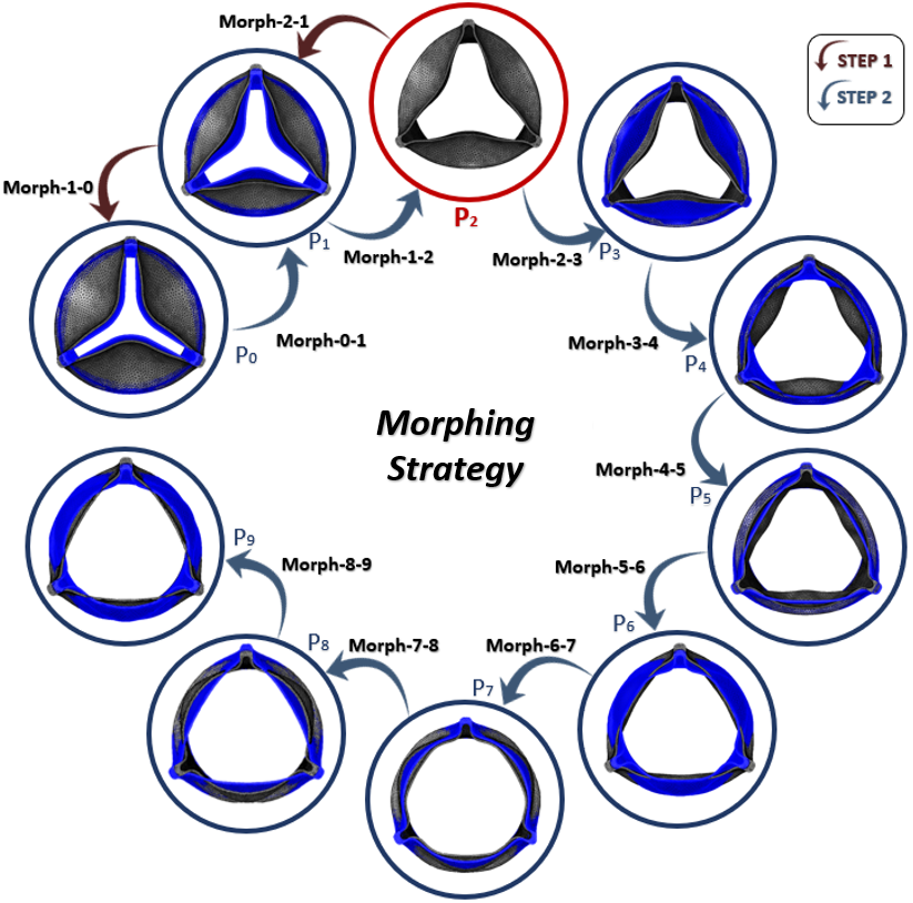
To prevent mesh quality reduction, in this work the bi-harmonic kernel is used: it is the RBF that guarantees to keep the mesh quality degradation at minimum [50]. The nine solutions are calculated using the Solve Panel of the software, each per morphing action. Two different strategies are evaluated:
- •
Forwards: from (initial position) directly to (totally open position).
- •
Backwards/Forwards (Fig. 8): extracting a new already deformed valve in position of which a new mesh is achieved, from going back to (backwards - step 1) and then from moving on to (forwards - step 2).
The first strategy produced an excessive mesh distortion with negative cells volume in particular at the centre of the leaflets. No mesh problems are detected with the adopted second approach as it started from a robust mesh in intermediate configuration that was modified partly to return to the initial position and partly to reach the full opening phase.
Fluent setting.
The same time step of the standard approach ( s) is selected. The flow is initialized with the valve in position and the Scheme file with the amplification of each of the nine different transitions is inside Fluent. The amplification used for the displacements between and is linear as shown in (4). Instead, the use of a quadratic amplification between and is preferred in order to more realistically replicate the rapid opening of the prosthesis:
| (5) |
Using to this workflow, the FSI simulation can be conducted only by means of this CFD analysis in which the mesh is updated every time step.
3.3 Full systolic movement using RBF mesh morphing
Given that morphing is found to be several times faster than remeshing tools, a complete opening cycle of the valve for a total of 130 ms is simulated, allowing the valve not only to open but also to provide for all the cardiac ejection and return to a position close to the initial one. For these reasons, a new structural simulation is carried out on the same 130 ms to allow the extraction of further surface nodes during time: ten additional valvular positions are sampled after the systolic peak, corresponding to the descending portion of the inlet velocity curve reported in Fig. 9, in which the valve begins closing and it comes back in a position similar to the initial one. In Fig. 10, the time in which the morphing positions are sampled is reported in detail. Once opened, the P-PHV starts weakly swinging; all these small vibrations can be neglected in term of variation of Geometric Orifice Area (GOA), as shown in [51, 52]. This means that the conformation of the valve between and remains quite similar, that’s why no samples are taken in this interval (18 ms - 58 ms). Moreover, since the movement of the valve is slower in the section between the systolic peak and the beginning of the diastole than the more abrupt opening at the beginning of the systole, as reported in [53], positions samplings may take place every 8 milliseconds and not every 2, thus saving computational time for morphing transformations.
Time step selected for this simulation is s.


4 Results and Discussions
4.1 Remeshing and morphing results
The first important parameter to check in the implementation of both the approaches is the Skewness: no negative cells are detected and maximum Sk values are 0.858 and 0.961 respectively for the procedure implemented through remeshing and morphing. No convergence issues due to mesh degradation are recorded.
In this work, pressure and velocity results of the 3D-model at a specific and significant time step are shown using the CFD-Post software. In addition, a case comparison between the velocity contours on the A-A section plane at 4 different time instants is carried out to evaluate the differences between the two techniques presented.

Pressure map - A 3D-pressure rendering at the time in which the valve is for the first time open (7 ms) is represented in Fig. 11; as can be observed, no significant differences in terms of pressure values are recorded between the two approaches: the mean pressure are 69.64 mmHg and 70.31 mmHg respectively for the simulation based on remeshing and the analysis using mesh morphing (difference of less than 1%).
Velocity streamlines - Streamlines of both the solution methods are reported in Fig. 12. It is possible to observe how in this 3D-representation the local maximum values are placed in the same zones. Maximum local fluid velocities are reached right at t=7 ms because the fast movement of the leaflets pushes away the blood: maximum value for the FSI implemented with the novel approach is 3.011 m/s, about 5.6% less than the value detected in the analysis based on remeshing, that is 3.189 m/s.

Velocity contours - To investigate in more depth the differences between remeshing and morphing, velocity contours on the plane passing through the centre of the valve, shown in Fig. 6, are evaluated. Four different evenly spaced time steps are here reported (Fig. 13): 3 ms, 7 ms, 11 ms, 15 ms. To better identify these differences, in the same picture the case comparison by exploiting the subtraction in absolute value between the velocity of remeshing and morphing is also evaluated. The numerical results of interest are reported in Table 1. Here, maximum and average velocity values on the section plane A-A for both the approaches are evaluated. The local maxima in both cases are significantly above the physiological values normally found. This is due to the motion imposed on the valve which pushes strongly fluid close to the leaflets during opening. Moreover, the high difference that emerges from the image with the case comparison is mainly attributable to the difference between local maxima moved slightly in the 2-D space. The maximum difference detected between the maximum values occurs after 11 milliseconds when the morphing value is 6.4 lower than that of remeshing. In the case of the average value, the highest gap is at t=15 ms: in this case, the FSI carried out by means of morphing returns a value 0.063 times lower than the simulation with remeshing. However, despite a very high stretching of the elements, there are no marked irregularities in the case of mesh morphing.

| TIME | Max. velocity remeshing | Max. velocity morphing | Difference between Max. |
|---|---|---|---|
| t=3 ms | 0.388 | 0.381 | -0.007 (-1.8) |
| t=7 ms | 3.004 | 2.937 | -0.067 (-2.2) |
| t=11 ms | 3.432 | 3.211 | -0.221 (-6.4) |
| t=15 ms | 2.216 | 2.088 | -0.128 (-5.8) |
| TIME | Ave. velocity remeshing | Ave. velocity morphing | Difference between Ave. |
|---|---|---|---|
| t=3 ms | 0.081 | 0.079 | -0.002 (-2.4) |
| t=7 ms | 0.289 | 0.294 | +0.005 (+1.7) |
| t=11 ms | 0.456 | 0.434 | -0.022 (-4.8) |
| t=15 ms | 0.788 | 0.738 | -0.050 (-6.3) |
Computational time - The time required to run the simulation is the most interesting difference between these two solution methods: with the same number of elements and parity of time step ( s), the standard workflow requires 6283 minutes to solve the problem while the CFD analysis with the morphing application only 396 minutes, approximately 16 times faster. Furthermore, if time step is increased, Fluent solver using remeshing starts having troubles and the obvious consequence is the non convergence of the model. This phenomenon does not happen with morphing for which the time step can be increased significantly without problems and solution time can be reduced up to 60 times compared with that of remeshing.
4.2 Global systolic phase simulated through mesh morphing
The simulation with the motion of the walls imposed on the entire systolic phase is correctly completed by means of mesh morphing. The velocity contours computed on plane A-A (Fig. 6) and the 3D representations of the P-PHV are shown in Fig. 14. As it can be seen, after 20 ms, the propagation of the blood flow is still strongly affected by the abrupt opening of the valve itself and the local maxima of velocity are located exclusively in proximity of the leaflet. Near the systolic peak instead, the highest velocity region is more evenly distributed in the central orifice area of the valve as the leaflets have now completed their opening and no longer push fluid against the sinuses of Valsalva. At t=80 ms, passed the flow peak, the valve is already starting to close reducing its orifice area while after 110 ms the prosthesis is very close to achieving the final configuration: in this case, as it can be seen, the 2D velocity contour distribution is very similar to the one shown after 3 ms in Fig. 13.
By means of the new time step and through mesh morphing, 311 minutes are required to run the simulation.

5 Conclusions
In this work, a fast high fidelity workflow for a multi-physics Fluid-Structure Interaction analysis exploiting ANSYS Workbench and RBF Morph is presented. In particular, this powerful system has proved to be useful and accurate in all those applications for which the movement of the fluid domain is strongly controlled by the deformation of the solid one as in the case of valves or bodies, in contact with a fluid, whose motion is known or imposed. The possibility to replicate the non-linear analysis in which the motion of a solid model is transferred to a fluid domain carefully handling the interfaces is demonstrated. In a specific application case, the attempt to transfer aortic valve opening kinematics to the CFD analysis through a mesh morphing technique is successful and the effectiveness of the FSI simulation implemented through mesh morphing to reproduce the fluid dynamic field of the aortic valve is here shown and validated. Morphing has turned out to be very consistent in comparison with remeshing. Further research is needed to asses in more detail the differences between these two distinct approaches. It is clear that in order to reproduce the dynamics of the blood flow even more faithfully, a 2-way FSI should be set up. However, further studies are in progress to propose this 1-way approach to realise a 2-way Fluid-Structure Interaction where the exchange of information between the two different physics occurs at the end of each cardiac cycle and not time step by time step. In this way, the cost of the 1-way solution would be preserved and repeated over several cycles with the appropriate update of the boundary conditions. The key point is that this novel workflow on a 1-FSI analysis about the study of the opening of a polymeric aortic valve has shown a reduction of the simulation time up to 16 times in comparison with that required by remeshing methods using the same time step. Furthermore, this important saving in computational time and the possibility of increasing the time step have made it possible to study the whole systole, managing the full movement of the valve during this phase. Until now, numerical FSI simulations in medical field have been used in a restricted manner precisely because of the long time required to solve them, as in the case of heart valve computational analyses. Dealing with clinical trials, this approach could ensure a considerable time saving with a decrease of the final mesh quality which results acceptable for the numerical solver here adopted. This new workflow has definitely broken down this limit, granting in this case the possibility to test several models of P-PHV in a lot of flow conditions. In addition, a parametric design of P-PHV combined with this method could finally make a strong contribution to the patient-specific aortic valve replacement.
6 Acknowledgment
The research has received funding from the European Union’s Horizon 2020 research and innovation programme under the Marie Skłodowska-Curie grant agreement No 859836, MeDiTATe: “The Medical Digital Twin for Aneurysm Prevention and Treatment”, and has been partially supported by RBF Morph®.
References
- [1] Geronzi, L., Gasparotti, E., Capellini, K., Cella, U., Groth, C., Porziani, S., Chiappa, A., Celi, S., Biancolini, M. E.: Advanced Radial Basis Functions mesh morphing for high fidelity Fluid-Structure Interaction with known movement of the walls: simulation of an aortic valve. International Conference on Computational Science, 280–293, (2020)
- [2] Marom, G.: Numerical methods for fluid–structure interaction models of aortic valves. Archives of Computational Methods in Engineering, 22(4), 595–620, (2015)
- [3] Roy, D., Kauffmann, C., Delorme, S., Lerouge, S., Cloutier, G., Soulez, G.: A literature review of the numerical analysis of abdominal aortic aneurysms treated with endovascular stent grafts. Computational and mathematical methods in medicine, (2012)
- [4] Avrahami, I., Rosenfeld, M., Raz, S., Einav, S.: Numerical model of flow in a sac‐type ventricular assist device. Artificial organs, 30(7), 529–538, (2006)
- [5] Biancolini M.E.:Fast Radial Basis Functions for Engineering Applications. 1st edn. Springer-Verlag, New York, (2017)
- [6] Staten, M. L., Owen, S. J., Shontz, S. M., Salinger, A. G., Coffey, T. S. : A comparison of mesh morphing methods for 3D shape optimization. In: Proceedings of the 20th international meshing roundtable, 293–311 Springer, Berlin, Heidelberg, (2016)
- [7] Biancolini, M. E., Valentini, P. P.: Virtual human bone modelling by interactive sculpting, mesh morphing and force-feedback. International Journal on Interactive Design and Manufacturing (IJIDeM), 12(4), 1223-1234 (2018)
- [8] Atasoy, F., Sen, B., Nar, F., Bozkurt, I.: Improvement of Radial basis Function Interpolation Performance on Cranial Implant Design. International Journal of Advanced Computer Science and Application, 8(8), 83–88 (2017)
- [9] This, A., Boilevin-Kayl, L., Morales, H. G., Bonnefous, O., Allain, P., Fernández, M. A., Gerbeau, J. F.: One Mesh to Rule Them All: Registration-Based Personalized Cardiac Flow Simulations. In International Conference on Functional Imaging and Modeling of the Heart Conference 2017, LNCS, vol. 10263, pp. 441–449. Springer, Cham (2017)
- [10] Capellini, K., Costa, E., Biancolini, M. E., Vignali, E., Positano, V., Landini, L., Celi, S.: An image-based and RBF mesh morphing CFD simulation for parametric aTAA hemodynamics. In Proceedings VII Meeting Italian Chapter of the European Society of Biomechanics (ESB-ITA 2017). Giuseppe Vairo, Editor (2017)
- [11] Capellini, K., Vignali, E., Costa, E., Gasparotti, E., Biancolini, M. E., Landini, L., Celi, S.: Computational fluid dynamic study for aTAA hemodynamics: an integrated image-based and radial basis functions mesh morphing approach. Journal of biomechanical engineering, 140(11), 111007 (2018)
- [12] Capellini, K., Cella U., Costa E., Gasparotti E., Fanni B.M., Biancolini, M. Celi, S.: A coupled CFD and RBF mesh morphing technique as surrogate for one-way FSI study. In Proceedings VIII Meeting Italian Chapter of the European Society of Biomechanics, (ESB-ITA 2018) (2018)
- [13] Groth, C., Cella, U., Costa, E., Biancolini, M. E.: Fast high fidelity CFD/CSM fluid structure interaction using RBF mesh morphing and modal superposition method. Aircraft Engineering and Aerospace Technology (2019)
- [14] Biancolini, M. E., Cella, U., Groth, C., Genta, M.: Static aeroelastic analysis of an aircraft wind-tunnel model by means of modal RBF mesh updating. Journal of Aerospace Engineering 29(6), 04016061 (2016)
- [15] Biancolini M.E., Groth C., Costa E., Cella U.: Validation of High Fidelity Computational Methods for Aeronautical FSI Analyses. in Flexible Engineering, Springer (2020)
- [16] Van Zuijlen, A. H., Aukje de B., Bijl H.: Higher-order time integration through smooth mesh deformation for 3D fluid–structure interaction simulations. Journal of Computational Physics 224(1), 414–430 (2007)
- [17] Di Domenico, N., et al.: Fluid structure interaction analysis: vortex shedding induced vibrations. Procedia Structural Integrity 8 (2018): 422–432.
- [18] Costa E., Groth C., Lavedrine J., Caridi D., Dupain G., Biancolini M.E.: Unsteady FSI Analysis of a Square Array of Tubes in Water Crossflow. in Flexible Engineering, Springer (2020)
- [19] Cella, U., Marco E.B.: Aeroelastic analysis of aircraft wind-tunnel model coupling structural and fluid dynamic codes. Journal of aircraft 49(2), 407–414 (2012)
- [20] Keye, S.: Fluid-structure coupled analysis of a transport aircraft and flight-test validation. Journal of aircraft 48(2), 381–390 (2011)
- [21] Biancolini, M. E., Chiappa, A., Giorgetti, F., Groth, C., Cella, U., Salvini, P.: A balanced load mapping method based on radial basis functions and fuzzy sets. International Journal for Numerical Methods in Engineering 115(12), 1411–1429 (2018)
- [22] Ghosh, R. P., Marom, G., Rotman, O. M., Slepian, M. J., Prabhakar, S., Horner, M., Bluestein, D.: Comparative Fluid–Structure Interaction Analysis of Polymeric Transcatheter and Surgical Aortic Valves’ Hemodynamics and Structural Mechanics. Journal of biomechanical engineering, 140(12), 121002 (2018)
- [23] Bezuidenhout, D., Williams, D. F., Zilla, P.: Polymeric heart valves for surgical implantation, catheter-based technologies and heart assist devices. Biomaterials, 36, 6–25 (2015)
- [24] Ghanbari, H., Viatge, H., Kidane, A. G., Burriesci, G., Tavakoli, M., Seifalian, A. M.: Polymeric heart valves: new materials, emerging hopes. Trends in biotechnology, 27(6), 359–367 (2009)
- [25] Morganti, S., Auricchio, F., Benson, D. J., Gambarin, F. I., Hartmann, S., Hughes, T. J. R., Reali, A.: Patient-specific isogeometric structural analysis of aortic valve closure. Computer Methods in Applied Mechanics and Engineering, 284, 508–520, (2015)
- [26] Hughes, T. J., Cottrell, J. A., Bazilevs, Y.: Isogeometric analysis: CAD, finite elements, NURBS, exact geometry and mesh refinement. Computer methods in applied mechanics and engineering, 194(39-41), 4135–4195 (2005).
- [27] Hsu, M. C., Kamensky, D., Xu, F., Kiendl, J., Wang, C., Wu, M. C., Sacks, M. S. Dynamic and fluid–structure interaction simulations of bioprosthetic heart valves using parametric design with T-splines and Fung-type material models. Computational mechanics, 55(6), 1211-1225, (2015)
- [28] Peskin, C. S.: The immersed boundary method. Acta numerica, 11, 479–517, (2002)
- [29] De Tullio, M. D., Cristallo, A., Balaras, E., Verzicco, R. Direct numerical simulation of the pulsatile flow through an aortic bileaflet mechanical heart valve. Journal of Fluid Mechanics, 622, 259, (2009).
- [30] Xu, F., Morganti, S., Zakerzadeh, R., Kamensky, D., Auricchio, F., Reali, A., Hsu, M. C.: A framework for designing patient‐specific bioprosthetic heart valves using immersogeometric fluid–structure interaction analysis. International journal for numerical methods in biomedical engineering, 34(4), (2018)
- [31] Miller, S. T., Campbell, R. L., Elsworth, C. W., Pitt, J. S., Boger, D. A. An overset grid method for fluid-structure interaction. World Journal of Mechanics, (2014).
- [32] Hirt, C. W., Amsden, A. A., Cook, J. L.: An arbitrary Lagrangian-Eulerian computing method for all flow speeds. Journal of computational physics, 14(3), 227–253 (1974)
- [33] Ferziger, J. H., Perić, M.: Computational methods for fluid dynamics. Vol. 3. Springer, Berlin (2002)
- [34] Zhang, Q., Hisada, T.: Analysis of fluid–structure interaction problems with structural buckling and large domain changes by ALE finite element method. Computer Methods in Applied Mechanics and Engineering, 190(48), 6341–6357 (2001)
- [35] Baum, J., Luo, H., Loehner, R.: A new ALE adaptive unstructured methodology for the simulation of moving bodies. In 32nd Aerospace Sciences Meeting and Exhibit, 1–14 (1994)
- [36] Braaten, M., Shyy, W.: A study of recirculating flow computation using body-fitted coordinates: consistency aspects and mesh skewness. Numerical Heat Transfer, Part A: Applications, 9(5), 559–574 (1986)
- [37] Profir, M. M.: Mesh morphing techniques in CFD. In International Student Conference on Pure and Applied Mathematics, 195–208 (2011)
- [38] Yu, H., Xie, T., Paszczyñski, S., Wilamowski, B. M.: Advantages of radial basis function networks for dynamic system design. IEEE Transactions on Industrial Electronics, 58(12), 5438–5450 (2011)
- [39] Kansa, Edward J.: Motivation for using radial basis functions to solve PDEs. RN 64.1, (1999)
- [40] Biancolini, M. E.: Mesh morphing and smoothing by means of radial basis functions (RBF): a practical example using fluent and RBF Morph. In: Handbook of research on computational science and engineering: theory and practice. IGI Global, 347–380 (2012)
- [41] RBF Morph for FLUENT:User’s Guide. Release V1.93, Last updated April 2019, (2019)
- [42] RBF Morph: Modelling Guidelines and Best Practices Guide. Release V1.93, Last updated April 2019
- [43] Anderson, R. H.: Clinical anatomy of the aortic root. Heart, 84(6) 670–673 (2000)
- [44] Iaizzo, P. A.:Handbook of cardiac anatomy, physiology, and devices. 2nd edn. Springer Science Business Media, Berlin (2009)
- [45] Jiang, H., Campbell, G., Boughner, D., Wan, W. K., Quantz, M.: Design and manufacture of a polyvinyl alcohol (PVA) cryogel tri-leaflet heart valve prosthesis. Medical engineering & physics, 26(4), 269–277 (2004)
- [46] Reid, K.: The anatomy of the sinus of Valsalva. Thorax, 25(1), 79–85 (1970)
- [47] 3.3.1 Dynamic Mesh Update Methods. Release V12.0, Last updated January 2009
- [48] Si, H., Fuxiang, Y., Jing, G.: Numerical simulation of 3D unsteady flow in centrifugal pump by dynamic mesh technique. Procedia Engineering, 61, 270–275 (2013)
- [49] Maselli, D., De Paulis, R., Scaffa, R., Weltert, L., Bellisario, A., Salica, A., Ricci, A.: Sinotubular junction size affects aortic root geometry and aortic valve function in the aortic valve reimplantation procedure: an in vitro study using the Valsalva graft. The Annals of thoracic surgery, 84(4), 1214–1218 (2007)
- [50] Helenbrook, B. T.: Mesh deformation using the biharmonic operator. International journal for numerical methods in engineering, 56(7), 1007–1021 (2003)
- [51] Pfensig, S., Kaule, S., Sämann, M., Stiehm, M., Grabow, N., Schmitz, K. P., Siewert, S.: Assessment of heart valve performance by finite-element design studies of polymeric leaflet-structures. Current Directions in biomedical Engineering, 3(2), 631–634 (2017)
- [52] Maleki, H., Shahriari, S., Durand, L. G., Labrosse, M. R., Kadem, L.: A metric for the stiffness of calcified aortic valves using a combined computational and experimental approach. Medical biological engineering computing, 52(1), 1–8 (2014)
- [53] Zakerzadeh, R., Hsu, M. C., Sacks, M. S.: Computational methods for the aortic heart valve and its replacements. Expert review of medical devices, 14(11), 849–866 (2017)