Spinor matterwave control with nanosecond spin-dependent kicks
Abstract
Significant aspects of advanced quantum technology today rely on rapid control of atomic matterwaves with hyperfine Raman transitions. Unfortunately, efficient Raman excitations are usually accompanied by uncompensated dynamic phases and coherent spin-leakages, preventing accurate and repetitive transfer of recoil momentum to large samples. We provide systematic study to demonstrate that the limitations can be substantially overcame by dynamically programming an adiabatic pulse sequence. Experimentally, counter-propagating frequency-chirped pulses are programmed on an optical delay line to parallelly drive five hyperfine Raman transitions of 85Rb atoms for spin-dependent kick (SDK) within nanoseconds, with an inferred fidelity. Aided by numerical modeling, we demonstrate that by alternating the chirps of successive pulses in a balanced fashion, accumulation of non-adiabatic errors including the spin-leakages can be managed, while the dynamic phases can be robustly cancelled. Operating on a phase-stable delay line, the method supports precise, fast, and flexible control of spinor matterwave with efficient Raman excitations.
I Introduction
Precise control of effective 2-level systems is instrumental to modern quantum technology. In atomic physics, such controllable two-level systems are naturally defined on a pair of long-lived atomic internal states and are often referred to as atomic spins. To control the external motion, quantized photon recoil momentum can be transferred to the atom during spin-flips driven by Raman excitations Kasevich and Chu 1991; Featonby et al. 1996; McGuirk et al. 2000. By laser cooling Metcalf and van der Straten 1999, the atomic motion can be sufficiently slowed that the momentum transfers by the rapid optical pulses are effectively instantaneous “spin-dependent kicks” (SDK) Mizrahi et al. 2013; Jaffe et al. 2018, with the excitation efficiency insensitive to the atomic motion. SDKs are therefore a class of broadband spinor matterwave control techniques with an achievable accuracy similar to those for 2-level internal atomic spin controls Harty et al. 2014; Ballance et al. 2016; Wang et al. 2016. Beyond traditional applications such as to enhance the enclosed area of light pulse atom interferometers McGuirk et al. 2000; Kotru et al. 2015; Jaffe et al. 2018, SDKs emerge as an important technique to control spin-motion entanglement and to improve the scalability of ion-based quantum information processing García-Ripoll et al. 2003; Duan 2004; Mizrahi et al. 2013; Lo et al. 2015.
For precise spinor matterwave control, it is essential to operate SDK at high enough speed to suppress low-frequency noises and to compose multiple operations within a limited duration. Furthermore, except for working with microscopically confined samples Mizrahi et al. 2013; Lo et al. 2015; Ballance et al. 2016, high quality optical control needs to be highly resilient to intensity errors associated with illumination inhomogeneity Ma et al. 2020; He et al. 2020a. To meet the fidelity requirements by the next generation quantum technology Schäfer et al. 2018; Flühmann et al. 2019; Szigeti et al. 2020; Wu et al. 2020; Anders et al. 2021; Greve et al. 2021, particularly for large samples, high speed implementation of error-resilient composite techniques Genov et al. 2014; Low et al. 2016; Saywell et al. 2018 are likely required. However, the SDK speed is practically limited by intricate requirements associated with precise Raman control, including the following two categories.
The first type of SDK speed constraints are associated with multi-level dynamics accompanying the Raman control of “real” atoms. To avoid spontaneous emission, the Raman excitation bandwidth has to be much smaller than the single-photon detuning (Fig. 1(a)) to avoid populating the excited states. But a moderate is typically required for efficient control with limited laser power, as well as for managing the differential Stark shifts (Fig. 1(b)) Weiss et al. 1994. In addition, as to be clarified further, to avoid the -changing transitions during Raman excitation Happer 1972, one usually lifts the Zeeman degeneracy with a strong enough quantization field Kasevich and Chu 1992. The typically moderate field strength also limits the speed of the Raman control.
The second type of SDK speed constraints are associated with the requirement of controllable direction of the recoil momentum transfer. As in Fig. 1, when counter-propagating pulses are applied to drive a Raman transition, to ensure the preference for the atom to absorb a photon from the field followed by a stimulated emission into the field, certain mechanism is needed to prevent the time-reversed Raman process from occurring. For hyperfine spin control of alkaline-like atoms, the directionality is ultimately supported by the ground-state hyperfine splitting Mizrahi et al. 2013. Practically, however, when the Raman interferometry is operated in the retro-reflection geometry with established advantages Durfee et al. 2006; Canuel et al. 2006; Malossi et al. 2009; Zhou et al. 2015a; Perrin et al. 2019; Hartmann et al. 2020, the directionality is typically protected by the moderate 2-photon frequency differences introduced either by additional frequency modulations McGuirk et al. 2000; Durfee et al. 2006 or Doppler shifts of moving atoms Canuel et al. 2006, which in turn limit the SDK speed.


The purpose of this work is to improve the speed and precision of spinor matterwave control in presence of the above mentioned technical barriers. In particular, we study Raman adiabatic SDK Kotru et al. 2015; Jaffe et al. 2018 within nanoseconds in a retro-reflection optical setup Peters et al. 1997; Perrin et al. 2019, for alkaline atoms with Zeeman degeneracy prone to coherent spin leakage. As schematically summarized in Fig. 1 (level diagram) and Fig. 2 (experimental implementation), counter-propagating frequency-chirped pulses are programmed on the optical delay line to adiabatically drive the Raman transitions of 85Rb through the D1 line, while imparting momentum “kicks” to atoms. Here is the difference of k-vectors between the pulse pair. The adiabatic Raman transfer technique Kral et al. 2007; Kotru et al. 2015; Jaffe et al. 2018 (Fig. 2(b)(c)) provides the intensity-error resilience for the focused laser to address a mesoscopic sample. To enforce the directionality in the standard retro-reflection geometry Peters et al. 1997; Perrin et al. 2019, the regular method of resolving the 2-photon frequency differences McGuirk et al. 2000; Durfee et al. 2006; Canuel et al. 2006 are abandoned. Instead, we exploit the fact that the nanosecond pulses are short enough to be spatially separated (Fig. 2(a)), allowing controllable collision of specific Raman pulses within the atomic sample, at specific instances, to drive the Raman transitions.
Experimentally, equipped with a wideband optical arbitrary waveform generation system (OAWG) He et al. 2020b, we drive adiabatic SDKs within tens of nanoseconds, the fastest realization to date Kotru et al. 2015; Jaffe et al. 2018, by shaping counter-propagating pulses (Fig. 2) with merely tens of milliwatts laser power. The spin population and momentum transfer are measured and compared with full-level numerical simulations, with which we infer an SDK fidelity of . The infidelity, as unveiled by the full-level numerical simulation, is primarily limited by spontaneous emission and the leakage among Zeeman sublevels within the ground state hyperfine manifold (Fig. 1(b)) at the moderate GHz detuning.
Aided by numerical modeling, we further demonstrate that beyond the incoherent momentum and population transfer, high-fidelity spinor matterwave “phase gates” capable of coherently transferring many recoil momenta can be synthesized by nanosecond adiabatic SDKs on the delay line. This is despite the coherent spin leakage and intensity-dependent diffraction phase broadening Weiss et al. 1994; Estey et al. 2015; Jaffe et al. 2018; Kristensen et al. 2021 by individual “kicks”, at the moderate Mizrahi et al. 2014; Ballance et al. 2016. In particular, we demonstrate that a tailored adiabatic sequence with alternating up and down 2-photon chirps Stack et al. 2011 (Fig. 2(b)(c)) suppresses the coherent accumulation of spin leakages across the nearly degenerate hyperfine levels dressed by the cross-linearly polarized pulses (Fig. 1(b)). Furthermore, as to be clarified further, the time-reversal symmetry of the chirp-balanced scheme ensures robust cancellation of the dynamic, laser intensity-dependent diffraction phases, with unbounded by traditional choices Weiss et al. 1994; Wineland et al. 2003, even in presence of non-perfect retro-reflection (Fig. 2(b)) Perrin et al. 2019.
Our work suggests that fast, large-momentum atom optics can be synthesized for accurately manipulating multi-level atoms in the unconventional regime of Raman control Weiss et al. 1994; Wineland et al. 2003. Comparing with atom interferometric large-momentum beamsplitting techniques based on high-order Bragg diffraction Plotkin-Swing et al. 2018; Asenbaum et al. 2020, Bloch oscillations Müller et al. 2009; Gebbe et al. 2021, as well as traditional Raman schemes McGuirk et al. 2000; Kotru et al. 2015; Jaffe et al. 2018, the key advantage offered by our SDK technique is the ultra-high SU(2) operation speed. The high speed not only helps the composite technique to avoid the complexity of continuous motion itself, but also protects the precise intensity-error cancellation in presence of low-frequency noises, including those due to atomic motion in inhomogenuous laser beams. We notice that similar advantages are shared by the recently developed high speed clock atom interferometry Rudolph et al. 2020; Wilkason et al. 2022, where the atomic spins are defined directly on kHz-level optical lines, to achieve exceptionally high momentum transfer efficiencies. Similar to that technique, to coherently drive the hyperfine spins within nanoseconds requires high laser intensities. The nanosecond SDK in this work is realized by weakly focusing the milli-Watt level pulses to a mesoscopic sample. To address larger samples for e.g. inertial sensing Peters et al. 1997; Asenbaum et al. 2020 on a compact delay line, more advanced laser modulation techniques need to be developed for generating high power wideband optical waveforms.
In the following the main part of the paper is structured into three sections. In Sec. II, we set up a light-atom interaction framework where multi-level couplings are treated as perturbations to the effective 2-level Raman interaction within the ground state hyperfine manifold. Key notations and quantities for the experimental and numerical studies are defined. In Sec. III, we demonstrate the flexible matterwave control by programming counter-propagating pulses on an optical delay line with OAWG He et al. 2020b. Constrained by experimental resources, the characterization of the adiabatic SDK technique is limited to the inference of the SDK fidelity with atomic velocity and hyperfine population measurements. However, in Sec. IV, we demonstrate efficient suppression of coherent spin-leakage accumulation and intensity-dependent dynamic phases by the chirp-alternating scheme, and provide numerical evidence that the chirp-balanced SDK scheme supports coherently control of multi-spinor matterwave with large momentum transfer, even with a moderate laser power in the 10 mW range as in this work.
II Theoretical Model
II.1 Spin-dependent kicks on a hyperfine manifold
We consider the Fig. 1 (a) alkaline-like atom subjected to Raman excitation on the D1 line. Similar conclusions holds for D2 excitations. The Zeeman-degenerate and hyperfine states with total angular momentum and are labeled as with magnetic quantum number . Here, with the nuclear spin , there are Zeeman sublevels for each manifold , and similarly for the manifold. The hyperfine Raman transition is driven by pairs of counter-propagating laser pulses, with shaped slowly-varying amplitudes and Raman-resonant carrier frequency difference .
Although motion of the multi-level atom in the pulsed fields is quite complicated (Appendix A), the internal state dynamics can be substantially simplified when the laser polarization are chosen to be cross-linear (Fig. 2(a)) Malossi et al. 2009; Zhou et al. 2015b and the single-photon detuning is much larger than the excited state hyperfine splitting . In this case, the destructive interference of Raman couplings through the intermediate levels prevent efficient transitions (The rule in Fig. 1(a) is that efficient Raman couplings are only composed by pairs of dipole couplings drawn with a same type of solid or dashed lines.) Happer 1972. The residual “leaking” Raman Rabi frequency (Fig. 1(b)) scales as
| (1) |
with , Steck 2016.
Therefore, in the large limit, the Raman dynamics in the ground-state manifold is decomposed into those within copies of pseudo spin- sub-spaces , labeled by magnetic quantum number (See Fig. 1(b) for the examples.). For each -spin, the Rabi frequency driven by the Raman pulse can be written as
| (2) |
The close-to-unity factor is determined by the associated Clebsh-Gordan coefficients, normalized at and decreases slowly with Dunning et al. 2014. The Hamiltonian for the -spin is given by
| (3) |
Here the detuning is the (-independent) differential Stark shift between the two hyperfine ground states that can be nullified at suitable and combinations Weiss et al. 1994. The Pauli matrices are defined by Cidrim et al. 2021. For notation convenience in the following, we further define projection operators and respectively.
With the major part of the resonant Raman interaction identified, the D1 multi-level dynamics (Fig. 1(a)) governed by the effective light-atom interaction Hamiltonian, as detailed in Appendix A, can be written as
| (4) |
to describe the Raman-dressed ground state dynamics. Apart from the couplings specified by Eq. (1), the term includes non-Hermitian and non-adiabatic couplings, the sensitive light shifts Happer 1972, and the “counter-rotating” couplings involving detuned Raman excitations (Eq. (17)).
With the atomic position parameter in Eq. (4) as a quantum mechanical operator acting on the external atomic wavefunction, the Eq. (4) Hamiltonian can propagate the spinor matterwave together with the kinetic operator, see Appendix B for implementation ( and the atomic mass.). During nanosecond intervals, however, the matterwave dispersion for the laser-cooled atoms is negligibly small. It is therefore possible to design broadband matterwave controls for iterative applications. In particular, a spin-dependent kick is a transfer of photon momentum to atoms accompanied by a spin-flip Mizrahi et al. 2013; Jaffe et al. 2018. We refer an ideal SDK as
| (5) |
The is a diffraction phase offset Delhuille et al. 2003 which is generally Zeeman state - and laser intensity -dependent.
II.2 Non-ideal SDK
To qualify the Fig. 2 SDK implementation modelled by Eq. (4) Hamiltonian, we refer the imperfect realization of SDK as with to generally represent relevant Hamiltonian parameters. We define an average fidelity Magesan et al. 2012 over the whole atomic ensemble for a single SDK acting on the , states as
| (6) |
Here the is compared to across the atomic sample with an average. An ensemble average of the mode-squared fidelity is then performed with over the Hamiltonian parameters of interest. Assuming light intensity hardly varies along over the wavelength-scale distance of interest (Fig. 2(a)), the SDK fidelity defined in this way becomes insensitive to the diffraction phase and therefore provides a convenient measure for the quality of controlling incoherent observables, such as for the recoil momentum and hyperfine population transfer to be experimentally measured next. The instead performs average over the initial states of interest with and .
To quantify the leakage of an atomic state out of each spin sub-space by , we define an average spin leakage probability by the non-ideal SDK as
| (7) |
By comparing Eq. (6) with Eq. (7) it is easy to verify , that is, any spin leakage leads to inefficient control. The leakage probability by Eq. (7) includes contributions from transition as well as those due to spontaneous emission, as . Here the spontaneous emission probability during the SDK control is obtained by evaluating with the stochastic wavefunction method Dalibard et al. 1992; Carmichael 1993 (Appendix B). For the leakage, we find , as by Eq. (1), and is thus suppressible at large similar to the suppression of spontaneous emission. However, one should note that unlike spontaneous emission which simply leads to decoherence, the leakage is a coherent process. A sequence of such coherent leakages may quickly add up in amplitudes to become significant, even if for a single SDK is negligibly small.
II.3 Adiabatic SDK
To achieve a uniformly high SDK fidelity across an intensity-varying sample volume, particularly for spin on a hyperfine manifold with different (Fig. 1, Eq. (2)), a standard technique is to exploit the geometric robustness of 2-level system by inducing an adiabatic rapid passage (Fig. 2(a)) Bergmann et al. 1998; Vitanov et al. 2001; Kral et al. 2007; Kotru et al. 2015; Jaffe et al. 2018. For a particular sub-spin, if we ignore in Eq. (4), then the Raman adiabatic passage can easily be generated by the Hamiltonian. In particular, we parametrize the Rabi frequency of the two pulses as , and specifically consider the time-dependent phase difference and the amplitude profile as , respectively for (Fig. 3(b) inset). With a large enough 2-photon sweep frequency , to let the 2-photon detuning cover the differential Stark shift (Fig. 2(b)), a strong enough Raman Rabi amplitude with a peak Raman pulse area , and matched magnitudes between and , SDK can be generated in a quasi-adiabatic manner Miao et al. 2007; Guery-Odelin et al. 2019, i.e., with atomic state following the adiabatic basis which are simply the eigenstates of the instantaneous Hamiltonian. Population inversion are thus driven quasi-adiabatically during with the efficiency insensitive to the laser intensity, detuning, and their slow deviations from the specific time-dependent forms. Putting back the -dependence, the diffraction phase accompanying the population inversion, , is evaluated as which includes not only a geometric phase Berry 1984; Zhu and Wang 2002, but also a dynamic phase sensitive to the control parameters characterized by the laser intensity profiles.
II.4 Dynamic phase cancellation
The operation (Eq. (5)) prints matterwave with state - and laser intensity -dependent diffraction phases in general. For interferometrically useful coherent matterwave controls, these dynamic parts of need to be suppressed. It is worth noting that the dynamic phase for the adiabatic SDK survives at vanishing Weiss et al. 1994; Zhu and Wang 2002. Therefore, coherent matterwave control with adiabatic SDK requires certain dynamic phase cancellation in general.
The dynamic phases for perfect SDKs can be cancelled in pairs. To avoid trivial operations during the pairing, the 2-photon wavevector can be inverted McGuirk et al. 2000; Kotru et al. 2015; Jaffe et al. 2018, leading to
| (8) |
Within each -spin space span by , the acts as a position-dependent phase gate to pattern the two components of arbitrary spinor matterwave with phases, i.e., to coherently transfer opposite photon recoil momenta to the spin components.
Practically, however, swapping the k-vectors of can affect other pulse parameters Gustavson 2000; Canuel et al. 2006; Durfee et al. 2006; Perrin et al. 2019. Here, the k-vector swapping is achieved on the delay line with retro-reflection (Fig. 2) by programming the carrier frequencies for the delayed pulses. The imperfect reflection with generally leads to unbalanced diffraction phases Peters et al. 1997 associated with . For the spinor matterwave control, we quantify the impact of dynamic phase by comparing the phase of imperfectly controlled with the ideal (),
| (9) |
II.5 Chirp-alternating adiabatic SDK schemes
A central goal of this work is to synthesize perfect spinor matterwave phase gates with imperfect , even in presence of the unbalanced dynamic phase and the leakage. For the purpose, we refer the experimentally realized non-ideal adiabatic SDKs with equal amount of positive () and negative () 2-photon sweeps as and respectively (Fig. 2(b)). The associated control Hamiltonians are and . In Sec. IV.3 we show that a chirp-alternating sequence
| (10) |
fairly efficiently suppress the leakage. Next, as detailed in Sec. IV.3, Sec. IV.4, by combining the and to form a balanced chirp-alternating sequence,
| (11) |
the dynamic phases by and robustly cancel each other. The Eq. (11) scheme can therefore faithfully realize a phase gate.
For comparison, here the “traditional” chirp-repeating sequences Lu et al. 2005; Kotru et al. 2015; Jaffe et al. 2018 are defined as
| (12) |
Similar controls are defined with replacements.
To conclude this section, we note that while the D1 line is chosen in this work (Fig. 1), the conclusions on the ground state hyperfine control dynamics can be applied in a straightforward manner to the D2 line. Comparing with the D1 operation, Raman SDK at a same single-photon detuning on the D2 line suffers more spontaneous emission loss due to the excitations of the cycling transitions Sievers et al. 2015. On the other hand, a reduced changing rate (Eq. (1)) is expected to help the D2 performance due to the typically smaller for the intermediate states.
III Experimental Implementation
III.1 Nanosecond SDK on a delay line
The adiabatic SDK is implemented on the 85Rb D1 line as depicted in Fig. 1, with counter-propagating chirp pulses programmed by a wideband optical waveform generator He et al. 2020b on an optical delay line He et al. 2020a. The cross-linear polarization is realized by double-passing the light beam with a quarter waveplate before the end mirror (Fig. 2(a)) which converts the incident polarization to . With the OAWG output peak power limited to mW, the incident control pulse is weakly focused to a waist radius of to reach a peak Rabi frequency of GHz. The imperfect retro-reflection with () reflectivity, primarily limited by increased focal beam size due to wavefront distortion, leads to decreased for the reflected pulses seen by the atomic sample. We set the single-photon detuning to be GHz to achieve a peak Raman Rabi frequency of estimated at the center of the Gaussian beams. An ns optical delay is introduced by the m folded delay line, which is long enough to spatially resolve the counter-propagating nanosecond pulses. To form the counter-propagating pulse pair, we pre-program and , with a relative delay matching the optical delay line, to ensure the pulse pair with proper carrier frequency meeting head-on-head in the atomic cloud. To continue multiple SDKs, additional, individually shaped pulses with alternating can be applied, as in Fig. 2(b), with a periodicity.
Importantly, to periodically generate multiple Raman SDKs with the delay line, every shaped pulse contribute twice to the SDK sequence. To properly shape the Raman coupling (Eq. (2)), therefore, one needs to program the incident pulse according to the retro-reflected pulse. To clear out such pulse-history dependence in a long sequence, the retro-reflection cycles can be interrupted a few times by increasing the inter-pulse delays beyond . Here, if our goal is to alternate Raman chirps , as in Fig. 2(b) and Eq. (11), then the frequency-sweeping amplitudes for every other incoming optical pulse needs to be increased by an additional (Sec. II.3). As a result, in the balanced chirp-alternating scheme (Eq. (11)) the first pulses becomes more and more chirped, before a reversal of the process to rewind back the rate. High optical chirping rates affect the -couplings (Eq. (4)). In our experiments, the single-photon detuning is much larger than , and we have numerically confirmed that the increasingly chirped waveforms do not significantly affect the Raman dynamics in the scheme up to . Nevertheless, to avoid systematic errors associated with the digital OAWG pulse shaping He et al. 2020b, the chirp-rate accumulation is interrupted in this work by separating into sets of 4-pulse sequences, as described above.
We note that in the delay-line based SDK scheme, there are extra “pre-pulses” and “post-pulses” that interact with the atomic sample alone without any counter-propagating pulse to help driving the Raman transition (e.g. the first and last pulses in Fig. 2b). Although these extra pulses impact negligibly the atomic hyperfine population and momentum transfer in this work, they cause extra dynamic phases which need to be precisely compensated for during future coherent matterwave controls. Similar to the frequency domain Stark shift compensation Asenbaum et al. 2020, for the nanosecond SDKs here one can fire additional pulses with suitable single-photon detunings to trim the overall dynamic phase (Eq. (9)). Within nanoseconds, cold atoms hardly move to change the local laser intensity. We therefore expect the dynamic phase compensation to function well in the time domain.
III.2 Optimizing Adiabatic SDK

We prepare 85Rb atoms in a compressed optical dipole trap at a temperature of He et al. 2020b. The atomic sample is optically pumped into the , hyperfine states, elongated along , with a characteristic radius of in the x-y plane (Fig. 3(a)). Immediately after the atoms released from the trap, multiple SDKs programmed on the optical delay line with alternating , are applied to transfer photon momentum by repetitively inverting the atomic population between , and the , hyperfine states. Here is the wavenumber of the D1 line SDK pulses at nm.
We use a double-imaging technique to characterize the performance of the adiabatic SDKs, by simultaneously measuring the spin-dependent momentum transfer and population inversion (Appendix D). Specifically, immediately after the last of SDK pulses, a probe pulse resonant to the D2 line hyperfine transition is applied for to record the spatial distribution of atoms in state , in the plane, with calibrated absorption imaging He et al. 2020a. For atoms in , this probe is far-detuned and weak enough not to perturb the motion. Next, after a s free-flight time, the 2nd s probe pulse is applied to image all the atoms. For the purpose, during the time of flight an additional pulse along , resonant to transition, repumps the atoms to for the 2nd imaging. By comparing atom number in state and the total atom number , inferred from the first and second images respectively, the probability of atoms ending up in can be measured as a function of the number of SDKs as . In addition, by fitting both images to locate the center-of-mass vertical positions , the atomic velocity can be retrieved to estimate the photon momentum transfer in unit of .
Typical measurement results are given in Fig. 3(b). Here, for atoms prepared in states subjected to an SDK sequence starting with (a double-SDK followed by an additional kick to drive the final Raman transition), the atomic population is largely in while is unidirectional along . We optimize by varying the peak Raman coupling amplitude and sweep frequency of the adiabatic SDK pulses at fixed . As in Fig. 3(b), for a fixed peak Raman pulse area , we generally find to be optimized for efficient photon momentum transfer when it matches (See the arrow markers in Fig. 3(b)). However, unlike 2-level transfer Miao et al. 2007 where an increased pulse area always leads to improved adiabaticity and population inversion robustness, here we find the peak reaches optimal to ensure the resilience of adiabatic SDK against the up to intensity variation in the setup. Larger is accompanied by slow decrease of , due to increased probability of spontaneous emission. Here, for ns, we need to attenuate MHz to keep the peak . By using the full MHz available in this work, we are able to reduce to 40 nanoseconds while maintaining nearly identical momentum transfer efficiency at .
III.3 Inference of

With the optimal and peak at , we now apply SDKs to characterize the momentum transfer and normalized population as a function of kicking number . Typical results are given in Fig. 4. Here the momentum change along is again unidirectional along as in Figs. 4(a). The direction is conveniently reversed by programming first in the alternating sequence, resulting in acceleration of atoms along instead as in Figs. 4(c). In contrast, the hyperfine population is suppressed and revived after an even and odd number of SDKs respectively, as demonstrated in Fig. 4(c,d). In addition, we program a balanced chirp-alternating sequence that combines with as according to Eq. (11), a sequence which will be detailed in Sec. IV for interferometric applications, with and measurement results also given in Fig. 4 to demonstrate similar momentum and population transfer efficiency.
We estimate by comparing the and measurements as in Fig. 4 with precise numerical modeling detailed in Appendix B, taking into account the finite laser beam sizes and imperfect reflection with reflectivity . The comparison is facilitated by fitting both the measurement and simulating data according to a phenomenological model (Appendix C), which assumes that errors between successive SDKs are uncorrelated and are solely parametrized by , a hyperfine Raman population transfer efficiency. The model predicts exponentially reduced increments for by each SDK. From measurement data in Fig. 4(a-d), can be estimated in both and kicks (Fig. 4(a,c)), slightly less than spontaneous-emission-limited predicted by numerical simulation of the experiments, assuming perfect reflection with .
We simply attribute the slightly reduced from the theoretical value to imperfect retro-reflection (Appendix E). In particular, we numerically find reduces with when are unbalanced in amplitudes, so that both spin leakage and spontaneous emission are increasingly likely to occur. Taking into account the independently measured in this work and with numerically matched , with and can be estimated respectively. We therefore infer from the combined analysis an for the adiabatic SDK in this experiment, slightly less than the spontaneous-emission-limited for the nearly perfect adiabatic SDK. The numbers can be improved further by increasing to suppress spontaneous emission as well as the -leakage. It is important to note that while the imperfect reflection only moderately reduce , the resulting imperfection of swapping in successive control can greatly compromise the cancellation of dynamic phase in double SDK (Eq. (8)) Kotru et al. 2015; Jaffe et al. 2018, a topic to be detailed in Sec. IV.4.
The adiabatic SDK demonstrated in this experimental section is the fastest realization to neutral atoms to date Kotru et al. 2015; Jaffe et al. 2018. By equipping a more powerful laser, the SDK time can be reduced to a few nanoseconds or less Mizrahi et al. 2013. A one-meter level compact delay line would then be able to resolve the counter-propagating pulses. Here, it is worth pointing out that the motion of the retro-reflecting mirror (Fig. 2(a)) shifts the SDK diffraction phases (Eq. (5)) Peters et al. 1997. For interferometric measurements with long interrogation time (Sec. IV.5), the end mirror for the compact delay line can be vibration-isolated as those in traditional atom interferometry Peters et al. 1997; Durfee et al. 2006; Canuel et al. 2006; Malossi et al. 2009; Zhou et al. 2015a; Perrin et al. 2019; Hartmann et al. 2020.
IV Coherent control of spinor matterwave
In the previous section, we experimentally characterize nanosecond adiabatic SDK by measuring the transfer of photon momentum and hyperfine population by a SDK sequence. A natural question to ask is whether it is possible to exploit the technique for coherent spinor matterwave control. As discussed in Sec. II.4, for ideal SDKs the double SDK sequence (Eq. (8)) can be constructed to perform position-dependent phase gates. However, as to be illustrated in the following, the operation degrades rapidly with kick number in presence of coherent spin leakage among the sub-spins (Sec. IV.2), or when the non-perfect swapping introduces additional dynamic phases (Sec. IV.4).
Nevertheless, in this section we demonstrate that the -leakage and dynamic phases can be efficiently suppressed by the balanced chirp-alternating SDK sequence introduced in Sec. II.5 (Eq. (11)) for faithful implementation of the phase gate by Eq. (8) to finely enable high-efficiency large momentum transfer McGuirk et al. 2000. We further numerically demonstrate the utility of the tailored adiabatic SDK sequence by simulating an area-enhanced atom interferometry sequence, using the experimental parameters both within and beyond this experimental work.
We notice control of spin leakage in quasi-two-level systems is an important topic in quantum control theory Genov and Vitanov 2013; Kang et al. 2018; Jo et al. 2019. Previous studies on the topic typically involve a Morris–Shore transformation of the interaction matrix to decompose the multi-level dynamics Shore 2014. However, as being schematically summarized in Fig. 1(b), the spin leakages are coherently driven through multiple paths with multiple Raman couplings to preclude a straightforward transformation, nor a direct application of the associated leakage-suppression techniques Genov and Vitanov 2013; Kang et al. 2018; Jo et al. 2019.
IV.1 Average gate fidelity
To evaluate an imperfect double-SDK sequence as a quantum gate, we define an average fidelity for its performance on arbitrary spinor matterwave states of interest, e.g., spatially within the focal laser beam (Fig. 2(a)) and internally span the sub-spin space. The average fidelity is written as Magesan et al. 2012
| (13) |
Similar to Eq. (6), here represents the Hamiltonian parameter in Eq. (4) including the atomic position of interest. For internal states the evaluation samples as the six eigenstates of , listing as . With external motion ignored, ensures that the effectively instantaneous faithfully apply the phase gate to arbitrary spinor matterwave states near the beam focus, with certain laser intensity of interest.
For the convenience of related discussions, we define an average -leakage probability, similar to Eq. (7), as
| (14) |
where is defined as the final atomic state after the imperfect control. To exclude spontaneous emission, we simply renormalize to have before the evaluation of the -leakage. Similar to Eq. (14), here the -leakage probability is also evaluated for a specific -sub-spin of interest. Similar to Eqs. (6)(7), here we expect , i.e., any spin leakage results in gate infidelity.
IV.2 Simple double-SDK: spin leakage


We first consider the chirp-repeating double-SDK sequences and with Eq. (12). The simple sequences are widely applied in previous works to drive multiple recoil momentum transfer through both optical Miao et al. 2007; Muniz et al. 2018 and Raman excitations Kotru et al. 2015; Jaffe et al. 2018. In absence of the spin leakage, we expect both and to amplify the momentum transfer with cancelled dynamic phase Kotru et al. 2015; Jaffe et al. 2018, as suggested by Eq. (8).
Here, we numerically investigate the -leakage probability and the gate fidelity , for an atom initialized in an sub-spin being subjected to . With , the results for are effectively identical. The Hamiltonian parameters in the simulation follow the experimental setup described in Sec. III for the 85Rb D1 line scheme (in particular MHz), except here the reflective coefficient is set as for simplicity, and to focus on the coherent control dynamics. To elucidate the role of laser intensity for the coherent control, we repeat the simulation while scanning the laser intensities in proportion, parametrized by the Raman pulse area in the following. Typical results for 85Rb are shown in the left panels of Fig. 5, Fig. 6 and Fig. 7.

We first discuss the -leakage probability as a function of kick number for typical presented in Fig. 5(a). Here, for , the tiny for all the sub-spins are close to the single kick leakage of as being inferred experimentally. However, with increased , increases rapidly to approach unity for merely , i.e., atoms starting from any of the sub-spins have a substantial probability of ending up in a different subspace.
To investigate the laser intensity dependence, the -leakage is further plotted in Figs. 6(a-c) (left panels) as a function of both the kicking number and the pulse area , for sub-spins respectively. The choice of is for comparison with the balanced chirp-alternating sequence to be discussed shortly. We see that over a broad range of pulse area , the spin-leakage probability increases rapidly with in oscillatory fashions. There is hardly any continuous region of laser intensity with .
It is important to note that although the -leakages hardly affect the recoil momenta and hyperfine population transfers (Sec. III), they do limit the gate fidelity for faithful spinor matterwave control. The impact of spin leakage to average gate fidelity, , is demonstrated by comparing Figs. 6(a-c) with Figs. 7(a-c). Here we see the gate infidelity closely follows to hardly reach over most laser intensities, except when the laser intensity is too low to adiabatically drive the Raman transition at all (with here) where we instead find , as expected.
Clearly, the coherent accumulation of -leakage error as in Figs. 6(a-c) needs to be suppressed before the adiabatic SDK sequence can be exploited for coherent control of spinor matterwave. Traditional methods for such suppression include applying a moderate quantization field to lift the Zeeman degeneracy Kasevich and Chu 1992; Kotru et al. 2015; Jaffe et al. 2018; foo a. This Zeeman shift approach rules out the possibility of parallel multi-Zeeman spin wave coherent control prescribed by Eq. (8). Furthermore, since the Zeeman shifts need to be substantially larger than the SDK bandwidth, a uniform field at a kilo-Gauss level is likely required for the nanosecond operations, which is not favored in precision metrology with alkaline atoms.
IV.3 Balanced chirp-alternating SDK scheme
We now demonstrate that the direction of chirps in an adiabatic sequence can be programmed to suppress the coherent accumulation of -leakage. Furthermore, by balancing with as those in Eq. (11), the dynamic phase can be cancelled in to support faithful spinor matterwave phase gate. As to be clarified in the following, both the non-adiabatic spin-leakage suppression and dynamic phase cancellation are supported by time-reversals of the driven spin dynamics, much like those in the traditional spin-echo schemes, but is achieved here in the adiabatic SDK sequence to also ensure the laser intensity-error resilience. We note the benefit of alternating the chirp directions was also discovered in the context of 2-level atom slowing with adiabatic pulses Stack et al. 2011, but otherwise rarely explored before.
To understand why the accumulation of -leakage error can be partly suppressed by the chirp-alternating or sequence prescribed by Eq. (10), we come back to Eq. (4) to better understand the leakage itself. In particular, for atom starting in or and subjected to a close-to-ideal adiabatic SDK control, with an Hamiltonian during as prescribed in Sec. II.5, the transitions driven by are often a result of non-adiabatic couplings among sub-spins with nearly equal Stark shifts (for example, the sub-spins in Fig. 1b). By reversing the time-dependence of the Hamiltonian, here with within , the sign of the non-adiabatic couplings are reversed. Such a sign reversal would lead to complete cancellation of the non-adiabatic transitions if the adiabatic states involved in the couplings are truly degenerate. Here, for atoms being addressed by the cross-linear polarized light, the fact that the sub-spins are nearly degenerate makes the sign reversal efficient for the suppression of the unwanted leakages.
The simple picture of coherent leakage suppression is verified with numerical simulation in Fig. 5(b) for the chirp-alternating sequence. Here, in contrast to the case in Fig. 5(a), the spin leakage for all the oscillates and is overall efficiently suppressed. Comparing with where the leakage is suppressed for even , the leakage suppression from the sub-spin follows a more complicated pattern with an approximate periodicity of 4 to 5, suggesting more complex multi-level dynamics. We further investigate the leakage dynamics by plotting in 2D vs and pulse area . The results for are presented in Fig. 6(d-f) to be compared with those in Fig. 6(a-c). For the sub-spins, the -leakage is suppressed to , limited by their residual couplings to the states with (Fig. 1(a)). In Appendix F we demonstrate that the spin-leakage suppression becomes perfect in species with nuclear spin (87Rb-like) for the pair of sub-spins. On the other hand, for sub-spins here, there are stripes of -region (around and here for example) where the leakage still accumulate with increased , even though the suppression still works fairly well () for most of other . The intricate -dependent as in Figs. 6(d)(f) suggests that the difference of dynamic phases among sub-spins by each SDK is large enough to affect the coherent leakage cancellation foo a.
We leave a detailed investigation of the intricate coupling dynamics for future work. Here, to construct faithful spinor matterwave control, we simply combine the and sequence in Eq. (11) to form the balanced chirp-alternating SDK sequence. The idea is to exploit the time-reversal dynamics again to let the dynamic phases by the leakage-suppressing and cancel each other.
We evaluate the average gate fidelity for realizing the quantum gate for (Eq. (8)) with . The results of , with otherwise identical Hamiltonian parameters as those in Fig. 7(a-c), are shown in Fig. 7(d-f). Similar to Figs. 7(a-c), here the infidelity for the sequence largely follows for . Therefore, the improvement is most significant for the sub-spins to approach at . For sub-spins, we also see improved gate fidelity span a substantial range of intensity for up to 80, with lower values for confined around specific only (deep-blue area). By moderately increasing , in Appendix F we demonstrate with more confined low- region after many kicks. Experimentally, the narrow low- intensity region should be avoided for faithful multi-Zeeman spinor matterwave control of 85Rb with the balanced chirp-alternating scheme.
Finally, it is interesting to note that for the nearly perfect SDK, the gate infidelity is dominantly due to the spin leakage, as demonstrated by the remarkably similar and data in Fig. 6 and Fig. 7. This is a result of dynamic phase cancellation in the adiabatic limit for both the and sequences, when the swapping as detailed next is perfect.
IV.4 Robust cancellation of dynamic phase
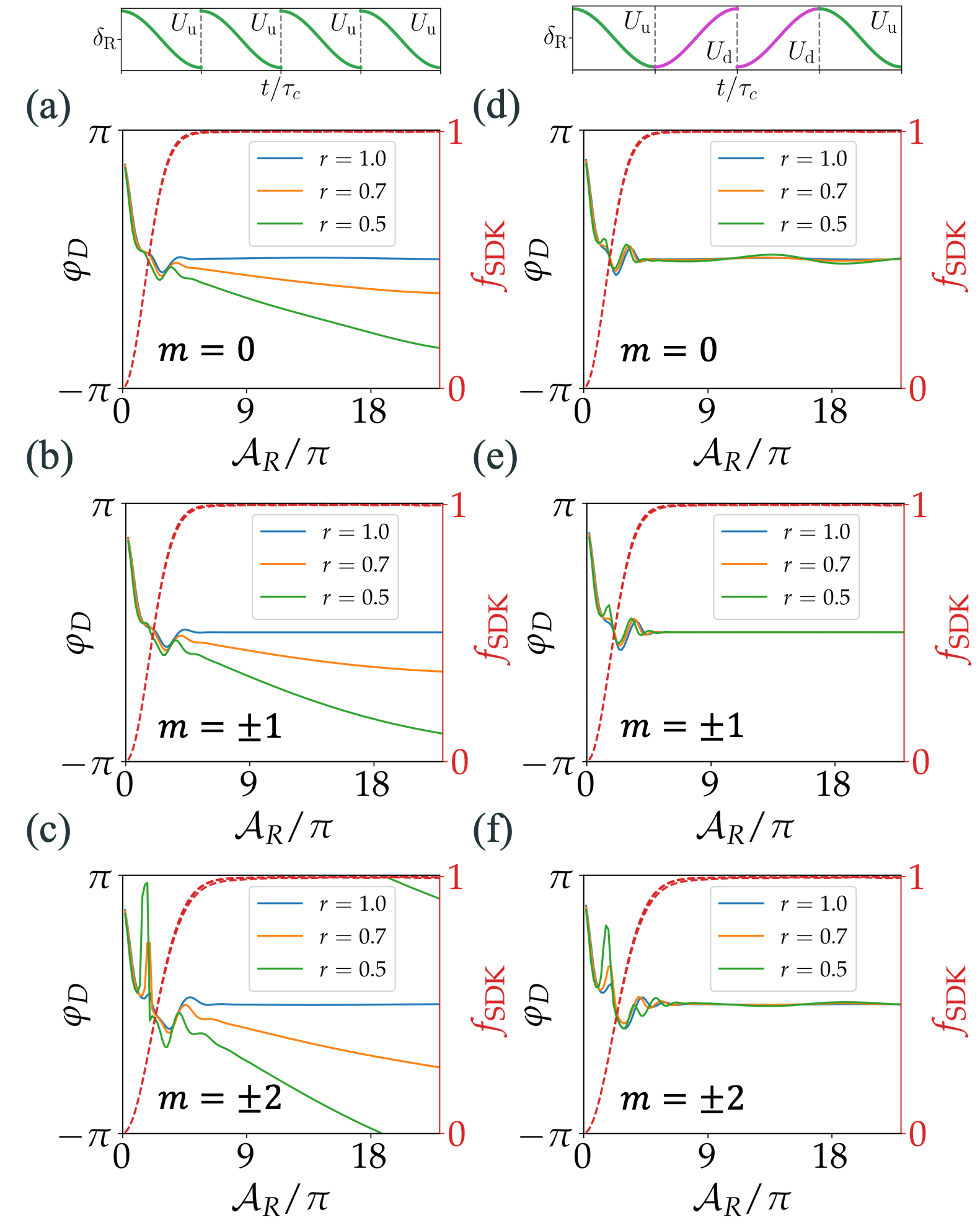
The numerical results in Fig. 7 demonstrate that precise dynamic phase cancellation can be achieved by pairing with into the balanced . In fact, we find that the dynamic phase cancellation in the balanced chirp-alternating scheme is substantially more robust than the traditional double-SDK by Eq. (8), as following.
As in Sec. II.4, the traditional method of dynamic phase cancellation Jaffe et al. 2018 requires perfect swapping for the successive controls. Practically the k-vector swapping is typically accompanied by a modification of intensity ratio. For example, in the retro-reflection setup (Fig. 2(a)), the amplitude of the reflected beam is reduced by a factor due to the imperfect reflection, leading to unbalanced dynamic phases associated with to compromise their cancellation in the traditional double-SDK (Eq. (8)) Kotru et al. 2015; Jaffe et al. 2018. In fact, this systematic exists quite generally in retro-reflection setups since the 2-photon shift is sensitive to the laser intensities ratios Weiss et al. 1994; Gustavson 2000.
In contrast, here we notice that in the sequence (Eq. (11)) the dynamic phase by any pair is expected to be cancelled by a pair later. In the adiabatic limit the cancellation is guaranteed, since for free atom starting from any specific 2-level spin state, the sign of the chirp frequency dictates the adiabatic quantum number Zhu and Wang 2002 and thus the sign of the dynamic phase in the adiabatic limit.
To demonstrate the robust dynamic phase cancellation, in Fig. 8, we compare according to Eq. (9) for the and controls. The values are given in the same plots, with which we see that the high in the quasi-adiabatic regime to be hardly affected even by a poor reflectivity . On the other hand, in contrast to Fig. 8(a-c) (left) where is required for precise suppression of (blue line), in Fig. 8(d-f) (right) the is largely suppressed so long as . It is worth noting that the residual variation of for in Fig. 8(d-f) in the quasi-adiabatic regime are coupled to the coherent spin leakage dynamics (Fig. 6(d-f)). Nevertheless, even for similar to the experimental situation in this work, the residual phase variations are still limited to 50 mrad for the sub-spins, and 3 mrad for the sub-spins, respectively.
IV.5 Area-enhancing atom interferometry
So far in this section, we have shown that matterwave phase gate prescribed by the ideal double-SDK (Eq. (8)) can be faithfully implemented by the balanced chirp-alternating sequence , to coherently shift any , components of hyperfine spinor matterwave with opposite momentum within nanoseconds. For control parameters in this experimental demonstration, our numerical results already suggest fairly high gate fidelity with efficient suppression of the coherent spin leakage and inhomogenuous dynamic phase. In future work, by increasing and ratios and the laser intensities in proportion (Appendix F), the residual imperfections can be further suppressed to meet the exquisite requirements in the applications of quantum information processing García-Ripoll et al. 2003; Duan 2004; Schäfer et al. 2018; Flühmann et al. 2019 and quantum enhanced atom interferometry Szigeti et al. 2020; Wu et al. 2020; Anders et al. 2021; Greve et al. 2021

Here, to demonstrate the utility of the adiabatic SDK sequence for precision measurements, we numerically investigate a simple atom interferometry scheme McGuirk et al. 2000; Kotru et al. 2015; Jaffe et al. 2018 where an “enclosed area” is enhanced by the sequences. As in the Mach-Zehnder configuration in Fig. 9(a), we consider the two spinor matterwave components forming a loop to interfere at (the dashed lines). When sensing a constant force field, the difference of matterwave phase shifts along the two paths, associated with the path-dependent diffraction phase Asenbaum et al. 2020, is read out interferometrically Müller et al. 2009; Bertoldi et al. 2019. Here is the spatial-temporal “area” enclosed by the loop. When the duration of the pulsed rotations are negligibly short relative to the “interrogation time” , then is easily evaluated. Here is the photon recoil velocity. Clearly, when the atomic interferometer acts as a force sensor, its sensitivity increases with . In fact, to achieve as large “area” as possible within a measurement time is of general importance to precision measurements with light pulse atom interferometry Peters et al. 1997; McGuirk et al. 2000; Müller et al. 2009.
More specifically, the enclosed area is defined as during a 3-pulse Raman interferometry sequence by integrating the relative displacement between the two matterwave diffraction paths under the three operations as splitter (), mirror () and combiner (). We generally refer the idealized local spin rotations as for the Raman interferometer, for any spin state within . Here is the local Raman optical phase. Notice the spatial-dependent rotation can in principle be generated by the Eq. (4) Hamiltonian foo b as phase-coherent “half” and “full” kicks. The splitter and mirror operations in the standard light Raman interferometer can then be expressed as , and respectively to manipulate the spin states while imparting the photon recoil momentum.
We now consider enhancing the enclosed area of the standard 3-pulse Raman interferometer with the chirp-alternating SDK sequence. In particular, we consider the Fig. 9(a) scheme with the spinor matterwave diffraction paths marked with solid lines: a is first applied at to increase the momentum displacement between the two interfering paths from by to with the spin-dependent kicks. This -enhancement is followed by an opposite at before the -operation to recover the initial . To ensure that the interfering paths spatially overlap at , an additional pair of opposite momentum boosts, are applied at after the and before the operation respectively. By properly choosing the ratio, spurious interference by imperfect and controls can be suppressed Sidorenkov et al. 2020; Dubetsky and Kasevich 2006. With , the enclosed area of the resulting interfering loop is enhanced to .
For the numerical simulation, we consider at the atomic state to be initialized at certain and subjected to the -enhanced 3-pulse interferometry sequence. The output atomic state, right before the final matterwave combiner , can then be written as , with to be -dependent. Here designates free propagation of matterwave for time . The , takes into account the free propagation of matterwave between the standard and area-enhancing sequences. We numerically evaluate for 1D spinor matterwave between ( is the optical wavelength), as described in Appendix B. To focus on the performance of SDK, we set as perfect pulses and as perfect mirror pulse respectively. A further simplification sets for the idealized controls, with which we numerically evaluate for an initially unpolarized atomic sample. Here are summed over all sub-spins for Pauli matrices with . corresponds to observables of experimental measurements in which Zeeman sublevels are not resolved, as in most atom interferometry experiments with hyperfine state-dependent fluorescence readouts Peters et al. 1997.
With chosen as free 1D propagation, the values of and only affect contributions of spurious interfering paths into the final readouts Sidorenkov et al. 2020; Dubetsky and Kasevich 2006 in the simulation. With set as ideal, the spurious interfering paths are from imperfect diffractions only. Notably, since successive adiabatic SDKs here within each last merely tens of nanoseconds, the spatial displacements among the spurious interfering paths are negligibly small comparing with the typical coherence length of cold atom samples, and therefore do not alter the matterwave dynamics Petitjean et al. 2007; Su et al. 2010. We have randomly sampled the atomic initial position and velocity to numerically verify that the residual spurious interference are indeed suppressible. Practically, to generate the results in Fig. 9(b-d) with all spurious interference removed in an efficient manner, we simply apply a digital filter to remove unwanted diffraction orders after each sequence.
We are particularly interested in the interferometry contrast and diffraction phase offset . The contrast sets the quality of the final matterwave interference fringes. The phase offset , stemming from the unbalanced dynamic phase by the four sequences, enters the interferometry readout as systematic bias against any precision measurements or controls. We evaluate the interferometry contrast as , keeping in mind the ideal rotates by for the final population readouts. The diffraction phase offset is instead evaluated as with to be the relative phase between and right after the ideal splitter. Typical numerical results are presented in Figs. 9(b-d). The simulation is again performed on the 85Rb D1 line, here with spontaneous emission included. For Figs. 9(b-d) on the left panel, the control laser parameters are chosen close to this experimental work, with so both and are quite substantial. Nevertheless, we find four chirp-alternating SDKs can be applied for a 25-fold enhancement of interferometry enclosed area, at a moderate expense of reduced contrast to (which is still highly useful Peters et al. 1997), with to be experimentally calibrated when necessary. Here, to avoid excessive spontaneous emission and coherent leakage (Fig. 6(d-f), the peak needs to be chosen (Fig. 9(b-d)). On the other hand, by doubling the single photon detuning to (with laser intensity increased in proportion to maintain the Raman Rabi frequency), are halved, while the impact of leakage are dramatically suppressed in the sequence (Figs. 9(e-g), also see Appendix F) foo c. The further detuned sequence should thus support up to 50-fold enhancement of interferometry enclosed area, with spontaneous-emission-limited contrast.
V Discussions
Significant aspects of advanced quantum technology today are based on controlling alkaline atoms through their center-of-mass motion and ground-state hyperfine interaction. The two long-lived degrees of freedom can be entangled optically by transferring photon recoil momentum with Raman excitations. The tiny atomic recoil effect can be amplified by the repetitive application of such excitations. The spin-dependent large momentum transfer is expected to improve the scalability for precision measurements in atom interferometry McGuirk et al. 2000; Kotru et al. 2015; Jaffe et al. 2018 and for quantum information processing with trapped ions García-Ripoll et al. 2003; Duan 2004; Mizrahi et al. 2013; Lo et al. 2015; Flühmann et al. 2019. Practically, unlike interrogating microscopically confined single ions where Raman excitation with multiple-THz single-photon detuning is feasible Mizrahi et al. 2014; Ballance et al. 2016, addressing larger samples prefers efficient excitations at moderate single-photon detunings. The seemingly unavoidable imperfections associated with spin-leakages and dynamic phases need to be managed in non-traditional ways, for achieving the high speed, high fidelity control with intensity-error resilience required by the next generation quantum technology Schäfer et al. 2018; Flühmann et al. 2019; Szigeti et al. 2020; Wu et al. 2020; Anders et al. 2021; Greve et al. 2021.
In this work, we have demonstrated a novel configuration of adiabatic SDK implemented on an optical delay line, which is able to reach the speed limit of Raman SDK control Mizrahi et al. 2013; Mizrahi et al. 2014, featuring robust intensity-error resilience, while maintaining various advantages of optical retro-reflection established for precision atom interferometry. The experimental characterization of the technique is limited to the hyperfine population and spin-dependent momentum transfers, but we clarify in Sec. IV that high precision phase gates enabling spin-dependent large momentum transfer can be efficiently realized at the moderate single-photon detuning, by properly programming the chirp direction to suppress the accumulation of coherent errors. We have provided numerical evidence that the chirp-balanced SDK scheme support faithful, parallel control of multi-Zeeman spinor matterwave, with giant spin-dependent forces applied within nanoseconds to rapidly shift the phase-space spin separation, even with the 10 mW laser power as in this work. Since within nanoseconds various low-frequency noises including those due to matterwave dispersion are negligible for cold atoms, we expect accurate implementation of the full scheme to be benchmarked in future interferometric measurements.
Our work suggests that Raman SDK can be dynamically perfected against multi-level couplings and dynamic phase broadening, for error-resilient parallel control of multiple hyperfine spinors within nanoseconds, with exquisite precision. Operating in the unconventional regime of Raman control Weiss et al. 1994; Wineland et al. 2003, the technique requires relatively moderate laser intensity when comparing with similar techniques for controlling microscopically confined ions Mizrahi et al. 2013; Schäfer et al. 2018; Flühmann et al. 2019. Nevertheless, we note the high speed SDK demonstrated in this work is realized by weakly focusing the milli-Watt level output from OAWG He et al. 2020b to a mesoscopic sample to reach the required intensity. Our technique is immediately useful for coherently controlling mesoscopic ultra-cold samples for quantum simulation Gross and Bloch 2017; Blatt and Roos 2012 and atom interferometry Wang et al. 2005; Hughes et al. 2009; Debs et al. 2011; Abend et al. 2016. By improving the peak power of the nanosecond pulses Macrae et al. 2021; Wang et al. 2022; Jayich et al. 2014; Ma et al. 2020; Liu et al. 2022, our method may drastically enhance the practical benefits of large-momentum beamsplitting in Raman atom interferometry McGuirk et al. 2000; Kotru et al. 2015; Jaffe et al. 2018, and to support ultra-precise matterwave control for quantum enhanced technologies Szigeti et al. 2020; Wu et al. 2020; Greve et al. 2021; Anders et al. 2021.
Acknowledgements
We thank Yidi Ma and Xing Huang for experimental assistance. We are grateful to Prof. Yiqiu Ma for insightful comments to the manuscript, and to Prof. Xiaopeng Li and Prof. Haidong Yuan for helpful discussions. We acknowledge support from National Key Research Program of China under Grant No. 2017YFA0304204 and No. 2016YFA0302000, from NSFC under Grant No. 12074083.
Appendix A Full Hamiltonian
The theoretical analysis as well as numerical simulation in this work is based on the full light-atom interaction Hamiltonian on the D1 line. Following the notation in the main text, the effective, non-Hermitian Hamiltonian is written as
| (15) |
Here are decided by the energy of reference level in the excited and ground state manifolds respectively, chosen as the top hyperfine levels in this work. The laser Rabi frequency,
| (16) |
is accordingly written in the frame under the rotating wave approximation. to be the atomic electric dipole operator. The , are the raising and lowering operators between states and . Similar operators are defined for all the other , and state combinations.
The full in Eq. (15) is rewritten as Eq. (4) in the main text. For weak off-resonant pulses and to facilitate understanding of ground-state Raman interaction, we can also adiabatically eliminate the excited states to approximately have
| (17) |
with the convention of summing over repeated indices Cidrim et al. 2021. The single photon detuning is defined as . The vector is the k-vector associated with the Raman transition driven by the counter-propagating pulses.
The Raman coupling associated with in line 2 of Eq. (17) is accompanied by a momentum transfer to the spinor matterwave. Similarly, the “counter-rotating” term in line 3 of Eq. (17) leads to an opposite, momentum transfer. For smooth laser pulses with bandwidth to be discussed, this “counter-rotating” Raman process is energetically suppressed. The regime of resonant Raman interaction with directional momentum transfer is the focus of this work.
Appendix B Numerical model
We numerically simulate the evolution of 1D spinor matterwaves with full D1 light-atom interactions Sievers et al. 2015; Bruce et al. 2017 driven by the counter-propagating Raman pulses as in Fig. 1 and 2. To account for radiation damping, we follow a stochastic wavefunction method Dum et al. 1992 to evaluate the wavefunction for atom at location under the non-Hermitian Hamiltonian (see Eq. (15) with non-Hermitian part in the first line). Here is the natural linewidth of the D1 line. The simulations treat both the internal and external motion of the spinor matterwave quantum mechanically. For the purpose, we sample densely over a uniform grid within and sparsely in the plane, and follow a split-operator method to evaluate internal/external atomic motion numerically with interleaved steps. Taking advantage of the short for single SDK, the internal state dynamics is evaluated within a single step with frozen external motion under a local basis, with atomic position treated as a parameter of . The evaluation of observables later is normalized by , with corrections from stochastic contributions to be discussed shortly. Between SDKs, a Fourier transform along can be performed to evolve the free-flying spinor matterwave along if necessary. To save computation resources, the relatively simple atomic dynamics in the x-y plane is ignored. To evaluate momentum distribution of spinor matterwave, we simply perform a Fourier transform to the space dependent for any specific spin state .
Beyond the coherent evolution, the simulation complexity is substantially reduced by skipping the evaluation of stochastic trajectories heralded by a single “quantum jump” Dalibard et al. 1992; Carmichael 1993. Specifically, after each pulsed interaction, the trajectories suffering a quantum jump are simply assumed to repopulate in a uniform manner with properly shifted photon recoil momentum. Without further evolution, these trajectories contribute to the evaluation of incoherent, single-time observables such as hyperfine population and photon momentum transfer. The overall probability of spontaneous emission is determined by the norm of the final wavefunction, , after a total evolution time . The simplification is generally justified for evaluating coherent observables of interest, since the expectation values shifted stochastically lead to zero coherent contributions. For the incoherent observables such as average photon momentum and hyperfine population, the simplification is supported by the simple D1 structure under consideration here Sievers et al. 2015, where a single spontaneous emission effectively randomizes the following Raman interaction dynamics.
Appendix C A Markovian model for estimation
For atoms subjected to multiple SDKs, the dynamics of spinor matterwave that deviates from the ideal control can be depicted as diffusing in a “momentum-lattice” He et al. 2020a. Our numerical simulation suggests that with fair efficiency of single adiabatic pulse to achieve hyperfine transfer efficiency of , the resulting average momentum and population roughly follow a simple Markovian model. The model assumes that both the momentum and population transfer by the next kick are decided by the present population difference only. The details of the Markovian model are described as following.
Suppose that after kicks, the atomic ensemble is with momentum (in unit of ) and population contrast , then the next kick will impart momentum as
| (18) |
where is the hyperfine population transfer efficiency in absence of the spontaneous emission. Here we have assumed that during the single pulse process, the spontaneous emission occurs with a uniform distribution of probability, thus the associated population recycled to the ground states acquires half of momentum on average.
Similarly, the population distribution can be written as
| (19) |
so that
| (20) |
We define Raman transfer efficiency as . When both and are close to unity, Eqs. (18)(20) can be approximated as
| (21) |
With the recursion relations by Eq. (21), we arrive at
| (22) |
Finally, we remark that for the Raman SDK, there is a slight difference of spontaneous emission loss for single kicks between the and process. As we consider repetitive SDK with up to a quite large number (e.g. in our experiment), we effectively set the same parameter for the opposite population transfer processes.
Appendix D Absorption imaging analysis
In Sec. III we have introduced the double imaging technique. This section provides details on deriving recoil momentum and population transfer from the imaging data.
Our atomic sample is prepared in a cross-dipole trap with slight asymmetry. When deriving the momentum transfer from the double images as in Fig. 3, we found that neither before nor after the time-of-flight, the absorption profile can fit perfectly to a 2D Gaussian. In addition, due to the relatively short exposure time of 20s to the weak probe (), there is substantial photon shot noise in single-shot images. To faithfully retrieve central position and atom number from each pair of double-image, we take the following procedure. First, we repeat the same type of measurements for shots, and do a principal components analysis to all pairs of double-images after background subtractions. The first three components are kept for the following analysis. We then do a 2D Gaussian fit, expanding the fitted Gaussian profiles to times the waist into a wide enough step-wise mask. The population ratios are evaluated by the ratio of total counts between the two images within the mask, where the center-of-mass (COM) positions and are also directly evaluated.
We note that the first image senses atoms at “” states only. In other words, the atoms kicked to the “visible” (or “invisible”, depending on whether the kicking number is an even or odd number) hyperfine levels are post-selected. Since there is a small interval between SDK and the first image, there is a bias to the COM position of the whole cloud due to this post-selection. To correct for the bias, we rewrite the position difference as . Here and are the mean velocity for the whole atomic ensemble and for the atoms in after SDKs, respectively. The correction to the post-selection induced velocity bias is then given by
| (23) |
Here, depends on the relation between and . The relation can be approximated with the model in Appendix C. With in our experiment, this correction is typically (the signs depend on ), which impacts at level. The correction is model-dependent. We correct for the bias in our final estimation of and leave as the dominant uncertainty in our estimation.
Appendix E Impact of mirror optical loss to

Numerical simulations suggest that the reflectivity of the retro-reflection mirror (Fig. 2) affects at the -level. To investigate the effect, we sample during the simulation, and calculate Raman transfer efficiency and SDK fidelity with peak Raman pulse area as in Fig. A1(a). In light of the mixed state nature of the experimental measurements, here the results are again averaged over the initial states . For all the simulation, we evaluate peak Rabi frequency as in previous work of electric dipole transition control He et al. 2020a where the laser beam waist and the atomic ensemble size are also carefully characterized. Based on the geometry parameters, we plot the fractions of atoms as a function of peak Raman pulse area in Fig. A1(a) in histograms. The fractions are applied to weight the average over all pulse areas for the evaluation of and at various reflectivity in Fig. A1(b). On the plot, the measured Raman transfer efficiency suggest . This reflectivity is consistent with experimental measurements on the ratio of Stark shifts by the incident and reflected beams.
Appendix F Different nuclear spins
In the main text we have discussed the nanosecond SDK for 85Rb atoms featuring weakly-coupled sub-spins (Fig. 1). In particular, in Sec. IV we have shown that within the experimentally explored parameter regime, a balanced chirp-alternating sequence (Eq. (11)) quite efficiently suppress the leakage among the five sub-spins to achieve phase gate fidelity at large , for most of light intensities (Fig. 7). As clarified in Sec. IV.3, the leakage suppression exploits the approximate time-reversal symmetry to cancel the non-adiabatic tunnelings among the sub-spins. Practically, the leakage dynamics supported by the non-degenerate sub-spins is complex enough to merit future study by itself. Instead of attempting a full understanding of the dynamics, in this section we provide numerical examples of coherent matterwave control for other alkaline species. The simulations are according to those outlined in Appendix B and in parallel to Fig. 7, in particular with spontaneous emission ignored by setting on the D1 line. The examples with nuclear spin are given in Fig. A2, Fig. A3, Fig. A4 respectively. To compare with the Fig. 7 results, we set the hyperfine splittings , to be identical to 85Rb for all the simulations. In addition, we choose , twice as those for Fig. 7, to demonstrate the substantially enhanced spin-leakage suppression.

Figure A2 compares the SDK phase gate fidelity by the traditional (left) and the chirp-alternating (right) sequences, for the 87Rb-like atom. With for (Fig. 1(a)), there are three sub-spins with . The sub-spin is only coupled to single states with (similar to the end-couplings in Fig. 1(a)). The gate infidelity for is slightly compromised by the resulting leakage ( between and at ), as in Fig. A2(a). For comparison, in absence sub-spin leakage to fix, the gate fidelity for the chirp-alternating in Fig. A2(d) is even slightly worse (between and at ). Nevertheless, we note the is still preferred practically, not only because it supports the sub-spin performance to be discussed next, but also due to the robust dynamic phase cancellation (Sec. IV.4).
In contrast, the resonant leakages between the degenerate sub-spins is substantial which strongly affect the gate fidelity for . This is shown in Fig. A2(b) similar to the Fig. 7(b) results. Interestingly, in absence of the end-couplings for 85Rb (Fig. 1(a)), here the leakage-suppression by chirp-alternating the sequence is essentially perfect for the 87Rb-like atom. As in Fig. A2(e), the reaches level at large , which appears to be only limited by the SU(2) non-adiabaticity of single adiabatic SDK Guery-Odelin et al. 2019, as suggested by in Fig. A2(c,f) evaluated according to Eq. (6), after setting to remove the -changing couplings (Eq. (1)).

Next, Figure A3 investigates SDK phase gate fidelity for 85Rb featuring five nearly degenerate sub-spins with , as in the main text. Here the single-photon detuning is doubled to be compared with the Fig. 7 results. We see that for both and sequences, at the larger the intensity-dependent oscillatory features due to the spin-leakages are slowed (with respect to the increasing ) and sharpened. With the couplings halved (Eq. (1)) relative to the Fig. 7 case, the infidelity for the sequence is now below at the large , for most of large laser intensities. The low- region are now narrowed within .

Finally, Figure A4 investigates SDK phase gate fidelity for 133Cs-like atom featuring seven nearly degenerate sub-spins with . With the large number of sub-spins involved, the spin-leakage dynamics are more complex. Nevertheless, comparing with the gate fidelity for in Figs. A4(a-d), in Figs. A4(e-h) the drastic fidelity enhancement due to the spin-leakage suppression by is evident. For the seven sub-spin system, the strips of low intensity region become quite widely distributed. Consequently, comparing to the 87Rb-like atom with Fig. A2(d)(e) and the 85Rb-like atom with Fig. A3(d-f), it becomes more difficult to find a suitable range of laser intensities for the high-fidelity multi- SDK phase gates to operate. More generally, as the nuclear spin increases, it becomes more difficult to achieve independent phase gate prescribed by Eq. (8) in the main text with composite SDK. To improve the aspect, variations of additional pulse parameters beyond the simple chirp-alternation as in this work may be explored. In addition, in measurements where coherent control of a single spinor matterwave, such as the clock states, is all that is needed, then circularly polarized nanosecond pulses can be applied to naturally suppress the -changing transitions during the spinor matterwave control foo a. To this end, we expect the delay-line based nanosecond SDK to fascilitate the accurate implementation of preserving Raman control with circularly polarized pulses Gustavson 2000.
References
- Kasevich and Chu (1991) M. Kasevich and S. Chu, Physical Review Letters 67, 181 (1991).
- Featonby et al. (1996) P. D. Featonby, G. S. Summy, J. L. Martin, H. Wu, K. P. Zetie, C. J. Foot, and K. Burnett, Physical Review A 53, 373 (1996).
- McGuirk et al. (2000) J. M. McGuirk, M. J. Snadden, and M. A. Kasevich, Physical Review Letters 85, 4498 (2000).
- Metcalf and van der Straten (1999) H. J. Metcalf and P. van der Straten, Laser Cooling and Trapping( Springer-Verlag) (1999).
- Mizrahi et al. (2013) J. Mizrahi, C. Senko, B. Neyenhuis, K. G. Johnson, W. C. Campbell, C. W. S. Conover, and C. Monroe, Physical Review Letters 110, 203001 (2013).
- Jaffe et al. (2018) M. Jaffe, V. Xu, P. Haslinger, H. Müller, and P. Hamilton, Physical Review Letters 121, 040402 (2018), 1803.09024 .
- Harty et al. (2014) T. P. Harty, D. T. C. Allcock, C. J. Ballance, L. Guidoni, H. A. Janacek, N. M. Linke, D. N. Stacey, and D. M. Lucas, Phys. Rev. Lett. 113, 220501 (2014).
- Ballance et al. (2016) C. J. Ballance, T. P. Harty, N. M. Linke, M. A. Sepiol, and D. M. Lucas, Phys. Rev. Lett. 117, 060504 (2016).
- Wang et al. (2016) Y. Wang, A. Kumar, T.-Y. Wu, and D. S. Weiss, Science 352, 1562 (2016), 1601.03639 .
- Kotru et al. (2015) K. Kotru, D. L. Butts, J. M. Kinast, and R. E. Stoner, Phys. Rev. Lett. 115, 103001 (2015).
- García-Ripoll et al. (2003) J. J. García-Ripoll, P. Zoller, and J. I. Cirac, Phys. Rev. Lett. 91, 157901 (2003).
- Duan (2004) L. M. Duan, Phys. Rev. Lett. 93, 100502 (2004), arXiv:0401185 [quant-ph] .
- Lo et al. (2015) H. Y. Lo, D. Kienzler, L. De Clercq, M. Marinelli, V. Negnevitsky, B. C. Keitch, and J. P. Home, Nature 521, 336 (2015), arXiv:1412.7100 .
- Ma et al. (2020) Y. Ma, X. Huang, X. Wang, L. Ji, Y. He, L. Qiu, J. Zhao, Y. Wang, and S. Wu, Opt. Express 28, 17171 (2020), arXiv:2004.05320 .
- He et al. (2020a) Y. He, L. Ji, Y. Wang, L. Qiu, J. Zhao, Y. Ma, X. Huang, S. Wu, and D. E. Chang, Phys. Rev. Res. 2, 043418 (2020a), arXiv:2010.16066 .
- Schäfer et al. (2018) V. M. Schäfer, C. J. Ballance, K. Thirumalai, L. J. Stephenson, T. G. Ballance, A. M. Steane, and D. M. Lucas, Nature 555, 75 (2018), arXiv:1709.06952 .
- Flühmann et al. (2019) C. Flühmann, T. L. Nguyen, M. Marinelli, V. Negnevitsky, K. Mehta, and J. P. Home, Nature 566, 513 (2019), arXiv:1807.01033 .
- Szigeti et al. (2020) S. S. Szigeti, S. P. Nolan, J. D. Close, and S. A. Haine, Phys. Rev. Lett. 125, 100402 (2020), arXiv:2005.00368 .
- Wu et al. (2020) Y. Wu, R. Krishnakumar, J. Martínez-Rincón, B. K. Malia, O. Hosten, and M. A. Kasevich, Physical Review A 102, 012224 (2020), 1912.08334 .
- Anders et al. (2021) F. Anders, A. Idel, P. Feldmann, D. Bondarenko, S. Loriani, K. Lange, J. Peise, M. Gersemann, B. Meyer-Hoppe, S. Abend, N. Gaaloul, C. Schubert, D. Schlippert, L. Santos, E. Rasel, and C. Klempt, Phys. Rev. Lett. 127, 140402 (2021), arXiv:2010.15796 .
- Greve et al. (2021) G. P. Greve, C. Luo, B. Wu, and J. K. Thompson, arXiv (2021), 2110.14027 .
- Genov et al. (2014) G. T. Genov, D. Schraft, T. Halfmann, and N. V. Vitanov, physical review letter 113, 043001 (2014).
- Low et al. (2016) G. H. Low, T. J. Yoder, and I. L. Chuang, Physical Review X 6, 041067 (2016), arXiv:1603.03996 .
- Saywell et al. (2018) J. C. Saywell, I. Kuprov, D. Goodwin, M. Carey, and T. Freegarde, Phys. Rev. A 98, 023620 (2018), arXiv:1804.04625 .
- Weiss et al. (1994) D. S. Weiss, B. C. Young, and S. Chu, Applied Physics B 59, 217 (1994).
- Happer (1972) W. Happer, Rev. Mod. Phys. 44, 169 (1972).
- Kasevich and Chu (1992) M. Kasevich and S. Chu, Appl. Phys. B 54, 321 (1992).
- Durfee et al. (2006) D. S. Durfee, Y. K. Shaham, and M. A. Kasevich, Phys. Rev. Lett. 97, 240801 (2006), arXiv:0510215 [quant-ph] .
- Canuel et al. (2006) B. Canuel, F. Leduc, D. Holleville, A. Gauguet, J. Fils, A. Virdis, A. Clairon, N. Dimarcq, C. J. Bordé, A. Landragin, and P. Bouyer, Phys. Rev. Lett. 97, 010402 (2006), arXiv:0604061 [physics] .
- Malossi et al. (2009) N. Malossi, Q. Bodart, S. Merlet, A. Landragin, F. P. D. Santos, and O. D. Paris, Phys. Rev. A 81, 013617 (2009), arXiv:arXiv:0909.0102v2 .
- Zhou et al. (2015a) L. Zhou, S. Long, B. Tang, X. Chen, F. Gao, W. Peng, W. Duan, J. Zhong, Z. Xiong, J. Wang, Y. Zhang, and M. Zhan, Phys. Rev. Lett. 115, 013004 (2015a), arXiv:1503.00401 .
- Perrin et al. (2019) I. Perrin, J. Bernard, Y. Bidel, A. Bonnin, N. Zahzam, C. Blanchard, A. Bresson, and M. Cadoret, Phys. Rev. A 100, 053618 (2019), arXiv:1907.04403 .
- Hartmann et al. (2020) S. Hartmann, J. Jenewein, E. Giese, S. Abend, A. Roura, E. M. Rasel, and W. P. Schleich, Phys. Rev. A 101, 53610 (2020), arXiv:1911.12169 .
- Peters et al. (1997) A. Peters, K. Y. Chung, B. Young, J. Hensley, and S. Chu, Phil. Trans. R. Soc. Lond. A 355, 2223 (1997).
- Kral et al. (2007) P. Kral, I. Thanopulos, and M. Shapiro, Rev. Mod. Phys. 79, 53 (2007).
- He et al. (2020b) Y. He, L. Ji, Y. Wang, L. Qiu, J. Zhao, Y. Ma, X. Huang, S. Wu, and D. E. Chang, Phys. Rev. Lett. 125, 213602 (2020b).
- Estey et al. (2015) B. Estey, C. Yu, and H. Müller, Phys. Rev. Lett. 115, 083002 (2015).
- Kristensen et al. (2021) S. L. Kristensen, M. Jaffe, V. Xu, C. D. Panda, and H. Müller, Phys. Rev. A 103, 023715 (2021), arXiv:2011.02946 .
- Mizrahi et al. (2014) J. Mizrahi, B. Neyenhuis, K. G. Johnson, W. C. Campbell, C. Senko, D. Hayes, and C. Monroe, Appl. Phys. B 114, 45 (2014).
- Stack et al. (2011) D. Stack, J. Elgin, P. M. Anisimov, and H. Metcalf, Phys. Rev. A 013420, 013420 (2011).
- Wineland et al. (2003) D. J. Wineland, M. Barrett, J. Britton, J. Chiaverini, B. DeMarco, W. M. Itano, B. Jelenkovic, C. Langer, D. Leibfried, V. Meyer, T. Rosenband, and T. Schatz, Phil. Trans. R. Soc. Lond. A 361, 1349 (2003).
- Plotkin-Swing et al. (2018) B. Plotkin-Swing, D. Gochnauer, K. E. McAlpine, E. S. Cooper, A. O. Jamison, and S. Gupta, Phys. Rev. Lett. 121, 133201 (2018), arXiv:1712.06738 .
- Asenbaum et al. (2020) P. Asenbaum, C. Overstreet, M. Kim, J. Curti, and M. A. Kasevich, Phys. Rev. Lett. 125, 191101 (2020), arXiv:2005.11624 .
- Müller et al. (2009) H. Müller, S. W. Chiow, S. Herrmann, and S. Chu, Phys. Rev. Lett. 102, 240403 (2009), arXiv:0903.4192 .
- Gebbe et al. (2021) M. Gebbe, J. N. Siemß, M. Gersemann, H. Müntinga, S. Herrmann, C. Lämmerzahl, H. Ahlers, N. Gaaloul, C. Schubert, K. Hammerer, S. Abend, and E. M. Rasel, Nat. Commun. 12, 1544 (2021), arXiv:1907.08416 .
- Rudolph et al. (2020) J. Rudolph, T. Wilkason, M. Nantel, H. Swan, C. M. Holland, Y. Jiang, B. E. Garber, S. P. Carman, and J. M. Hogan, Phys. Rev. Lett. 124, 83604 (2020), arXiv:1910.05459 .
- Wilkason et al. (2022) T. Wilkason, M. Nantel, J. Rudolph, Y. Jiang, B. E. Garber, H. Swan, S. P. Carman, M. Abe, and J. M. Hogan, arXiv:2205.06965 (2022).
- Zhou et al. (2015b) L. Zhou, S. Long, B. Tang, X. Chen, F. Gao, W. Peng, W. Duan, J. Zhong, Z. Xiong, J. Wang, Y. Zhang, and M. Zhan, Physical Review Letters 115, 013004 (2015b), 1503.00401 .
- Steck (2016) D. A. Steck (2016), available online at http://steck.us/teaching (revision 0.11.5, 27 November 2016).
- Dunning et al. (2014) A. Dunning, R. Gregory, J. Bateman, N. Cooper, M. Himsworth, J. A. Jones, and T. Freegarde, Physical Review A 90, 033608 (2014), 1406.2916 .
- Cidrim et al. (2021) A. Cidrim, A. P. Orioli, C. Sanner, R. B. Hutson, J. Ye, R. Bachelard, and A. M. Rey, Physical Review Letters 127, 013401 (2021).
- Delhuille et al. (2003) R. Delhuille, A. Miffre, C. Robilliard, J. Vigue, M. Bu, and C. Champenois, Phys. Rev. A 68, 013607 (2003).
- Magesan et al. (2012) E. Magesan, J. M. Gambetta, and J. Emerson, Physical Review A - Atomic, Molecular, and Optical Physics 85, 042311 (2012), arXiv:1109.6887 .
- Dalibard et al. (1992) J. Dalibard, Y. Castin, and K. Molmer, Phys. Rev. Lett. 68, 580 (1992).
- Carmichael (1993) H. J. Carmichael, Lecture Notes in Physics, New Series m: Monographs Vol. m18, Springer, Berlin (1993).
- Bergmann et al. (1998) K. Bergmann, H. Theuer, and B. W. Shore, Rev. Mod. Phys. 70, 1003 (1998).
- Vitanov et al. (2001) N. V. Vitanov, T. Halfmann, B. W. Shore, and K. Bergmann, Annual Review of Physical Chemistry 52, 763 (2001).
- Miao et al. (2007) X. Miao, E. Wertz, M. G. Cohen, and H. Metcalf, Physical Review Letters 75, 011402 (2007).
- Guery-Odelin et al. (2019) D. Guery-Odelin, A. Ruschhaupt, A. Kiely, E. Torrontegui, S. Martínez-Garaot, and J. G. Muga, Rev. Mod. Phys. 91, 045001 (2019), arXiv:1904.08448 .
- Berry (1984) M. V. Berry, Proceedings of the Royal Society of London. A. Mathematical and Physical Sciences 392, 45 (1984).
- Zhu and Wang (2002) S.-l. Zhu and Z. D. Wang, Phys. Rev. Lett. 89, 097902 (2002).
- Gustavson (2000) T. L. Gustavson, Ph.D. thesis, Standford University (2000).
- Lu et al. (2005) T. Lu, X. Miao, and H. Metcalf, Phys. Rev. A 71, 061405 (2005).
- Sievers et al. (2015) F. Sievers, N. Kretzschmar, D. Fernandes, D. Suchet, M. Rabinovic, S. Wu, C. Parker, L. Khaykovich, C. Salomon, and F. Chevy, Physical Review A - Atomic, Molecular, and Optical Physics 91, 023426 (2015).
- Genov and Vitanov (2013) G. T. Genov and N. V. Vitanov, Phys. Rev. Lett. 110, 133002 (2013).
- Kang et al. (2018) Y. H. Kang, Y. H. Chen, Z. C. Shi, B. H. Huang, J. Song, and Y. Xia, Phys. Rev. A 97, 033407 (2018).
- Jo et al. (2019) H. Jo, Y. Song, and J. Ahn, Opt. Express 27, 3944 (2019).
- Shore (2014) B. W. Shore, J. Mod. Opt. 61, 787 (2014).
- Muniz et al. (2018) J. A. Muniz, M. A. Norcia, J. R. K. Cline, and J. K. Thompson, arXiv:1806.00838 (2018).
- foo (a) It is worth pointing out that the spin leakage is naturally suppressed when Raman transitions are driven by beams with a same circular polarization Gustavson 2000. Here, circularly polarized nanosecond SDK can be implemented on a compact delay line. When combined with the balanced chirp-alternating scheme, coherent control of a specific Zeeman spinor matterwave component can be achieved with robustly cancelled dynamic phases. However, since both the 2-photon shift and the Raman Rabi frquency of the circular polarized SDK are highly dependent, it would be more difficult to achieve the parallel multi-Zeeman spinor control.
- Bertoldi et al. (2019) A. Bertoldi, F. Minardi, and M. Prevedelli, Phys. Rev. A 99, 033619 (2019), arXiv:1812.11890 .
- foo (b) In atom interferometry, the operations are usually achieved with simple Raman pulses with little resiliance to control errors. Methods for error-resliance realization of are discussed in e.g. ref. Saywell et al. 2018. Similarly, we find can be achieved with composite pulses. The results will be presented in a future publication.
- Sidorenkov et al. (2020) L. A. Sidorenkov, R. Gautier, M. Altorio, R. Geiger, and A. Landragin, Phys. Rev. Lett. 125, 213201 (2020), arXiv:2006.08371 .
- Dubetsky and Kasevich (2006) B. Dubetsky and M. A. Kasevich, Phys. Rev. A - At. Mol. Opt. Phys. 74, 023615 (2006), arXiv:0604082 [physics] .
- Petitjean et al. (2007) C. Petitjean, D. V. Bevilaqua, E. J. Heller, and P. Jacquod, Phys. Rev. Lett. 98, 164101 (2007).
- Su et al. (2010) E. Su, S. Wu, and M. Prentiss, Phys. Rev. A - At. Mol. Opt. Phys. 81, 043631 (2010).
- foo (c) The projected interferometry performance is subtly enhanced by the time-reversal symmetry of the interferometry itself, introduced by the rotation. Practically, the symmetry can be broken by atomic motion during the long interrogation time . In this case, the high-level performance can still be retained by avoding the narrow low- intensity regions in all the SDK sequences.
- Gross and Bloch (2017) C. Gross and I. Bloch, Science 357, 995 (2017).
- Blatt and Roos (2012) R. Blatt and C. F. Roos, Nat. Phys. 8, 277 (2012).
- Wang et al. (2005) Y.-J. Wang, D. Anderson, V. Bright, E. Cornell, Q. Diot, T. Kishimoto, M. Prentiss, R. Saravanan, S. Segal, and S. Wu, Phys. Rev. Lett. 94, 090405 (2005).
- Hughes et al. (2009) K. J. Hughes, J. H. Burke, and C. A. Sackett, Phys. Rev. Lett. 102, 150403 (2009).
- Debs et al. (2011) J. E. Debs, P. A. Altin, T. H. Barter, D. Döring, G. R. Dennis, G. McDonald, R. P. Anderson, J. D. Close, and N. P. Robins, Phys. Rev. A - At. Mol. Opt. Phys. 84, 033610 (2011), arXiv:1011.5804 .
- Abend et al. (2016) S. Abend, M. Gebbe, M. Gersemann, H. Ahlers, H. Müntinga, E. Giese, N. Gaaloul, C. Schubert, C. Lämmerzahl, W. Ertmer, W. P. Schleich, and E. M. Rasel, Phys. Rev. Lett. 117, 203003 (2016).
- Macrae et al. (2021) C. D. Macrae, K. Bongs, and M. Holynski, Optics letters 46, 1257 (2021).
- Wang et al. (2022) Y. Wang, Y. He, L. Ji, J. Hu, X. Huang, Y. Ma, L. Qiu, K. Zhao, and S. Wu, Chinese Opt. Lett. 20, 22 (2022), arXiv:2203.02915 .
- Jayich et al. (2014) A. M. Jayich, A. C. Vutha, M. T. Hummon, J. V. Porto, and W. C. Campbell, Phys. Rev. A 89, 023425 (2014), arXiv:arXiv:1312.4499v1 .
- Liu et al. (2022) R. Liu, Y. Ma, L. Ji, L. Qiu, M. Ji, Z. Tao, and S. Wu, Opt. Express 30, 27780 (2022), arXiv:2110.15537 .
- Bruce et al. (2017) G. D. Bruce, E. Haller, B. Peaudecerf, D. A. Cotta, M. Andia, S. Wu, M. Y. H. Johnson, B. W. Lovett, and S. Kuhr, J. Phys. B: At. Mol. Opt. Phys 50, 095002 (2017).
- Dum et al. (1992) R. Dum, A. S. Parkins, P. Zoller, and C. W. Gardiner, Phyiscal Rev. A 46, 4382 (1992).