Scaling Up Knowledge Graph Creation to Large and Heterogeneous Data Sources
Abstract
RDF knowledge graphs (KG) are powerful data structures to represent factual statements created from heterogeneous data sources. KG creation is laborious and demands data management techniques to be executed efficiently. This paper tackles the problem of the automatic generation of KG creation processes declaratively specified; it proposes techniques for planning and transforming heterogeneous data into RDF triples following mapping assertions specified in the RDF Mapping Language (RML). Given a set of mapping assertions, the planner provides an optimized execution plan by partitioning and scheduling the execution of the assertions. First, the planner assesses an optimized number of partitions considering the number of data sources, type of mapping assertions, and the associations between different assertions. After providing a list of partitions and assertions that belong to each partition, the planner determines their execution order. A greedy algorithm is implemented to generate the partitions’ bushy tree execution plan. Bushy tree plans are translated into operating system commands that guide the execution of the partitions of the mapping assertions in the order indicated by the bushy tree. The proposed optimization approach is evaluated over state-of-the-art RML-compliant engines, and existing benchmarks of data sources and RML triples maps. Our experimental results suggest that the performance of the studied engines can be considerably improved, particularly in a complex setting with numerous triples maps and large data sources. As a result, engines that time out in complex cases are enabled to produce at least a portion of the KG applying the planner.
Keywords:
Knowledge graph creation, Data Integration Systems, RDF Mapping Languages, Query Execution Planning1 Introduction
Knowledge graphs (KGs) are data structures able to converge data and metadata collected from various data sources [34]. Data sources can be heterogeneous and comprise structured, semi-structured, or unstructured data. Nevertheless, several parameters like number and type of mapping assertions and data source complexities like large volume, heterogeneity, and high duplicate rates may considerably affect the performance of KG creation.
The declarative definition of KGs using W3C standard languages like R2RML [27] and RML [32] have gained momentum, and numerous real-world applications (e.g., [17, 39, 46]) resort to these formalisms to provide transparent, maintainable, and traceable processes of KG creation. As a result, the scientific community has actively contributed to the problem of KG creation with formal systems to formalize the whole process [44, 51, 52], theoretical and empirical analyses of parameters that affect the process performance [21, 48], engines for KG creation [23, 31, 35, 58], and benchmarks to assess the engines’ performance [22]. Despite these recent advances, existing engines could still struggle to perform well in real-world settings. For example, KG creation in biomedicine demands the integration of various data types [56], e.g., genes, drugs, scientific publications, and clinical records, which change frequently. Complex pipelines composed of numerous mapping rules (e.g., more than 1,000 rules) collecting data from sources in a myriad of formats (e.g., relational or textual) may be costly in terms of time and memory consumption.
Our work is inspired by our experience in developing such complex pipelines in the context of the EU funded projects iASiS [2], BigMedilytics [1], and CLARIFY [3], as well as in CoyPu [4], a German project funded by the Federal Ministry of Economics and Climate Protection [5]. Specifically, the SDM-Genomic benchmark [10, 11] is inspired by the computational challenges addressed during the integration of genomic data from the COSMIC database [14] into the KGs of the biomedical projects. These mapping assertions are complex regarding dataset size, the number of mapping assertions, and types of joins among them. Initially, none of the existing engines (e.g., RMLMapper [30], RocketRML [58], and SDM-RDFizer [35]) was able to run the complex mapping assertions on the project data in a reasonable time (e.g., less than 48 hours). Since biomedical data change frequently, these mappings are executed periodically. Manually, knowledge engineers rewrote the mapping assertions [6] and transformed them into simpler rules executable by the SDM-RDFizer. These transformations inspired the proposed optimization techniques for mapping assertions.
Problem Statement and Objectives. We tackle the problem of efficiently executing KG creation when the process is declaratively defined using mapping languages like R2RML or RML (a.k.a. [R2]RML). We formalize the problem as an optimization problem, where mapping assertions are grouped and scheduled into execution plans that reduce execution time or memory consumption. A solution to the problem is an execution plan of groups of mapping assertions scheduled as a binary bushy tree [53]; this execution avoids the sequential execution of the mapping assertions and reduces the complexity of duplicate removal. The problem of generating such execution plans is known to be NP-hard [53] in general. Thus, our objective is to efficiently traverse the space of execution plans and generate a plan that scales up to complex scenarios.
Our Proposed Solution. We propose a heuristic-based approach that groups mapping assertions executed against at most two data sources. The execution of the identified groups of mapping assertions is scheduled in a bushy tree, where duplicate removal is executed as soon as possible, i.e., they are pushed down into the tree and executed following an eager evaluation approach. We present two greedy approaches; one algorithm partitions the mapping assertions into groups, while the other generates bushy trees that schedule the groups’ execution. The approach is engine agnostic, i.e., the execution plan can be executed in any of the existing KG creation engines to speed up the KG creation process. Empirically, we study the performance of the proposed approach and the generated plans. The study assesses the performance of state-of-the-art RML engines on existing benchmarks of KG creation. The observed outcomes put in perspective the benefits of scheduling the execution of mapping assertions following the generated plans. Moreover, these results indicate that not only can the process of KG creation be accelerated, but also consumed memory is reduced. Contributions. In summary, the scientific contributions of this work are as follows:
- •
Engine-Agnostic Execution Planning Techniques for Knowledge Graph Creation. We formalize the KG creation process and present greedy algorithms to generate execution plans that enable the efficient execution of KG creation pipelines. The proposed execution planning techniques implement a two-fold approach. First, mapping assertions are partitioned to avoid more than one join between two different mapping assertions executed in one group. Then, groups of mapping assertions are combined greedily to ensure those that generate instances of the same overlapped predicates are placed lower in the tree to be executed as soon as possible.
- •
Execution Methods for Knowledge Graph Creation. We propose engine-agnostic techniques for the execution of mapping assertions. They translate a bushy tree plan into operating system commands to execute mapping assertions following the order indicated in the bushy tree plan. In case of duplicated RDF triples generated by the execution of groups of assertions, duplicate removal operators are scheduled and executed as soon as possible. This strategy reduces execution time and memory consumption and enables continuous generation of RDF triples.

Figure 1: Mapping Assertions. Mapping assertions are expressed in R2RML –the W3C recommendation standard– and its extension RML. The example comprises a) three concept mapping assertions defining the classes C1, C2, and C3; b) two attribute mapping assertions for the definition of attributeX and attributeY, and c) two role mapping assertions: one referencing assertions defined over the same logical source (i.e., referenced-source), and the other one, referencing assertions defined over different sources (i.e., multi-source). - •
Experimental Assessment of the Proposed Methods. We report on the empirical evaluation of the proposed methods in two benchmarks, SDM-Genomic-Datasets [10] and the GTFS-Madrid-Bench [22], and four [R2]RML-compliant engines: RMLMapper [32], RocketRML [58], Morph-KGC [16], and SDM-RDFizer [35]. In total, 236 testbeds are executed and analyzed. These results suggest savings in execution time of up to 76.09%. Moreover, the proposed execution planning techniques enable the incremental generation of RDF triples. Thus, engines like RMLMapper which times out after five hours with zero produced RDF triples in complex testbeds can generate 32.65% of the total number of RDF triples using planning.
This paper is organized into six additional sections. Preliminaries and a motivating example are presented in section 2, and related approaches are discussed in section 3. Section 4 presents the problem of KG creation and discusses the proposed execution planning techniques. The KG creation techniques implemented to execute bushy tree plans are explained in section 5. Section 6 reports on the results of the empirical evaluation. Lastly, section 7 summarizes lessons learned and outlines future directions.
2 Preliminaries and Motivation
KGs are data structures that model factual statements as entities and their relationships using a graph data model [34]. The creation process of a KG is defined in terms of a data integration system where is a set of classes and properties of a unified ontology, is a set of data sources, and corresponds to mapping rules or assertions defining concepts in as conjunctive queries over sources in . The execution of the rules over data from sources in generates the instances of . Figure 1 shows mapping assertions represented in RML [32], an extension of R2RML [8], the W3C recommendation for mapping rules from data sources in various formats (e.g., CSV and JSON) to RDF.
Mapping Assertions. Mapping rules in are formalized as Horn clauses
that follow the Global As View (GAV) approach (Namici et al. [51]), i.e., is a conjunction of predicates over the sources in and their attributes, and is a predicate representing classes and properties in . Variables in are all in , and the rule head may include functions. They correspond to an abstract representation of the triples maps, expressed in mapping languages like R2RML [27] or RML [32]. There are three types of mapping assertions: concept, role, and attribute.
- •
Concept Mapping Assertions are conjunctive rules over the predicate symbols of data sources in to create the instances of a class in the ontology . Without loss of generality, we assume that the body is composed of only one source. Thus, concept mapping assertions have the form of:
Using the R2RML terminology, a concept mapping assertion corresponds to a
rr:subjectMapwhere attributes in the logical source , define the subject of the class ; corresponds to a predefined function that enables the concatenation of strings, expressed with the RDF predicaterr:template. Figure 1 depicts three RML triples maps and their corresponding mapping assertions. These concepts mapping assertions define classes C1, C2, and C3. - •
Role Mapping Assertions enable the definition of object properties or roles. We differentiate three types of role mapping assertions.
Single-Source Role Mapping Assertions define a role in terms of a source’s attributes, where and are function symbols:In Figure 1, the triples map TriplesMap2 defines the property ex:p5 as a single-source role assertion. The rule
rr:predicateObjectMapdefines ex:p5 object value withrr:objectMap;rr:templatecorresponds to a pre-defined function.
Referenced-Source Role Mapping Assertions specify the object value of a role over a source that also defines the subject of a referred concept mapping assertion .Using the R2RML terminology, this assertion corresponds to a
rr:RefObjectMapwhere the mapping assertion is referred using the predicaterr:parentTriplesMap. Both mapping assertions are defined over the same logical source . In Figure 1, TriplesMap1 defines the property ex:p3 as the subject of the triples map TriplesMap2. Both TriplesMap1 and TriplesMap2 are defined over the same logical source.
Figure 2: Partitioning of Mapping Assertions. Mapping assertions and partitions. Multi-Source Role Mapping Assertions allow for the definition of a role where the subject and object are defined over different sources, i.e., and , respectively. The source is utilized in another assertion to define the instances of a class . Because the sources, and are different, a join condition is required. The mapping assertion is denoted by the rule,
where stands for the join condition. Further, the referred concept mapping assertion is as
Using R2RML terminology, this assertion corresponds to a
rr:RefObjectMapincludingrr:joinCondition, where stands for the triples map referred by the predicaterr:parentTriplesMap. In Figure 1, p4 is defined using a multi-source role mapping assertion that relates TriplesMap2 and TriplesMap3. Since both triples maps are defined over two different logical sources, S1.csv and S3.csv, it is required the join condition between the field attribute from S1.csv and the field DrugName to determine which value of the subject of TriplesMap3 will be used as the object value of p4. - •
Attribute Mapping Assertions express a property where the subject is defined with a function, and the object value is a literal. The clause following rule represents this assertion,
where, stands for a variable in the list of variables from where the object value of the attribute is retrieved. The map
objectMapinside apredicateObjectMapdefines the object value as arml:referenceorrr:column. In Figure 1, two attribute mapping assertions specify the attributes p1 and p6 in TriplesMap1 and TriplesMap3, respectively.

2.1 Partition of Mapping Assertions
In a data integration system , the mapping assertions in can be grouped to create a partition of . We define two types of partitions: Intra-source and Inter-source mapping assertion partitions. Given a source in , an Intra-source partition for corresponds to a set of all the mapping assertions that have only the source in the body clause, i.e., it comprises concept, attribute, single-source role, and referenced-source role mapping assertions over . An Inter-source groups mapping assertions of two sources and which are related via multi-source role mapping assertions. Figure 2 presents three partitions for mapping assertions in the running example. To increase readability, mapping assertions are depicted in a directed graph where directed edges represent predicates defined by mapping assertions (i.e., p4, p6, p1, p3, and p5). A node denotes a logical source and the type of the mapped entity. All the assertions defined over (resp. ) are grouped together into Partition1 (resp. Partition3). Moreover, there is only one assertion between S1 and S3, thus, Partition2 is an inter-source partition and comprises the multi-source mapping assertion for p4 and the concept mapping assertion that defines the class C3.
2.2 Motivating Example
We motivate our work, illustrating the challenges that the execution of mapping assertions brings to the process of KG creation from multiple data sources. Continuous creation and maintenance of KGs demand scalability in terms of required execution time and memory consumption. Figure 3 presents three configurations of a set of mapping assertions that define a KG . The set comprises mapping assertions specifying the properties and attributes of five classes (C1,C2,C3,C4, and C5) over four data sources (S1, S3, S4, and S5). These data sources correspond to the SDM-Genomic-Datasets, each containing one Million records and up to 15 attributes.
The configuration No Partitioning depicts all the mapping assertions; they are executed together on four state-of-the-art [R2]RML-compliant engines, RMLMapper [31], RocketRML [58], SDM-RDFizer [35], and Morph-KGC [16]. Executing all the assertions together demands from each engine, data management techniques like the ones implemented by Morph-KGC. These techniques must allow planning both the execution of the mapping assertions and the period to maintain in memory each source. Unfortunately, RMLMapper and RocketRML are not as scalable as Morph-KGC and cannot produce any results. RocketRML ran out of memory, while RMLMapper timed out after five hours. On the contrary,
all the engines exhibit better performance when the assertions are divided into intra- and inter-source partitions and executed in plans generated based on these partitions; the improvement, albeit not so significant as in the other engines, can also be observed in Morph-KGC. First, when four groups of partitions are created (i.e., Optimized Partition), the performance of the four engines is empowered, and three of them can generate 100% of the results. Each group comprises one intra-source partition of a source and at most one inter-source partition of another source to . Moreover, the groups are executed in parallel. Lastly, the execution of the configuration named, Random Partition, indicates that no combination of the intra- and inter-source partitions leads to efficient mapping assertions plans. In this case, Group1 includes two inter- and four intra-source partitions, while Group2 comprises only one intra-source partition. Although Group2 is executed by all the engines, RMLMapper and RocketRML could not produce any result during the execution of Group1, and they could only produce 5.41% of the total number of RDF triples. This paper addresses the challenges of generating plans of mapping assertions that empower [R2]RML engines and enhance their scalability during KG creation.
3 Related Work
3.1 Semantic Data Integration
A KG creation process relies on semantic data integration frameworks. The seminal work of Lenzerini [48] formalizes the fundamentals of data integration systems and the paradigms for mapping heterogeneous data sources into a unified schema. Knoblock et al. propose KARMA [45] a semi-automatic framework to map structured sources to ontologies and integrate them at the level of schema. There are different novel approaches to integrate generated RDF data, which can be considered as the KG creation post-processing. LDIF is introduced by Schultz et al. [20] which relies on a set of tools including Silk [38] and Sieve [50] to link identified entities and the data fusion tasks, respectively. MINTE [26], a semantic RDF data integration technique, is proposed by Collarana et al., relying on the metadata about the classes and properties to integrate semantically equivalent entities, while, Benbernou et al. define an approach for RDF data integration [19]. In the case of big data, post-processing integration is only affordable if the main KG creation framework is efficient. In other words, if the generation of RDF triples is expensive, any semantically duplicated RDF triples must be integrated prior to KG creation to improve scalability and efficiency.
3.2 Mapping Languages and KG Creation Frameworks
A KG can be generated by semantifying and integrating heterogeneous data into an RDF data model; different tools and approaches can be applied for this purpose. In order to provide a flexible and transparent transformation, declarative mapping languages are proposed to map the data into the concepts of the unified schema or the ontology and transfer them into RDF. R2RML [8] recommended by the World Wide Web Consortium (W3C) and RDF Mapping Languages (RML), the extension of R2RML, are two popular exemplar declarative mapping languages. Accordingly, several methods and tools are proposed for transforming data into RDF using R2RML and RML mapping rules such as RMLMapper [30], SDM-RDFizer [35], RocketRML [58], and CARML [49]. Priyatna et al. [52] introduce an extension of an existing SPARQL to SQL query rewriting algorithm, applying R2RML mapping rules. As a different approach, Lefracios et al. [47] propose an extension of SPARQL named SPARQL-Generate to generate RDF. In order to scale up the process of transforming data into RDF and creation of KG for large or complex data integration systems, different optimization frameworks are proposed, some of which can be applied along with mentioned tools. For instance, Szekely et al. propose the DIG system [54], Jozashoori and Vidal define MapSDI [42], while Gawriljuk et al. [33] present a scalable framework for incremental KG creation. Morph-KGC [16] proposes an approach to partition R2RML and RML mapping assertions so that generated partitions can be executed in parallel. Morph-KGC relies on partitioning the mapping assertions into groups that generate disjoint sets of RDF triples. Nevertheless, based on this partitioning strategy, RDF triples with a join dependency, i.e., the subject of one RDF triple is the object of another, are partitioned into independent groups. Therefore, the same join RDF resource is generated redundantly by each disjoint partition to ensure the completeness and correctness of the result RDF triples. Nevertheless, an efficient partitioning strategy requires considering all mapping assertions including those that generate RDF triple sets with join dependency as a whole, to ensure that the result partitions are optimized. Therefore, despite the significance of all mentioned contributions and improvements, none of the mentioned approaches addresses the problem of scheduling the optimized execution of mapping assertion partitions, specifically considering different impacting factors, e.g., mapping assertions types, connection between mapping assertions, and common properties among them. Additionally, the mentioned approaches are specific for an engine, i.e., they are not necessarily adaptable to generic KG creation pipelines. We tackle the mentioned existing limitations, introducing an engine-agnostic execution technique relying on efficient partitioning and scheduling strategies. The proposed execution planner decides on the optimized execution plan based on the types of mapping assertions, the connection between the mapping assertions, and the redundancy of the predicates in mapping assertions. Any [R2]RML-compliant engine can adopt our proposed optimization approach, as shown in the next sections.
3.3 KG Creation from Textual Data
Integrating semi/unstructured data, e.g., texts, and constructing KGs from such data requires a semantic layer to describe the data and further data manipulation/transformation steps such as data cleaning, Named-Entity Recognition (NER), and Entity Linking (EL). Chessa et al. introduce [24] a methodology to add a semantic layer to a data lake and create a KG. Barroca et al. [18] extract metadata from textual descriptions and link them to entities in KGs utilizing NER and EL techniques, while Chu et al. propose a method to address the challenge of entity relations extraction [25]. Additionally, data manipulation/transformations can also be defined in terms of functions as part of declarative mapping assertions applying the available extensions including RML+FnO [28], R2RML-F [29], FunUL [43], and D-REPR [57]. In this regard, EABlock [41] provides a library of FnO functions that perform entity alignment on the input entity value, relying on an engine implementing the tasks of NER and EL. Considering the importance of efficiency in KG creation, FunMap [40] proposes efficient executions of FnO functions. The techniques proposed in this paper are illustrated and evaluated in mapping assertions over structured data. Nevertheless, they can be applied with approaches like FunMap to speed up the KG creation from unstructured data.
| Notation | Explanation |
|---|---|
| Data Integration System, where is a unified ontology, is a set of data sources, and corresponds to mapping assertions defining concepts in over sources in . The execution of rules in over data sources in generates the knowledge graph . | |
| body():-head() | Mapping Assertion in defined as Horn clauses; is a conjunction of predicates over the sources in and their attributes, and is a predicate representing classes and properties in . |
| Predicate symbol for data source in with arguments . | |
| Predicate symbol for class in ; functional symbol with arguments . | |
| ((),()) | Role predicate in ; () and () are functional symbols. |
| ( | Predicate symbol representing data source in the body of mapping assertion |
| Join condition between the attributes of predicate symbols | |
| Predicate symbol for a data property; functional symbol. | |
| Set of sets of mapping assertions in | |
| Plan over groups of mapping assertions in . | |
| Bushy Tree plan of groups of mapping assertions. | |
| Binary operator in a bushy tree. | |
| DR | Union with Duplicate Removal |
| NDR | No-Duplicate Removal Union |
| Utility function for quantifying a bushy tree plan performance | |
| Set of the bushy trees over | |
| Power set of | |
| Execution cost of group of mapping assertions | |
| Mapping assertion on source |
3.4 Benchmarking KG Creation
Namici et al. [51] compare two state-of-the-art engines in Ontology-Based Data Access by formalizing the two systems, considering W3C-compliant settings. In addition to the theoretical efforts, empirical evaluations such as the study by Chaves et al. [21] are conducted to define the parameters affecting KG creation. Accordingly, benchmarks that consider the impacting parameters [21] are required to assess and compare the performance of different KG pipelines.
One of the proposed benchmarks to evaluate different Ontology-Based Data Integration or KG creation frameworks is GTFS-Madrid-Bench [22]; this benchmark provides a set of heterogeneous data and mappings. Although GTFS-Madrid-Bench promises to ensure diversity, this benchmark lacks the requirements for studying all the impacting parameters reported in [21]. For instance, to evaluate the impact of data volume on different KG creation approaches, it is essential to have an equal growth of the volume in all the datasets involved in the KG; however, this requirement is not met by GTFS-Madrid-Bench. Furthermore, the deficiency of required testbeds to study parameters such as join selectivity, star-join, data duplicates, and duplicated predicates in mappings is another limitation of GTFS-Madrid-Bench. Therefore, to ensure the fairness and comprehensiveness of our experimental study, in addition to GTFS-Madrid-Bench, we also consider and extend SDM-Genomic-Datasets [10] to include other impacting parameters that affect KG creation scalability (e.g., complexity of mapping assertions and percentage of duplicates).
4 Scaling KG Creation Up


This section formalizes the problem tackled in this paper and presents the proposed solution; the notation used in the formalization is summarized in Table 1.
The process of creating a KG is defined as a data integration system , where mappings in correspond to assertions defined in [R2]RML. As observed in Figure 3,
the order and grouping of the mapping assertions impact the execution time of the engines, which is crucial to enable the generation of results in real-world scenarios.
The aim is to generate , a set of sets of mapping assertions in (inter- and intra-source), such as the union of all the sets in is equal to , and the pair-wise intersection of the sets in is empty.
That is, is a partition of .
Moreover, since the order in which the groups in may also impact, we define a plan over the groups in , as a bushy tree plan of the groups in , where each internal node represents the union operator that merges the RDF triples produced during the execution of each group in .
Lastly, since results produced during the execution of the groups may overlap, and duplicate removal may be required at different steps of the execution of .
Thus, each node is annotated with the union operator, which merges the inputs and produces the results.

A bushy tree is a data structure corresponding to a binary tree. As in regular trees, nodes with no children are called leaves, and the root node does not have any parent node. Additionally, in bushy trees, non-leaf nodes have exactly two children, and all the nodes, except the root, have one single parent node [53].
A plan over groups of mapping assertions is a bushy tree; it is inductively defined as follows:
Base Case. Let be a
group of mapping assertions. is a bushy tree plan which corresponds to a leaf.
Inductive Case.
Let and be bushy tree plans over groups of mapping assertions. Let be a binary set operator (e.g., union), then the following is a bushy tree plan over groups of mapping assertions:
A plan 11 1 We use and to denote bushy tree plans over mapping assertions. represents a generic plan, while is specifically for the groups of mapping assertions in . is a bushy tree plan where the groups of mapping assertions in are the leaves. The binary operators in correspond to the union of sets. They can be DR union with duplicate removal, or NDR non-duplicate removal union.
Additionally, the leaves of a bushy tree plan can correspond to intra- or inter-source partitions in . However, the leaves of a bushy tree can also comprise one mapping assertion; we call these plans, simple bushy tree plans. Figure 4 depicts two bushy trees over the mapping assertions of the motivating example presented in Figure 3. The bushy tree plan in 4(a) comprises four intra- and inter-source groups of mapping assertions. Contrary, the leaves in the bushy tree in 4(b) correspond to singleton sets composed of one mapping assertion. The execution of the simple bushy tree plan requires the evaluation of more union operators and loading, several times, data sources S1 and S5 in main memory.
An optimal bushy tree plan is a bushy tree plan whose evaluation is duplicate free, and its execution cost is minimal. Moreover, the evaluation of the duplicate removal operators can be eager or lazy. Intuitively, an eager evaluation of a duplicate removal union is performed in a bushy tree as soon as the duplicates are produced. Thus, the execution of the operator in a bushy tree that unions subtrees and is an eager duplicate removal, if the execution of and is duplicate-free, but the intersection between and is not empty. On the other hand, a lazy evaluation of the duplicate removal receives input collections with duplicates and removes duplicates from the union of the two inputs. Thus, in a bushy tree plan with lazy evaluation, and are not duplicate free because the duplicate removal operator has been postponed.
There are bushy trees , where is the cardinality of [53]. Figure 5 depicts three bushy trees for the groups of the Optimized Partition presented in the motivating example depicted in Figure 3. Figure 5a) illustrates a bushy tree where DR is pushed down into the tree, scheduling, thus, this operation in a smaller RDF triple set. Note that Group 2 and Group 4 comprise mapping assertions that define instances of the class C1 and the property p3. As a result, the merge of RDF triples produced during the execution of these groups may contain duplicates that need to be eliminated, and the duplicate removal operator DR is required. Since the duplicate removal is executed as soon as the duplicates are generated, the execution is eager. Contrary, mapping assertions in Group 1 and Group 3 do not commonly define any class or predicate; thus, NDR is the union operator between them. Figures 5b) and c) correspond to left- and right-linear plans. Additionally, duplicated removal is performed over the whole set of RDF triples, i.e., this is a lazy evaluation of the duplicate removal. The execution of these plans may require more memory and execution time in comparison to the execution of the bushy plan in Figure 5a).
A utility or cost function can quantify the performance of a bushy tree plan. The function measures execution time or memory consumption; it is a lower-is-better function, i.e., the lower the execution cost, the better the plan performance. Let be the set of the bushy trees over , and let be the power set of :
is inductively defined on the structure of a bushy tree plan as follows.
Base Case. Let be a group of mapping assertions on data sources in and the assertions in , such that is a leaf of
where, represents the execution cost of .
In our experiments, corresponds to the elapsed time required to execute the mapping assertions in and store the generated RDF triples in secondary memory. Also, can quantify memory consumption, and be defined as the amount of main memory consumed during the execution of .
Alternatively, Iglesias et al. [35] presents an abstract cost function defined in terms of the number of comparisons and insertions in main-memory data structures required for executing . They represent possible implementations of .
Inductive Case.
Let be a bushy tree plan composed by the union operator that merges the results of executing the bushy tree plans and :
| (1) | ||||
corresponds to the cost of executing over the RDF triples produced by the execution of and . If is the duplicate removal operator DR, the time complexity is , where is the sum of the size of the RDF triples produced by the execution of and . Otherwise, is [55].
4.1 Problem Statement
Let , , and be, respectively, a data integration system, a partition of , and the set of all the bushy trees over . Consider a utility function, , that computes the cost of executing over sources in .
The problem of planning KG creation corresponds to finding the bushy tree whose execution in minimizes and creates the duplicate-free RDF triples in . should satisfy the following conditions:
- •
The execution of over the sources in is correct and complete, i.e., the execution of the mappings in following the plan produces all the RDF triples in .
- •
The value of is minimal, i.e., if is the set of the bushy tree plans over , then is the plan in that minimizes .
(2)
Complexity. The problem of constructing a bushy tree plan is NP-Hard [53].
4.2 Optimality assumptions
Finding an optimal tree plan can be done using a cost- or heuristic-based approach. The latter optimization approach requires the definition of a cost model that estimates the cost of each bushy tree plan in . Alternatively, a heuristic-based method is guided by optimality principles and a set of rules to identify low-cost execution plans. In this work, we present a heuristic-based method to solve the problem of planning KG creation. Our proposed method relies on the following optimality principles:
- •
P1-Optimality of Intra-Source Partitions. Let be a bushy tree with only one leaf, which corresponds to an intra-source partition over a source . Let be a simple bushy tree for the mapping assertions in . The principle of optimality P1 assumes that .
- •
P2-Optimality of Inter-Source Partitions Let be a bushy tree with only one leaf, which corresponds to an inter-source partition over two sources and . Let be a simple bushy tree for the mapping assertions in . The principle of optimality P2 assumes that .
- •
P3-Optimality of Bushy Trees. Let be a bushy tree over the data sources . is of the form
{forest}bushy plans and are optimal, i.e., and are minimal and the evaluations of and are duplicate free. The principle P3 assumes that is optimal.
- •
P4-Optimality of Duplicate Removal Let be a bushy tree plan of mapping assertions in and over data sources in . Let be an eager duplicate-removal plan of . Let be lazy duplicate-removal plan of . The principle P4 assumes that .

Principles P1 and P2 can be easily demonstrated because a simple bushy tree plan will require uploading in memory several times the same source, increasing, thus, the execution time of evaluating the plan and the amount of consumed memory.
Similarly, the proof of principle P4 is supported by the cost of the duplicate removal operator, which depends on the size of the multiset from where duplicates will be removed. The cardinality of the result of executing a bushy tree plan grows monotonically in terms to the cardinality of its sub-plans and . Thus, the cost of the eager execution of duplicate removal operators is lower or equal to the lazy execution of the operators. Lastly, the principle P3 can be ensured based on the optimality of the input sub-plans and .
Despite the validity of these optimality principles, the outcomes of an optimization method guided by these assumptions can produce plans that are not optimal.
Theorem 4.1demonstrates the characteristics of a data integration system that ensure the optimality of applying P1-P4. The proof is in Appendix 0.A.
Theorem 4.1
Let be a data integration system such that assertions in meet the following conditions:
- •
A concept mapping assertion on source is referred from any number of multi-source role mapping assertions , but these assertions are all from one source .
- •
A property from is defined, at most, on one mapping assertion .
Let be a bushy tree plan over mapping assertions in and data sources in ; generates and respects the optimality principles P1-P4. Then, is optimal, i.e., there is no other equivalent bushy tree plan such as .
4.3 Proposed Solution
We propose a heuristic-based approach to generate a bushy tree that corresponds to a solution to the problem of planning KG creation. This approach relies on optimality assumptions P1-P4. Thus, the execution of intra- and inter-source groups of mapping assertions independently induces source-based scheduling of the execution of the mapping assertions. At most, two sources are traversed during the evaluation of a group, and less memory is required to keep intermediate results. Lastly, the duplicate removal operators are pushed down into the bushy tree following an eager execution of duplicate removal. As a result, the union operators are scheduled over small sets of RDF triples, and the effect of merging multisets of RDF triples is mitigated. Then, is translated into a physical plan defined in terms of operating system commands. It schedules the execution of each group of mapping assertions and union operators according to .
5 The Pipeline for Planning and Executing Mapping Assertions
This section describes the techniques that implement the proposed solution reported in the previous section. Figure 6 depicts the components of the pipeline for planning and executing a bushy tree for the creation of the KG defined as a data integration system . The pipeline comprises, first, the phase of planning where the bushy tree is created, and then, the execution phase, where is translated into a physical plan and executed over a particular [R2]RML-compliant engine.
5.1 Planning Mapping Assertions
This step comprises the components of mapping assertion partitioning and bushy plan generation. The algorithm receives a data integration system and partitions into groups of intra- and inter-source mapping assertions. Then, they are heuristically combined into a bushy tree plan. These components are guided by the optimality principles P1-P4.
Mapping Assertion Partitioning
The algorithm Grouping Mapping Assertions receives as input the set of mapping assertions and initializes with the intra- and inter-source mapping assertion partitions of . Then, the algorithm greedily decides to combine two groups and in into a group whenever any of the following conditions is satisfied:
- •
Merging Intra-Source Partitions. This step is guided by the optimality principle P1. Suppose and only comprise intra-source mapping assertion partitions of sources (i.e., ). Additionally, there are no sources and in such that there exists in an inter-source assertion mapping partition for and . Then, groups and can be merged into the group in ; comprises intra-source assertion mapping partitions in and .
- •
Merging Inter- and Intra-Source Partitions. This step is guided by the optimality principle P2. Suppose the group comprises an inter-source mapping partition for and , where is the referenced source (i.e., logical source of the parent triples map). Additionally, the group only includes the intra-source mapping assertion of . Thus, and can be merged into the group in . The group only includes intra-source assertion mapping partitions of and the inter-source partition for and . In case is the referenced source of various inter-source mapping partitions, the intra-source mapping assertion partition of is only combined with one inter-source partition. The selection is done randomly. The selected combination of the intra- and inter-source mapping partitions may be more expensive than other options. As a result, this decision may negatively impact the performance of a bushy tree plan.
The algorithm iterates until a fixed-point is reached over , i.e., an iteration of the algorithm where all the pairs of groups and are revised, and no new group can replace them in .
Generating a Bushy Tree
A bushy tree for the groups of mapping assertion partitions is generated following a greedy heuristic-based algorithm; it is guided by the optimality principle P3 and assumes that sub-plans produced so far, are optimal.
Also, the algorithm follows the optimality principle P4 and combines first groups of partitions whose union requires duplicate removal.
A sketch of the algorithm is outlined in Algorithm 1. It traverses the set in iterations and outputs a bushy tree where duplicate removal nodes are pushed down. The algorithm receives a graph plan of the groups in and resorts to a hyper-graph to represent the bushy tree plan .
A graph plan is an undirected labelled graph :
- •
The groups in are the nodes in .
- •
There is an edge between groups and , if and only if, there is a non-empty set of properties in the ontology , and the properties in are defined with mapping assertions in and . Thus, an edge between and represents that their execution will generate instances of the properties in which may overlap and the operator of a duplicate removal is required.
- •
labels an edge between groups and with the set of properties that and define in common.
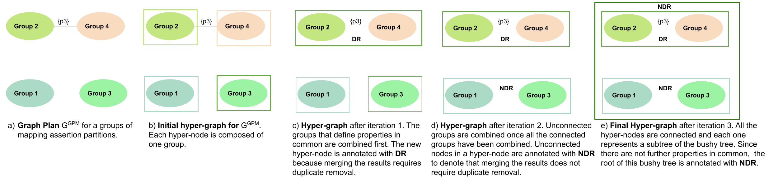
Figure 7a depicts a graph plan for the grouping named Optimized Partition in Figure 3. The graph is composed of four nodes and one edge, and outputs the set {p3} with the property that Group 2 and Grou p4 both define. Initially, Algorithm 1 creates a hyper-node with exactly one group in . Figure 7b depicts the initial configuration of the hyper-graph; it is composed of four hyper-nodes.
Hyper-nodes are sorted in based on the degree of connections and the cardinality of the labels of these connections, i.e., the number of properties that the connected groups have in common. Algorithm 1 resorts to this sorting to decide the order in which hyper-nodes will be merged. The first hyper-node in is selected and combined in a hypernode NewHN with the neighbor that shares more properties (BestNeighbor). The combined hyper-nodes (i.e., and BestNeighbor) are eliminated from and the new hyper-node (i.e., NewHN) is appended at the end of . If BestNeighbor and share at least one property in common (i.e., they were connected in the plan graph), NewHN is annotated with DR to denote that the duplicate removal needs to be executed. This decision implements our heuristic following the optimality principle P4. As a result, duplicate removal is first executed on the union of sets of RDF triples generated by mapping assertions that define the greatest number of properties in common, i.e., an eager evaluation of DR is scheduled. Contrary, if does not have a neighbor, a node with the highest number of connections is selected as best neighbor; NewHN is annotated with NDR to denote the union without duplicate removal. The process is repeated until a fixed point in the hyper-graph is reached; the generated hyper-graph corresponds to the bushy tree. Figures 7b, 7c, 7d, and 7e, illustrate the execution of Algorithm 1. The generated hyper-graph corresponds to the bushy tree illustrated in Figure 5a.

Theorem 5.1
Let be a graph plan of the groups in . Let be the cardinality, i.e., the number of groups in . The time complexity of Algorithm 1 is and up to bushy sub-plans are generated.
5.2 Executing Mapping Assertions
This step receives a bushy tree , and generates a physical plan that can execute the mapping assertions in following the order stated in . Figure 6 depicts the main two components of this step of the pipeline. First, nodes in are visited following a breadth-first traversal to generate a physical plan. A physical plan is defined in terms of operating system commands that enable the execution of a [R2]RML-compliant engine calls to evaluate a group of mapping assertions and generate RDF triples that will be part of a KG.
A physical plan is defined as:
Base Case. Let ECall, Time, File, and Id be an [R2]RML engine instruction call, execution timeout, group of mapping assertions file, and a process identifier, respectively. =&(timeout Time ECall wait %Id) represents that ECall is executed in the background until the process finalizes or times out after Time.
Inductive Case.
- •
Union with duplicate removal. Given two physical plans and whose execution produces RDF KGs and which may overlap. = &(sort -u ) represents that and are sorted, merged, and duplicates are removed.
- •
Union without duplicate removal. Given two physical plans and whose execution produces RDF KGs and which do not overlap. = &(cat ) represents that and are merged.
- •
Storing an RDF KG. Let be a plan whose execution generates a KG . = represents that is stored in the file .
The function represents the translation of the bushy tree into a physical plan ; is inductively defined over the structure of as follows:
Base Case. Let be a leaf, i.e., is a group of mapping assertions. Let ECall, Time, File, and BTId be an [R2]RML engine instruction call, execution timeout, group of mapping assertions file, and identifier, respectively.
=(timeout Time ECall wait %BTId)
Inductive Case I.
Let be a binary tree with the operator DR as root node:
=(sort -u &((BT1)) &((BT2)))
Inductive Case II. Let be a binary tree with the operator NDR as root node:
{forest}=(cat &((BT1)) &((BT2)))
Figure 8 depicts the physical plans generated following the inductive definition of . Three different plans are generated: the bushy, left-linear, and right-linear tree plans; the physical plans for each engine are also generated. In these trees, the duplicate removal operator is either pushed down into the tree (Figure 8 (a)) or in performed at the last step of the evaluation (Figures 8 (b) and (c)). The execution time of each physical plan is dominated by the cost of evaluating each group of mapping assertions. Nevertheless, the physical plan that implements the bushy tree requires only half of the time (i.e., 52.02% of the time consumed by the other physical plans) to combine the RDF triples generated during the execution of Group1, Group2, Group3, and Group4. These results provide evidence of the benefits of scheduling the execution of the KG creation following the physical plans generated by the proposed algorithms.
| Parameter: Dataset Size | ||
|---|---|---|
| Benchmark | Size | Description |
| GTFS-Madrid-Bench | 1-CSV | Ten different data sources are 4.8 Mb in total, where SHAPES.csv is the largest file with 4.5 Mb. |
| 5-CSV | Ten different data sources are 10 Mb in total, where SHAPES.csv is the largest file with 7.9 Mb. The KG generated from these data sources is five times bigger than the KG generated from 1-CSV. | |
| SDM-Genomic-Datasets | 10k | Each data source has 10,000 rows. |
| 100k | Each data source has 100,000 rows. | |
| 1M | Each data source has 1,000,000 rows. | |
| Parameters: Mapping Assertion (MA) Type and Complexity, Selectivity of the Results, and Type of Joins | ||
| Benchmark | Mapping Configuration | Description |
| GTFS-Madrid-Bench | Standard Config | 13 Concept MAs, 55 Attribute MAs, 73 single-source role MAs, and 12 multi-source role MAs. |
| SDM-Genomic-Datasets | Conf1 | One Concept MA, and one Attribute MA. |
| Conf2 | One Concept MA, and four Attribute MAs. | |
| Conf3 | Two Concept MA, one referenced-source role MA, and one attribute MA. | |
| Conf4 | Five Concept MAs, and four Referenced-source role MAs. | |
| Conf5 | Two Concepts MAs, and one Multi-source role MA. | |
| Conf6 | Five Concept MAs, and Four Multi-source role MAs | |
| AllTogether | Combines Conf1, Conf2, Conf3, Conf4, Conf5, and Conf6 into one mapping configuration. | |
| Conf7 | Four Concept MAs, and two Multi-source role MAs. This configuration seeks to evaluate the impact of defining the same predicates using different MAs. | |
| Conf8 | Six Concept and five Multi-source role MAs. This mapping configuration aims to recreate a five-star join where five MAs refer to the same parent MA. | |
| Conf9 | Eight Concept and seven Multi-source role MAs. This configuration combines Conf7 and Conf8 into one mapping configuration. | |
6 Experimental Study
The performance of the solution proposed to the problem of planning KG creation is studied in four RML-compliant engines: RMLMapper, RocketRML, SDM-RDFizer, and Morph-KGC. The code is publicly available on GitHub[37]. The empirical evaluation aims at answering the following research questions:
RQ1) How does planning the execution of mapping assertions affect the performance of the state-of-the-art RML-compliant engines during KG creation? RQ2) What is the impact of the type of mapping assertions and volume of the data sources on execution time and memory consumed by engines? RQ3) What is the impact in– execution time and memory consumption–of the execution of the mapping assertions following physical plans generated from bushy trees generated by Algorithm 1?6.1 Experimental Configuration
The following setting is configured to assess our research questions.
Benchmarks
Experiments are executed on datasets from GTFS-Madrid-Bench and SDM-Genomic-Datasets. Thus, our experimental setting can cover a larger spectrum of parameters that affect a KG creation task, i.e., dataset size, mapping assertion type and complexity, selectivity of the results, and types of joins between mapping assertions. Table 2 summarizes the main characteristics of these benchmarks and the covered parameters.
The GTFS-Madrid-Bench [22] benchmark enables the generation of different configurations of data integration systems whose characteristics impact on the process of KG creation. We generate four logical sources with the scaling factor 1-csv, 5-csv, 10-csv, and 50-csv. The scale value indicates that the comparison between the sizes of the goal KGs. For instance, a KG generated from 5-csv is five times larger than the KG that is created from 1-csv. The logical sources for the 1-csv configuration has in total 4.8 MB. In overall, we consider mapping rules comprised of 13 concept mapping assertions, 55 attribute mapping assertions, 73 single-source role mapping assertions, and 12 multi-source role mapping assertions involving ten data sources.
SDM-Genomic-Datasets [10] is a benchmark to compare the performance of state-of-the-art RML-compliant engines. SDM-Genomic-Datasets is created by randomly selecting data records from somatic mutation data collected in COSMIC [14]. SDM-Genomic-Datasets includes eight different logical data sources with various sizes including 10k, 100k, 1M, and 10M number of rows. Accordingly, every pair of logical data sources with the same size differ in data duplicate rates, which can be either 25% or 75%. Each duplicate value is repeated 20 times. For example, a 10k logical data source with 25% data duplicate rates has 75% duplicate-free records (i.e., 7,500 rows) and the rest of the 25% of the records (i.e., 2,500 rows) correspond to 125 different records which are duplicated 20 times. The SDM-Genomic-Datasets offers nine mapping assertion configurations.
We group the aforementioned mapping assertions into a set named AllTogether. Furthermore, the benchmark includes three extra configurations to enable the evaluation of the impact of two other influential parameters on the performance of KG creation frameworks [11]. Conf7 aims at evaluating the impact of defining the same predicates using different mapping assertions. Conf8 provides a mapping rule which is connected to five other mapping rules with different logical sources through join, i.e., this mapping assertion is connected via a five-star join with the other five mapping assertions. The last configuration or Conf9 combines the first two configurations in one testbed. Conf7: Set of four mapping assertions with four concepts and two multi-source role mapping assertions. For each pair of mapping assertions, there is a multi-source role mapping assertion. The data sources of one pair of the mapping assertions are a subset of the other pair. Both pairs of mapping assertions share the same predicate. Conf8: Set of six mapping assertions with six concepts and five multi-source role mapping assertions. In this set, five child mapping assertions are referring to the same parent mapping assertion. Conf9: Set of eight mapping assertions with eight concepts and seven multi-source role mapping assertions.


RML Engines
RMLMapper v4.12 [9], RocketRML v1.11.3 [58], Morph-KGC v1.4.1 [7], and SDM-RDFizer v3.6 [12]. Recently, SDM-RDFizer v4.0 [13] has been published. According to the tool description, SDM-RDFizer v4.0 implements planning techniques, physical operators for the execution of mapping assertions, and data compression techniques for reducing the size of the main memory structures required to store intermediate results. In order to create a fair evaluation of the performance of the techniques developed in SDM-RDFizer v4.0, we implement an upgraded version of SDM-RDFizer v3.6 which includes the data compression technique developed in SDM-RDFizer v4.0; we call this engine SDM-RDFizer v4.0--.
Implementations.
The planning and execution pipeline is implemented in Python 3. The compression techniques implemented in SDM-RDFizer v4.0-- encode RDF resources generated during the KG creation process. For each RDF resource R, an identification number i is assigned to it. Thus, RDF triples are built not from RDF resources but the identification number. Moreover, each identification number i is encoded in Base36 to reduce the memory usage further. Base36 is an encoding scheme that transforms a string into a 36 characters representation. The characters used are the letters from A to Z and the numbers from 0 to 9. For example, the number ”95634785” is encoded as ”1KXS9T”. The SDM-RDFizer operators are adapted to consider this compression method, consuming less main memory.
Metrics
We consider two metrics to evaluate the efficiency of our proposed approach. Execution time is defined as the elapsed time required to generate the bushy tree and execute the corresponding physical plan used to create the KG. It is measured as the absolute wall-clock system time, as reported by the time command of the Linux operating system. The leaves of a bushy tree are executed in parallel, and execution of the leaves corresponds to the greatest execution time; execution time also includes the time of merging the results generated during the execution of the tree leaves. Memory consumption is determined as the amount of memory that is consumed during the generation of a KG. The memory usage is measured by using the tracemalloc library from Python [15]. The get_traced_memory() method from tracemalloc returns the amount of memory currently being used. This method presents the memory usage in Kilobytes, for ease of use, it is converted into Megabytes. The timeout is five hours. The experiments are executed in an Intel(R) Xeon(R) equipped with a CPU E5-2603 v3 @ 1.60GHz 20 cores, 64GB memory and with the O.S. Ubuntu 16.04LTS.
All the resources used in the reported experimental study are publicly available [36].


6.2 Experiment 1- Efficiency on GTFS-Madrid-Bench
This experiment aims at evaluating the impact that grouping mapping assertions have on the performance of the state-of-the-art engines RMLMapper, RocketRML, and SDM-RDFizer v3.6. Using the algorithm of Grouping Mapping Assertions, ten groups of mapping assertions are generated, which are evaluated over the 1-csv and 5-csv data sources from GTFS-Madrid-Bench. Moreover, the full set of mapping assertions is executed by each engine considering both data sources. Figure 9 reports on the execution time (seconds in log scale) for each of the ten groups, as well as with No_Partition. The three engines can execute nine groups in less than five seconds and produce 15.63 of the overall RDF triples.
The group Shapes comprises four attribute mapping assertions and a multi-source role mapping assertion partition over one logical source named “Shapes”, i.e., the execution of this assertion requires a self-join. We further divided the group Shapes into two smaller partitions: Shapes-1 containing the four attribute mapping assertions and Shapes-2 containing the self-join.
We generate these smaller partitions because RMLMapper and RocketRML cannot complete the execution of the group Shapes.
The size of the logical source “Shapes” is 4.5MB in the case of 1-csv and 7.9MB in 5-csv. RocketRML is unsuccessful in finishing the evaluation of the self-join due to memory failure. Contrary, RMLMapper, and SDM-RDFizer succeed to execute this group of mapping assertions over the two studied versions of the data source “Shapes” (Figures 9(a) and 9(b)). RMLMapper produces the overall RDF triples of the “Shapes” in 2,707.32 seconds and 10,800.32 seconds in case of 1-csv and 5-csv, respectively. SDM-RDFizer also generates all the RDF triples of the “Shapes” in 284.06 seconds and 396.2 seconds for 1-csv and 5-csv, respectively.
In the case of No_Partition, RocketRML runs out of memory without generating any result, while RMLMapper and SDM-RDFizer both produce all the RDF triples.
In the optimized case, i.e., the time of executing the groups of assertions in parallel, RMLMapper requires, respectively, 91.42 and 80.87 in 1-csv and 5-csv of the time No_Partition.
Likewise, the proposed planning techniques also speed up the SDM-RDFizer execution concerning No Partition; it consumes, respectively, 96.32 and 79.50 in 1-csv and 5-cvs of the execution time of No_Partition.
Although savings are observed, the evaluation of the Shapes group consumes the majority of the execution time of the corresponding physical plan. This prevents observing the benefits of executing the mapping assertions in parallel.
It is also important to highlight that even though this benchmark, allows for configuring testbeds that produce KGs of various sizes, the scaling factor is not equally applied to all the data sources and RDF triples produced by each mapping assertion.
Conversely, most of the new RDF triples produced by a high-scaled KG are generated by the Shapes group. This lack of diversity also prevents observing differences in different configurations, i.e., 1-csv and 5-csv.
6.3 Experiment 2- Efficiency on SDM-Genomic-Datasets
This experiment aims to assess the impact of planning on a real-world dataset such as the one provided by the SDM-Genomic-Datasets. Although the mapping assertions defined for the SDM-Genomic-Datasets are much simpler compared to the ones in GTFS-Madrid-Bench, they cover all the different types of mapping assertions presented in section 2.


We study the performance of each engine, i.e., RocketRML, RMLMapper, and SDM-RDFizer in presence and absence of planning using SDM-Genomic-Datasets. In addition to the six configurations of mapping assertions, i.e., Conf1, Conf2, Conf3, Conf4, Conf5, and Conf6, we consider an additional configuration consisting of the union of all them.

We refer to it as AllTogether. As illustrated in Figure 10, in the case of having referenced-source role mapping assertions (i.e., Conf3 and Conf4), neither of the two engines, RMLMapper and RocketRML, is able to complete the execution before the timeout. As observed in Figure 10, applying planning in simple cases like Conf1, Conf2, and Conf3 with low data duplicate rates does not show a considerable impact on the performance.

Conversely, in complex cases such as Conf6 which include several multi-source role mapping assertions, execution time is reduced significantly exploiting planning. Unfortunately, both RMLMapper and RocketRML lack efficient implementations of the operators that are required to execute referenced-source role mapping assertions.
Therefore, the two mentioned engines are unable to finish the execution of Conf3 and Conf4 before the timeout (i.e., 5 hours). The results in Figure 10 also suggest that with the growth of duplicate data rate, the benefits of using the proposed planning techniques also increased.
| Percentage of Duplicates: 25% | ||||||||||
|---|---|---|---|---|---|---|---|---|---|---|
| Size | Engine | Conf7 | Conf8 | Conf9 | ||||||
| Original | Optimized | % Savings | Original | Optimized | % Savings | Original | Optimized | % Savings | ||
| 10k | SDM-RDFizer | 3.91 sec | 5.04 sec | -28.90 % | 5.59 sec | 6.54 sec | -16.99 % | 10.7 sec | 6.47 sec | 39.53% |
| RMLMapper | 47.43 sec | 36.69 sec | 22.64 % | 140.27 sec | 43.93 sec | 68.68 % | 180.85 sec | 43.25 sec | 76.09 % | |
| Morph-KGC | 1.81 sec | 3.55 sec | -96.13% | 1.79 sec | 4.22 sec | -135.75 % | 2.28 sec | 5.2 sec | -128.07 % | |
| 100k | SDM-RDFizer | 21.14 sec | 16.88 sec | 20.15 % | 99.88 sec | 51.11 sec | 48.82 % | 105.72 sec | 44.97 sec | 57.46 % |
| RMLMapper | 3205.37 sec | 2628.13 sec | 18.01 % | 11961.81 sec | 3901.14 sec | 67.38 % | 12593.16 sec | 3401.17 sec | 72.99 % | |
| Morph-KGC | 20.4 sec | 19.35 sec | 5.14 % | 43.87 sec | 29.38 sec | 33.02 % | 42.43 sec | 30.84 sec | 27.31 % | |
| 1M | SDM-RDFizer | 177.35 sec | 124.08 sec | 30.03 % | 1656.29 sec | 607.06 sec | 63.34 % | 1769.29 sec | 685.22 sec | 61.27 % |
| RMLMapper | TimeOut | TimeOut | - | TimeOut | TimeOut | - | TimeOut | TimeOut | - | |
| Morph-KGC | 1532.94 sec | 1224.37 sec | 20.13 % | 3369.11 sec | 2154.92 sec | 36.03 % | 3329.16 sec | 2071.63 sec | 37.77 % | |
| Percentage of Duplicates: 75% | ||||||||||
| Size | Engine | Conf7 | Conf8 | Conf9 | ||||||
| Original | Optimized | %Savings | Original | Optimized | %Savings | Original | Optimized | %Savings | ||
| 10k | SDM-RDFizer | 3.6 sec | 4.89 sec | -35.83 % | 4.44 sec | 5.44 sec | -22.52 % | 8.35 sec | 5.85 sec | 29.94 % |
| RMLMapper | 38.82 sec | 35.41 sec | 8.78 % | 133.96 sec | 47.01 sec | 64.90 % | 173.08 sec | 47.64 sec | 72.47 % | |
| Morph-KGC | 2.15 sec | 4.01 sec | -86.51% | 2.11 sec | 4.59 sec | -117.53% | 2.93 sec | 5.33 sec | -81.91% | |
| 100k | SDM-RDFizer | 19.72 sec | 16.16 sec | 18.05% | 70.5 sec | 31.06 sec | 55.94% | 66.15 sec | 29.97 sec | 54.69% |
| RMLMapper | 3203.19 sec | 2672.59 sec | 16.56% | 12669.84 sec | 3861.29 sec | 69.52% | 16541.84 sec | 3985.06 sec | 75.90% | |
| Morph-KGC | 23.53 sec | 22.21 sec | 5.60% | 46.35 sec | 35.7 sec | 22.97% | 48.13 sec | 35.68 sec | 25.86% | |
| 1M | SDM-RDFizer | 174.11 sec | 123.77 sec | 28.91% | 983.53 sec | 402.59 sec | 59.06% | 1252.27 sec | 516.99 sec | 58.71% |
| RMLMapper | TimeOut | TimeOut | - | TimeOut | TimeOut | - | TimeOut | TimeOut | - | |
| Morph-KGC | 1628.69 sec | 1330.01 sec | 18.33% | 3338.93 sec | 2229.78 sec | 33.21% | 3641.57 sec | 2200.08 sec | 39.58% | |
6.4 Experiment 3- Efficiency on Large Datasets
This experiment evaluates the impact of a data source size on memory usage during the KG creation process. For this purpose, four data sources with different sizes are generated using the GTFS-Madrid-Bench including 1-csv, 5-csv, 10-csv, and 50-csv. Since RMLMapper and RocketRML are not able to scale up to large data sources, we compare the performance of SDM-RDFizer v4.0 in absence and presence of planning; we refer to the latest one as SDM-RDFizer v4.0--+Planning. We evaluate the performance of the mentioned versions in terms of both execution time (in second) and main memory consumption (MB); the results of both are reported in log scale. As demonstrated in Figures 11a and 11b both versions of SDM-RDFizer are able to complete the KG creation process for all the datasets. Additionally, it can be observed that the planning reduces the memory usage and execution time in each dataset. The observed results in Figure 11a and Figure 11b suggest that the impact of our proposed planning techniques in the enhancement of the performance of SDM-RDFizer v4.0-- is higher than the planning techniques implemented by SDM-RDFizer v4.0.
6.5 Experiment 4- Efficiency on Complex Mappings
This experiment aims at assessing the effect of the complex mapping assertions on the execution time during the KG creation process. In these experiments, RocketRML is replaced by Morph-KGC since RocketRML is unable to execute the multi-source mapping assertions that composed the Conf7, Conf8, and Conf9.
Figures 12 and 13 report on execution time (log scale) and Table 3 presents the specific values of each execution.
As observed, the RMLMapper performance is improved in Conf7, Conf8, and Conf9 even in data sources of small size, i.e., 10k.
In the data source of the size 10k, there is reduction of execution time for Conf7 with duplicate rate and reduction with duplicate rate, reduction for Conf8 with duplicate rate and reduction with duplicate rate, and reduction for Conf9 with duplicate rate and reduction with duplicate rate. For 100k, there is a reduction of execution time for Conf7 with duplicate rate and reduction with duplicate rate, a reduction for Conf8 with duplicate rate and reduction with duplicate rate, and a reduction for Conf9 with duplicate rate and reduction with duplicate rate.
The RMLMapper timed out after 5 hours with both methods when executing the 1M data sources with all three mappings with duplicate rates. This can be attributed to how the execution of the join is implemented in the RMLMapper and the size of the data. But with the planned execution, it could generate at least a portion of the KG for each mapping. For Conf7, Conf8, and Conf9, respectively, , , and of the KG are generated.
For the SDM-RDFizer and Morph-KGC, there was overhead when generating the KG for Conf7 and Conf8 with 10k. This can be attributed to the fact that both the SDM-RDFizer and Morph-KGC already have optimization techniques implemented. Combining the optimization techniques and the physical plan causes the overhead in cases with small data sources, i.e., 10k. While for Conf9, there is a reduction with duplicate rate and a reduction with duplicate rate for the SDM-RDFizer when using the planned execution. There are savings of 100k and 1M when using the planned execution for both engines. In particular, Conf9 presents the highest savings. For 100k, there is a reduction with duplicate rate and a reduction with duplicate rate for the SDM-RDFizer and a reduction with duplicate rate and a reduction with duplicate rate for Morph-KGC.
For 1M, there is a reduction with duplicate rate and a reduction with duplicate rate for the SDM-RDFizer and a reduction with duplicate rate and a reduction with duplicate rate for Morph-KGC. This increase in savings is related to the complexity of the mapping; higher complexity causes higher savings.
In conclusion, applying the proposed planning techniques reduces the execution time, independent of the engine by which they are adopted. However, applying these techniques in engines such as SDM-RDFizer and Morph-KGC, which already perform optimization techniques, may cause an overhead.
Specifically, in the case of having small size data sources or less complex mapping assertions, the cost of planning in addition to the other optimization techniques implemented in the engine can be higher than the savings. Like any optimization technique, there is a trade-off that can be estimated based on the provided data integration system. The higher the complexity of the mapping assertions and dataset size, the higher the execution time improvement.
6.6 Discussion
Answer to RQ1. There exist configurations of data integration systems where the proposed planning techniques improve the performance of any state-of-the-art engines. The experimental results provide insights on the cases where planning improves the KG creation frameworks in contrast to the ones that it may cause negative impact. E.g., in case of having small data sources or simple mapping assertions, the execution times of SDM-RDFizer and Morph-KGC are lower ignoring the planning of the mapping assertions. However, it is important to note that execution planning empowers state-of-the-art engines without continuous behavior to generate a partial KG output. In other words, the generated plans enable some engines to produce outputs instead of timing out or running out of memory.
Answer to RQ2. Attribute mapping assertion presents the shortest execution time of all the types of mapping assertion since they represent a simple projection of the raw data. In terms of memory usage, attribute mapping assertion dependent on the size of the data source, meaning larger data sources cause greater memory usage. The execution time of a multi-source role mapping assertion depends on the size of the data sources and the number of values associated with them. Larger data sources and a more significant number of associated values imply higher memory usage. The execution time of referenced-source role mapping assertions depends on the size of the data source and the data management techniques implemented for each engine. RMLMapper and RocketRML execute the mentioned operation as a Cartesian product, causing the execution time to grow exponentially and, by extension, the memory usage.
Answer to RQ3. Algorithm 1 generates a bushy tree, which schedules which mapping assertions should be executed together because of the number of predicates or data sources in common. Executing mapping assertions following a bushy tree plan reduces both execution time and memory usage. In attribute mapping assertions with the same data source or referenced source, role mapping assertions have minimal impact on execution time and memory usage. Since all mapping assertions in question use the same data source, only one partition would be used. For multi-source role mapping assertion, Algorithm 1 generates bushy trees whose execution positively influences time and memory. This behavior is achieved by partitioning mapping assertions that reduce the number of operations per group. Therefore, the workload, execution time, and memory usage are reduced.
7 Conclusions and Future Work
We address the problem of efficient KG creation. This problem is of paramount relevance given the momentum that KGs have gained in science and industry, as well as declarative processes to specify KGs. We present heuristic-based solutions that, following greedy algorithms, can identify execution plans that can efficiently generate KGs. The empirical evaluation of the proposed methods empowers existing RML-compliant engines and enables them to scale to complex situations. The execution planning techniques partition mapping assertions and schedule them into execution plans that consume less memory and reduce execution time. Thus, the proposed planning methods evidence the crucial role that optimization techniques– defined in the context of query processing– also have in the KG creation process. Moreover, the reported results put in perspective the need of specialized data management methods for scaling up KG creation to complex data integration systems present in real-world applications. Albeit efficiently defined, execution planning may be costly and generate overhead, which negatively impact engine behavior in simple cases. In the future, we will research lightweight cost-based planning methods to estimate more efficient execution schedulers.
Acknowledgements
This work has been partially supported by the EU H2020 RIA funded project CLARIFY with grant agreement No 875160 and PLATOON (GA No. 872592). Federal Ministry for Economic Affairs and Energy of Germany in the project CoyPu (project number 01MK21007[A-L]. Furthermore, Maria-Esther Vidal is partially supported by the Leibniz Association in the program ”Leibniz Best Minds: Programme for Women Professors”, project TrustKG-Transforming Data in Trustable Insights with grant P99/2020.
References
- [1] Big Data for medical analytics. https://www.bigmedilytics.eu/. Accessed: 10-09-2022.
- [2] Big Data for precision medicine. https://project-iasis.eu/. Accessed: 10-09-2022.
- [3] Cancer Long Survivors artificial intelligence follow up. https://www.clarify2020.eu/. Accessed: 10-09-2022.
- [4] Cognitive Economy Intelligence plattform für die resilienz wirtschaftlicher Ökosysteme. https://CoyPu.org/. Accessed: 10-09-2022.
- [5] The federal ministry for economic affairs and climate action. https://www.bmwk.de/. Accessed: 10-09-2022.
- [6] Genomic, mapping assertions. https://github.com/SDM-TIB/IASIS-KG/tree/master/settings/mappings/genomic. Accessed: 10-12-2021.
- [7] Morph-KGC: v1.4.1. https://github.com/oeg-upm/Morph-KGC. Accessed: 24-06-2022.
- [8] R2RML: rdb to rdf mapping language. https://www.w3.org/TR/r2rml/. Accessed: 24-06-2022.
- [9] RMLMapper: v4.12. https://github.com/RMLio/rmlmapper-java. Accessed: 24-06-2022.
- [10] SDM-Genomic, datasets. https://doi.org/10.6084/m9.figshare.14838342.v1. Accessed: 24-06-2022.
- [11] SDM-Genomic, mapping assertions. https://doi.org/10.6084/m9.figshare.17142371. Accessed: 24-06-2022.
- [12] SDM-RDFizer: v3.6. https://pypi.org/project/rdfizer/3.6/. Accessed: 24-06-2022.
- [13] SDM-RDFizer: v4.0. https://pypi.org/project/rdfizer/4.0/. Accessed: 24-06-2022.
- [14] COSMIC, catalogue of somatic mutations in cancer. grch37, version90. https://cancer.sanger.ac.uk/cosmic, 2019. Accessed: 10-12-2021.
- [15] Tracemalloc: version 3.4. https://docs.python.org/3/library/tracemalloc.html, 2020. Accessed: 24-06-2022.
- [16] J. Arenas-Guerrero, D. Chaves-Fraga, J. Toledo, M. S. Pérez, and O. Corcho. Morph-kgc: Scalable knowledge graph materialization with mapping partitions. Semantic Web, 2022.
- [17] C. Badenes-Olmedo, D. Chaves-Fraga, M. Poveda-Villalón, A. Iglesias-Molina, P. Calleja, S. Bernardos, P. Martín-Chozas, A. Fernández-Izquierdo, E. Amador-Domínguez, P. Espinoza-Arias, L. Pozo-Gilo, E. Ruckhaus, E. González-Guardia, R. Cedazo, B. López-Centeno, and Ó. Corcho. Drugs4covid: Drug-driven knowledge exploitation based on scientific publications. CoRR, abs/2012.01953, 2020.
- [18] J. Barroca, A. Shivkumar, B. Q. Ferreira, E. Sherkhonov, and J. Faria. Enriching a fashion knowledge graph from product textual descriptions. arXiv preprint arXiv:2206.01087, 2022.
- [19] S. Benbernou, X. Huang, and M. Ouziri. Semantic-based and entity-resolution fusion to enhance quality of big rdf data. IEEE Transactions on Big Data, 2017.
- [20] C. Bizer, C. Becker, P. N. Mendes, R. Isele, A. Matteini, and A. Schultz. Ldif-a framework for large-scale linked data integration. 2012.
- [21] D. Chaves-Fraga, K. M. Endris, E. Iglesias, Ó. Corcho, and M. Vidal. What are the parameters that affect the construction of a knowledge graph? In ODBASE, 2019.
- [22] D. Chaves-Fraga, F. Priyatna, A. Cimmino, J. Toledo, E. Ruckhaus, and O. Corcho. Gtfs-madrid-bench: A benchmark for virtual knowledge graph access in the transport domain. Journal of Web Semantics, 65:100596, 2020.
- [23] D. Chaves-Fraga, E. Ruckhaus, F. Priyatna, M. Vidal, and Ó. Corcho. Enhancing virtual ontology based access over tabular data with morph-csv. Semantic Web, 12(6), 2021.
- [24] A. Chessa, G. Fenu, E. Motta, D. Reforgiato Recupero, F. Osborne, A. Salatino, and L. Secchi. Enriching data lakes with knowledge graphs.
- [25] C. X. Chu, S. Razniewski, and G. Weikum. Knowfi: Knowledge extraction from long fictional texts. In 3rd Conference on Automated Knowledge Base Construction, 2021.
- [26] D. Collarana, M. Galkin, I. Traverso-Ribón, M.-E. Vidal, C. Lange, and S. Auer. Minte: semantically integrating rdf graphs. In Proceedings of the 7th International Conference on Web Intelligence, Mining and Semantics, 2017.
- [27] S. Das, S. Sundara, and R. Cyganiak. R2RML: RDB to RDF Mapping Language, W3C Recommendation 27 September 2012. W3C, 2012.
- [28] B. De Meester, A. Dimou, R. Verborgh, and E. Mannens. An ontology to semantically declare and describe functions. In European Semantic Web Conference, pages 46–49. Springer, 2016.
- [29] C. Debruyne and D. O’Sullivan. R2RML-F: Towards Sharing and Executing Domain Logic in R2RML Mappings. In LDOW Workshop, 2016.
- [30] A. Dimou, T. De Nies, R. Verborgh, E. Mannens, and R. Van de Walle. Automated metadata generation for Linked Data generation and publishing workflows. In S. Auer, T. Berners-Lee, C. Bizer, and T. Heath, editors, Proceedings of the 9th Workshop on Linked Data on the Web, volume 1593 of CEUR Workshop Proceedings, Apr. 2016.
- [31] A. Dimou, T. D. Nies, R. Verborgh, E. Mannens, and R. V. de Walle. Automated metadata generation for linked data generation and publishing workflows. In S. Auer, T. Berners-Lee, C. Bizer, and T. Heath, editors, Proceedings of the Workshop on Linked Data on the Web, LDOW 2016, co-located with 25th International World Wide Web Conference (WWW 2016), volume 1593 of CEUR Workshop Proceedings. CEUR-WS.org, 2016.
- [32] A. Dimou, M. V. Sande, P. Colpaert, R. Verborgh, E. Mannens, and R. V. de Walle. RML: A generic language for integrated RDF mappings of heterogeneous data. In Proceedings of the Workshop on Linked Data on the Web co-located with WWW, 2014.
- [33] G. Gawriljuk, A. Harth, C. A. Knoblock, and P. Szekely. A scalable approach to incrementally building knowledge graphs. In International Conference on Theory and Practice of Digital Libraries, 2016.
- [34] C. Gutiérrez and J. F. Sequeda. Knowledge graphs. Communications of the ACM, 64(3):96–104, 2021.
- [35] E. Iglesias, S. Jozashoori, D. Chaves-Fraga, D. Collarana, and M.-E. Vidal. Sdm-rdfizer: An rml interpreter for the efficient creation of rdf knowledge graphs. In Proceedings of the 29th ACM International Conference on Information & Knowledge Management, pages 3039–3046, 2020.
- [36] E. Iglesias, S. Jozashoori, and M.-E. Vidal. Planning for KGs: experimental study. https://github.com/SDM-TIB/Planning4KGC. Accessed: 10-09-2022.
- [37] E. Iglesias, S. Jozashoori, and M.-E. Vidal. RML-Planner: scaling up knowledge graph creation to larger and heterogeneous data sources. https://github.com/SDM-TIB/RML-Planner. Accessed: 10-09-2022.
- [38] R. Isele and C. Bizer. Active learning of expressive linkage rules using genetic programming. Journal of web semantics, 23:2–15, 2013.
- [39] V. Janev, M.-E. Vidal, D. Pujić, D. Popadić, E. Iglesias, A. Sakor, and A. Čampa. Responsible knowledge management in energy data ecosystems. Energies, 15(11), 2022.
- [40] S. Jozashoori, D. Chaves-Fraga, E. Iglesias, M.-E. Vidal, and O. Corcho. Funmap: Efficient execution of functional mappings for knowledge graph creation. In International Semantic Web Conference, pages 276–293. Springer, 2020.
- [41] S. Jozashoori, A. Sakor, E. Iglesias, and M.-E. Vidal. Eablock: a declarative entity alignment block for knowledge graph creation pipelines. In Proceedings of the 37th ACM/SIGAPP Symposium On Applied Computing, pages 1908–1916, 2022.
- [42] S. Jozashoori and M.-E. Vidal. Mapsdi: a scaled-up semantic data integration framework for knowledge graph creation. In OTM Confederated International Conferences” On the Move to Meaningful Internet Systems”, pages 58–75. Springer, 2019.
- [43] A. C. Junior, C. Debruyne, R. Brennan, and D. O’Sullivan. FunUL: a method to incorporate functions into uplift mapping languages. In Intern. Confer. on Information Integration and Web-based Applications and Services, 2016.
- [44] M. Kejriwal, J. F. Sequeda, and V. Lopez. Knowledge graphs: Construction, management and querying. Semantic Web, 10(6), 2019.
- [45] C. A. Knoblock and P. Szekely. Exploiting semantics for big data integration. AI Magazine, 36(1), 2015.
- [46] A. Krithara, F. Aisopos, V. Rentoumi, A. Nentidis, K. Bougiatiotis, M. Vidal, E. Menasalvas, A. R. González, E. Samaras, P. Garrard, M. Torrente, M. P. Pulla, N. Dimakopoulos, R. Mauricio, J. R. D. Argila, G. G. Tartaglia, and G. Paliouras. iasis: Towards heterogeneous big data analysis for personalized medicine. In 32nd IEEE International Symposium on Computer-Based Medical Systems, CBMS 2019, pages 106–111. IEEE, 2019.
- [47] M. Lefrançois, A. Zimmermann, and N. Bakerally. A sparql extension for generating rdf from heterogeneous formats. In European Semantic Web Conference, pages 35–50. Springer, 2017.
- [48] M. Lenzerini. Data integration: A theoretical perspective. In ACM Symposium on Principles of Database Systems, 2002.
- [49] P. Maria. CARML: a pretty sweet rml engine. https://github.com/carml/carml. Accessed: 24-06-2022.
- [50] P. N. Mendes, H. Mühleisen, and C. Bizer. Sieve: linked data quality assessment and fusion. In Proceedings of the 2012 Joint EDBT/ICDT Workshops, pages 116–123, 2012.
- [51] M. Namici and G. De Giacomo. Comparing query answering in obda tools over w3c-compliant specifications. In Description Logics, 2018.
- [52] F. Priyatna, Ó. Corcho, and J. F. Sequeda. Formalisation and experiences of r2rml-based SPARQL to SQL query translation using morph. In C. Chung, A. Z. Broder, K. Shim, and T. Suel, editors, World Wide Web Conference, WWW, 2014.
- [53] W. Scheufele and G. Moerkotte. On the complexity of generating optimal plans with cross products. In A. O. Mendelzon and Z. M. Özsoyoglu, editors, Proceedings of the Sixteenth ACM SIGACT-SIGMOD-SIGART Symposium on Principles of Database Systems, 1997.
- [54] P. Szekely, C. A. Knoblock, J. Slepicka, A. Philpot, A. Singh, C. Yin, D. Kapoor, P. Natarajan, D. Marcu, K. Knight, et al. Building and using a knowledge graph to combat human trafficking. In International Semantic Web Conference, 2015.
- [55] J. Teuhola and L. M. Wegner. Minimal space, average linear time duplicate deletion. Commun. ACM, 34(3):62–73, 1991.
- [56] M. Vidal, K. M. Endris, S. Jazashoori, A. Sakor, and A. Rivas. Transforming heterogeneous data into knowledge for personalized treatments - A use case. Datenbank-Spektrum, 19(2):95–106, 2019.
- [57] B. Vu, J. Pujara, and C. A. Knoblock. D-REPR: A Language for Describing and Mapping Diversely-Structured Data Sources to RDF. In Intern. Confer. on Knowledge Capture, 2019.
- [58] U. Şimşek, E. Kärle, and D. Fensel. Rocketrml - a nodejs implementation of a use-case specific rml mapper, 2019. Accessed: 24-06-2022.
Appendix 0.A Theorems and Proofs
0.A.1 Theorem of Optimality
Theorem 4.1. Let be a data integration system such that assertions in meet the following conditions:
- •
A concept mapping assertion on source is referred from any number of multi-source role mapping assertions , but these assertions are all from one source .
- •
A property from is defined, at most, on one mapping assertion .
Let be a bushy tree plan over mapping assertions in and data sources in ; generates and respects the optimality principles P1-P4. Then, is optimal, i.e., there is no other equivalent bushy tree plan such as .
Proof. By contradiction. Assume respects the optimality principles P1-P4, but there is a different bushy tree plan , i.e., the executions of and produce the same RDF triples when evaluated on the same engine, and .
Base Case
Suppose is an intra-source partition that includes all the mapping assertions over a source , i.e., concept, attribute, and single-source and referenced-source role mapping assertions. is an equivalent bushy tree plan, but it is different from . It comprises at least two intra-source partitions for the mapping assertions in . These partitions contain only assertions over ; for hypothesis, a predicate can be defined by at most one mapping assertion. However, this would lead to a contradiction because the execution of will require loading in memory several times, during the evaluation of the two intra-source partitions and .
Suppose is an inter-source partition over sources and , which are related via multi-source role mapping assertions.
includes all the multi-source role mapping assertions from to the concept mapping assertion over , and all the attribute, single-source, and referenced-source role mapping assertions over . Note that by hypothesis, the concept mapping assertion over is referred from only multi-source role mapping assertions over .
An equivalent plan should have at least two partitions, i.e., and . Without lost of generality, assume that is an intra-source partition over , while comprises the multi-source role mapping assertions on that refer to . and collect data from , and both upload independently. Thus, , leading, thus, a contradiction.
Inductive Hypothesis
and are optimal bushy plans for .
Induction Step
Suppose comprises sub-plans and and the union operator . Let an equivalent bushy tree plan. Without lost of generality, assume implements the eager evaluation of operators to eliminate duplicates of a property , while follows a lazy evaluation. If is required, the instances of are generated during the execution of at least two partitions.
However, this leads to a contraction, since by hypothesis, every predicate is defined by at most one mapping assertion, which should be included in only one partition, either in or , because both are optimal. ∎
0.A.2 Time Complexity of Algorithm 1
Theorem 5.1. Let be a graph plan of the groups in . Let be the cardinality, i.e., the number of groups in . The time complexity of Algorithm 1 is and up to bushy sub-plans are generated.
Proof. Algorithm 1 traverses the space of bushy tree plans in iterations until a fixed point on hyper-graph is reached. Initially, the partitions (i.e., nodes) are sorted based on degree in the graph plan and number of shared properties; this is done in . Then, in the first iteration, hyper-nodes are generated in the hyper-graph, each one composes one group in . Next, the nodes are visited in the identified order, and hyper-nodes are created. This process continues until iteration . In total, up to hyper-nodes are generated. These hyper-nodes correspond to bushy sub-plans. ∎