Neutron availability in the Complementary Experiments Hall
of the IFMIF-DONES facilityJournal: Fusion Engineering and Design
Abstract
The IFMIF-DONES facility will be dedicated to the irradiation of structural materials planned for the use in future fusion reactors such as DEMO (Demonstration Fusion Power Plant). The potentialities of the IFMIF-DONES facility to complement its principal purpose by other experiments that would open the facility to other communities is addressed in this work. It concerns a study based on simulations to evaluate the neutronic performances of IFMIF-DONES in an hall dedicated to complementary experiments where neutrons can be transported. With the simple beam tube geometry of 4.5 cm entrance diameter studied in this work we have shown that a collimated fast-neutron beam of about 2 1010 n/cm2/s is available in the hall. Adding a moderator in the hall with neutron extraction lines would allow to get thermal neutron beams of about 106-107 n/cm2/s for dedicated experiments. The results show that IFMIF-DONES has the potentialities to be a medium-flux neutron facility for most of the neutron applications.
1 Introduction
Neutrons are unique tools to probe matter and its bulk properties. They can reveal what other techniques cannot see. Therefore, they provide a powerful tool for investigating the natural world and have long played a role at the forefront of modern scientific research.
At the elementary and cosmological levels, neutrons provide very precise tests of the standard model of particle physics [1]. Moreover, the neutron lifetime is an important quantity that governs the primordial nucleosynthesis of elements a few seconds after the big bang. The neutron could also bring some of the answers on the origin of the matter-antimatter asymmetry in the universe and probe gravity at small scale [2].
In material and biological sciences, neutrons are unique to scrutinise both the structure and dynamics of atoms and molecules over a large range of distances and times. Compared to other standard techniques, as X-rays for example, neutrons scatter on nuclei instead of scattering on electrons offering a larger penetration in matter for most elements. Their interaction with hydrogen atoms allows very precise studies of organic materials as polymers, proteins, liquid crystals, etc…. Moreover, neutrons are very sensitive to magnetic fields allowing the study of magnetic materials.
Neutrons have also a wide range of applications in neutron radiography and tomography for various fields of science as life science, geology, archaeology but also for non-destructive testing of industrial components [3]. They play also an important role in nuclear medicine for radioisotope productions [4].
The IFMIF-DONES (International Fusion Materials Irradiation Facility - DEMO Oriented NEutron Source) [5] is a project of an accelerator based deuterium-lithium neutron source for irradiation of fusion reactor materials. A 125 mA beam of 40 MeV deuterons will strike a liquid Li target and produce an unprecedented high flux of neutrons with energies up to 50 MeV. It is part of an international effort to pave the road toward fusion energy. Fusion material irradiations will take place in the high-flux test module (HFTM) located in the test cell, the central confinement to envelop the end section of the deuteron accelerator and the target. The HFTM will be placed close to the Lithium target to benefit from the maximum neutron flux amounting to about n/cm2/s [6]. A large part of the neutrons will interact with the materials to be irradiated but most of them will just scatter-off or pass through the irradiation module and will be lost in the walls of the test cell bio-shield.
An effort, in the framework of the IFMIF-DONES Preparatory Phase [7], has been conducted to study the possibility of using neutrons for other experiments in a dedicated hall [8]. This hall will be adjacent to the test cell bio-shield, a neutron beam line passing through the bio-shield and allowing neutrons to be transported from the test cell to the hall.

The paper reports the simulation work performed to characterise the neutron beams that will be available in the complementary experiments hall (see Figure 1). It is organised as follows. In section 2, we present the methodology and software used in our study. Next, the neutron beam characteristics that would be available in the hall are given in section 3 for unmoderated neutrons together with background. And finally, the various fluxes which could be available in the hall as a function of the setup chosen are displayed in section 4.
2 Methodology and software tools
The global methodology followed in this work relies on Monte-Carlo simulations to evaluate and optimise the neutronic performances of the installation.
Simulations are based on Geant4.10.7 [9] using the TOUCANS (TOolkit for a Unified Compact Accelerator Neutron Sources design) toolkit [10] and MCNP6.2 (Monte Carlo N-Particle Transport Code System Version 6.2) [11]. TOUCANS is a modular code using Geant4 C++ libraries. It is developed at CEA Saclay since 2019 to design Compact Accelerator Neutron Sources (CANS) and to evaluate their neutronic performances. Geant4 (GEometry ANd Tracking) is a framework developed at CERN for the simulation of the passage of particles through matter by the Monte-Carlo method. Monte Carlo N-Particle or MCNP is a general-purpose Monte Carlo radiation transport code designed to track many particle types over broad ranges of energies. It is registered trademark owned by Triad National security, manager and operator of Los-Alamos National Laboratory (LANL).
The neutron transport in Geant4.10.7 at low energy was validated on experimental measurements (see ref. [12] and references therein). More recently, it has been benchmarked for cold moderators with Tripoli-4 [13], a transport Monte Carlo code developed at CEA for reactor physics with depletion, criticality and safety. The benchmark showed a perfect agreement between the two codes [10].
The simulations carried out with Geant4 were based on the physics list QGSP_BIC_AllHP.
The double differential neutron spectrum inside the test cell used as input for Geant4 simulations was calculated by means of the MCNP-6 code using the DONES model “mdl9.2.1”, which includes the updated HFTM and test cell configuration. In that simulation, the package McDeLicious-17 [14] was capitalised on to simulate the D-Li reactions. The neutron FENDL-3.1d library [15] was employed. The results were normalised to a 125 mA beam of 40 MeV deuterons impinging the lithium target.
The source term for the Geant4 simulations was extracted from these simulations by fixing a circle with a radius of 2.25 cm at the entrance of the inlet. In this configuration, the neutron current at the entrance of the beam tube is 1.835 1013 n/s (1.15 1012 n/s/cm2) as shown in Figure 2. This source term is available in the complementary material of this article.

The number of simulated histories in MCNP-6 simulations was 2 1010 to get sufficient statistics. In the case of Geant4, the number of simulated histories was highly variable as a function of observables studied. This number varies between for the most accessible observables and when statistic was needed.
3 Unmoderated neutron beam in the hall
3.1 Neutron characteristics
The case of reference chosen in this work is a beam line of conical shape to transport neutrons from the test cell to the complementary experiments hall (see Figure 1). The beam tube is constituted of three cylindrical iron tubes of 4.5 cm, 6 cm and 9 cm in diameters with respective length of 1 m, 1.7 m and 3.7 m. This shape allows to follow the natural dispersion of the neutrons to maximize the neutron flux in the hall but a cylindrical shape could be adopted if a better collimation is needed. It is aligned on the deuteron beam axis and tilted by 9° with respect to the test cell bio-shield wall. In the configuration studied here, the bio-shield thickness is 6.4 m.

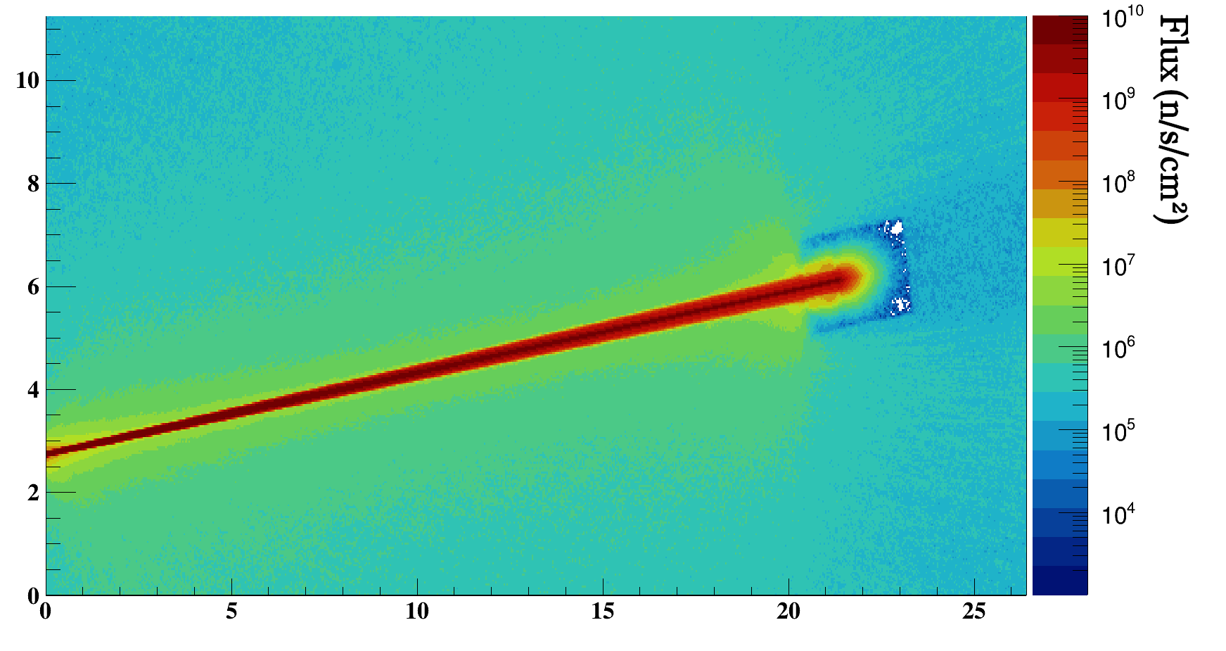
The neutron beam characteristics at the entrance of the hall are shown in Figure 3, 4, 5, and 6. The beam is very well collimated with a global divergence of less than 1 degree (see Figure 4). However, there is no beam structure and therefore, Time of Flight (ToF) technique cannot be used. This is compensated by a very high neutron flux in comparison to other facilities. A tabulation of the neutron flux at the entrance of the hall as a function of the energy and the angle of emission is available in the complementary material.


With this configuration of beam tube, the neutron flux emerging in the hall amounts to a total of 2 1010 n/cm2/s with a majority (99.5%) of fast neutrons (En > 100 keV) to be compared with the neutron flux in the test cell at the entrance of the collimator (1012 n/cm2/s). The energy distribution remains the same along the collimator for the energies above 5 MeV with a scaling effect of about 8% due to the opening of the solid angle and the absorption of the neutrons in the first part of the collimator (see Figure 5). However, the spectrum is modified below 5 MeV with a selection in favour of the highest energies while low energy neutrons are strongly reduced. 3% of neutrons with En < 5 MeV rich the hall while 15% for En > 5 MeV. The lost neutrons result in an energy deposition in the collimator and the nearby concrete. It affects mainly the first module of the collimator with a maximal energy deposition of about 5 mW/cm3, including the activation of material, to be compared with the 50 mW/cm3 in this region due to the near vicinity of the test cell.

3.2 Beam dump
In the meanwhile, the very well collimated and energetic neutron beam creates a “hot spot” on the opposite wall of the hall and generates secondary gammas and neutrons (see Figure 3 and Figure 7). Both the fast neutron and the gamma-ray fluxes in the hall call for the moderation of the neutron beam inside the hall in order to avoid radioprotection issues in the nearby rooms and corridors. It is also necessary to reduce the neutron and gamma-ray background for experiments.


In order to avoid the creation of a hot spot regardless to the presence or not of material along the neutron beam line, a beam dump design has been studied. Such beam dumps exist in different laboratories hosting neutron beams. The main characteristics of those beam dumps have been reviewed and conventional solutions adopted at other facilities have been considered for this study.

| Trap ID | Description of the trap geometry | Relative backward neutron flux (%) |
|---|---|---|
| a | A 1 m long cylindrical hole with a radius of 40 cm | |
| b | A 20 cm long cylindrical hole with a radius of 20 cm followed by a 80 cm long cylindrical hole with a radius of 40 cm | |
| c | Same as b) with a 50 cm long cone of polyethylene with a base radius of 30 cm | |
| d | Same as c) with a cylindrical hole with a radius of 5 cm | |
| e | Same as b) with a 50 cm long cylinder of polyethylene with a radius of 10 cm | |
| f | Same as e) with an inclination of the polyethylene cylinder surface by 45∘ | |
| g | Same as e) with a cylindrical hole with a radius of 5 cm | |
| h | Same as d) with an additional conical hole with a base radius and a height of 20 cm |
The position retained for the beam dump is 20 m from the exit of the beam tube, close to the opposite wall. This allows for a large space in front of the beam dump for experiments.
The beam dump must meet three objectives. First, it must stop the fast neutron beam in order to avoid a hot spot on the backward wall. Second, it must limit the backward reflection of thermal and fast neutrons. Finally, it must limit the gamma-ray flux in the hall due to the neutron moderation.
To fit within these objectives, we opted for a cubic (1.5 m 1.5 m 3 m) polyethylene moderator along the neutron beam line with a 5 cm thick layer of lead at its surface (see Figure 8). The lead layer at the surface of the beam dump strongly reduces the gamma emission from the beam dump.

The thickness of the polyethylene was chosen based on the attenuation in the moderator (Figure 9). Regarding the neutron beam spectrum, after 1.5 m of moderation, the neutron flux in the moderator is at the same order of magnitude than in the room due to scattered neutrons (see Figure 3). We then consider an extra 50 cm of security margin for a total thickness of 2 m (195 cm of polyethylene + 5 cm of lead).



The backward neutron and gamma fluxes are reduced thanks to a “trap” at the entrance of the beam dump. Various shapes have been tested for this trap as shown in Figure 10 and Table 1, and different lengths have been tested for the different elements of the trap. However, none of the complex structures tested improved significantly the backward fluxes. Here, the trap efficiency can be summarised as: “the deepest, the best”. We then have chosen the (b) option in Table 1, which consist in an 80 cm long cylinder of radius 40 cm with another 20 cm long cylinder acting as a door with a radius of 20 cm corresponding to the dispersion of the neutron beam at the location of the beam dump, i.e., 20 m from the exit of the beam tube. One can mention that the (d) structure shows a slightly better efficiency than the structure retained (b). However, the uncertainties do not allow to conclude with certitude and the reduction of the backward neutron flux is too small to be considered as a real improvement of the setup. With a total depth of 1 m (= 20 cm + 80 cm), the backward neutron flux represents 2.2% of the entering flux (see flux maps for details).
In Figure 11 are displayed the gamma and thermal (E meV), epithermal (meVEkeV), and fast (EkeV) neutron fluxes in presence of the beam dump. It clearly demonstrates the efficiency of the design in stopping the fast neutron beam as well as limiting the backward emission of thermal neutrons and gamma-rays.
4 Moderated neutrons
As seen in the previous section IFMIF-DONES will deliver energetic neutrons beam, but most of neutron applications require moderated neutrons, either thermal or cold neutrons. In this section we study the possibility of having moderated neutrons by placing a moderator at the exit of the neutron beam line, in the hall. This solution has the advantage to be very flexible and offers the possibility to design specific moderators for different uses with specific extraction lines and without drawback on the energy spectrum in the test cell.
We have studied various thermal moderators. In the following, we focus on what we call the reference setup: a 505050 cm3 polyethylene block located 10 cm from the exit of the beam tube as shown in Figure 12, with 2 extraction lines.

The extraction lines are 30 cm long (see in Figure 12) and with inner diameter of 3 cm. One is tilted by 90° with respect to the beam axis and the other one is tilted by 60°. They are positioned 10 cm away from the entrance of the neutron beam where the density of thermal neutrons is maximal. As shown in Figure 13, the thermal neutron flux extracted is 8.7 106 n/cm2/s for the 90∘ tilted line with respect to the neutron beam axis and 1.1 107 n/cm2/s for the 60∘ tilted line. Additionally, the thermal to total ratio amounts to 25.1% and 19.7%, for a total neutron flux of 3.5 107 n/cm2/s and 5.7 107 n/cm2/s, respectively.

For scattering experiment, the de Broglie wavelength must range between 0.5 and 40 Å [16, 17]. In Figure 14 is plotted the neutron flux extracted from the thermal moderator as a function of the de Broglie wavelength. With the reference setup, the neutron flux is competitive with other facilities in the range 1 to 3 Å with a flux between 2 107 and 106 n/s/cm2/Å. However, the divergence of that beam is quite important as shown in Figure 15. A selection in angle below 6∘ reduces the flux to 4 106 n/s/cm2/Å at 1 Å. This flux is still competitive with single arm instruments for elastic scattering measurements at ILL or at small-scale facilities but it is one order of magnitude less for triple axis spectrometers [18].


With longer extraction line necessary for imaging, we estimate a thermal neutron flux of 104 n/cm2/s on a sample for a where L = 6 m is the length to the object and D = 30 mm the pin-hole diameter. This flux is between 2 and 3 orders of magnitude below what can be produced in experimental nuclear reactors [18].
We have to stress that this flux value is given for a beam tube with an entrance diameter of 4.5 cm. Increasing the entrance aperture will increase the number of neutrons available in the moderator and thus the extracted number of neutrons. We have studied the effect of increasing the diameter of the beam tube from 4.5 cm to 9 cm. It results in a factor 7 of gain on the neutron flux reaching the sample. Consequently, we could expect to gain one order of magnitude in the performances with a better beam tube and moderator optimization.
5 Summary
In this work, we have reviewed the potential neutron fluxes which would be available at IFMIF-DONES in a dedicated hall placed behind the test cell bio-shield.
The basic configuration proposed in this work consists in a beam tube crossing the test cell bio-shield of conical shape with 4.5 cm of entrance diameter and 9 cm of exit diameter. This simple geometry is probably not the best optimised one but it offers a simple case of reference to estimate the neutron flux inside the hall. Moreover it meets some requirements for the installation. With this configuration, a collimated fast-neutron beam of about 2 1010 n/cm2/s can be reached in the hall. Increasing the entrance diameter would increase the total number of neutrons in the hall but not the flux. At present, a preliminary engineering design of a neutron transport line with a shutter allowing to open and close the neutron flow is being developed as part of the activities of the Eurofusion Early Neutron Source work package
To transform these energetic neutrons into thermal neutrons we have studied the possibility of adding a moderator with extraction lines, located in the hall, at the exit of the beam tube. With the studied configuration, the conversion efficiency is less than 0.1% with fluxes of the order of 106-107 n/cm2/s on the instrument, with a large fast to thermal neutrons ratio that could be problematic for some experiments but could also be reduced with optimized set-up. In consequence, the neutron fluxes on the instruments are less than for existing state of the art instruments but not far from small-scale neutron facilities. We have to stress that the simulations done in this work are not optimised. Thus, the conclusions drawn from this work have to be taken carefully and should be used only as guidelines for further dedicated studies.
In conclusion, it appears that IFMIF-DONES has the potentialities to be a competitive multipurpose medium-flux neutron facility for most of the neutron techniques used for sample characterisation. Mainstream experiments, which do not require extreme neutron fluxes or high resolution, will be feasible. This could be helpful for preparing experiments to be performed at larger scale facilities and of interest for national uses. Unfortunately, in absence of deuteron beam structure, the neutron ToF technique cannot be used and consequently most of interesting nuclear physics experiments cannot be drawn.
Acknowledgments
The authors want to thank Grzegorz Tracz for providing the MCNP calculations of the test cell. This work has been supported by the European commission as part of the project IFMIF-DONES Preparatory Phase (Ref. 870186). The views and opinions expressed herein do not necessarily reflect those of the European Commission. The European Commission is not responsible for any use that may be made of it.
References
- [1] T. Jenke et al., “International Workshop on Particle Physics at Neutron Sources (PPNS 2018)..2019”, EPJ Web of Conferences 219
- [2] “ESS Science Symposium on Neutron Particle Physics at Long Pulse Spallation Sources, NPPatLPS 2013”, Physics procedia. Vol. 51, pp. 1-106 (2014)
- [3] M. Strobl et al., Advances in neutron radiography and tomography J. Phys. D: Appl. Phys. 42, 243001 (2009)
- [4] S.M. Qaim, / Nuclear data for production and medical application of radionuclides: Present status and future needs, Nuclear Medicine and Biology 44 (2017) 31-49
- [5] D. Bernardi et al., Towards the EU fusion-oriented neutron source: The preliminary engineering design of IFMIF-DONES, Fusion Engineering and Design 146A (2019) 261-268
- [6] J. Knaster et al., “IFMIF, the European–Japanese efforts under the Broader Approach agreement towards a Li(d,xn) neutron source: Current status and future options”, Nuclear Materials and Energy 9 46-54 (2016)
- [7] https://cordis.europa.eu/project/id/870186
- [8] W. Królas et al., “The IFMIF-DONES fusion oriented neutron source: evolution of the design”, Nuclear Fusion 61 125002 (2021).
- [9] Geant4 Collaboration, “Recent developments in Geant4”. NIM A. 835, 186-225 (2016).
- [10] L. Thulliez, C. Jouanne, and E. Dumonteil “Improvement of Geant4 Neutron-HP package: from methodology to evaluated nuclear data library”, arXiv:2109.05967
- [11] T. Goorley et al., “Initial MCNP6 Release Overview”, Nuclear Technology, 180, pp 298-315 (2012)
- [12] The SONATE project, “SONATE: an accelerator-driven neutron source”, Website
- [13] E. Brun et al., “Tripoli-4, CEA, EDF and AREVA reference Monte Carlo code”, Annals of Nuclear Energy 82, 151-160 (2015)
- [14] S. P. Simakov, U. Fischer, K. Kondo and P. Pereslavtsev, “Status of the McDeLicious Approach for the D-Li Neutron Source Term Modeling in IFMIF Neutronics Calculations”, Fusion Science and Technology 62, 233-239 (2012)
- [15] R.A. Forrest et al., “FENDL-3 Library Summary documentation”, INDC(NDS)-0628, IAEA, Vienna, (2012)
- [16] H.E. Fischer et al., “D4c: A very high precision diffractometer for disordered materials ”, Appl. Phys. A 74, S160-S162 (2002)
- [17] C. D. Dewhurst et al., “The small-angle neutron scattering instrument D33 at the Institut Laue–Langevin”, J. Appl. Cryst. 49, 1-14 (2016)
- [18] “D19 - Thermal neutron single crystal diffractometer”, Website