Numerical and Experimental Characterization of LoRa-Based Helmet-to-Unmanned Aerial Vehicle Links on Flat Lands
A Numerical-Statistical Approach to Link Modeling.
Abstract
The use of the LoRa communication protocol in a new generation of transceivers is attractive for search and rescue (SaR) procedures because they can operate in harsh environments covering vast areas while maintaining a low power consumption. The possibility of wearing helmets equipped with LoRa-radios and installing LoRa transceivers in unmanned aerial vehicles (UAVs) will accelerate the localization of the targets, probably unconscious. In this paper, the achievable communication ranges of such links are theoretically and experimentally evaluated by considering the possible positions of the helmet wearer (standing or lying) on a flat field, representing a simple SaR scenario. Simulations and experimental tests demonstrated that, for the standing position, the ground-bounce multi-path produces strong fluctuations of the received power versus the Tx-Rx distances. Such fluctuations can be kept confined within 100 m from the target by lowering the UAV altitude. Instead, for a more critical lying position, the received power profile is monotonic and nearly insensitive to the posture. For all the considered cases, the signal emitted by the body-worn transceiver can be exploited to localize the helmet wearer based on its strength, and it is theoretically detectable by the UAV radio up to 5 km on flat terrain.
Index Terms:
Body-area IoT, LoRa, LPWAN, on-body radio, search and rescue, radio propagation, wearable antenna.I Introduction
The††footnotetext: Work funded by the European Regional Development Fund under the Cooperation Programme Interreg V-A Italia Austria 2014-2020, ITAT3023, Smart Test for Alpine Rescue Technology START and by the European Regional Development Fund, Operational Program Investment for growth and jobs ERDF 2014-2020 under Project number ERDF1094, Data Platform and Sensing Technology for Environmental Sensing LAB-DPS4ESLAB.††footnotetext: Giulio Maria Bianco is with the Pervasive Electromagnetics Lab, University of Rome Tor Vergata, Rome, Italy, and also with the Center for Sensing Solution, EURAC research, Bolzano, Italy. Email: Giulio.Maria.Bianco@uniroma2.it (contact author)††footnotetext: Abraham Mejia-Aguilar is with the Center for Sensing Solutions, EURAC Research, Bolzano, Italy.††footnotetext: Gaetano Marrocco is with the Pervasive Electromagnetics Lab, University of Rome Tor Vergata, Rome, Italy. aim of search and rescue (SaR) operations is to localize a target person and then provide assistance. Such procedures are very common for both military and civilian purposes, particularly regarding the identification of first responders during fires, earthquakes and floods [1, 2] as well as in case of avalanches and to locate lost hikers [3]. Currently, ad-hoc civilian SaR systems are used in mountain environments and rely on radiofrequency devices: the avalanche beacons (also known as ARVAs [4]) and the RECCO system [5]. However, the effectiveness of those technologies is hampered by the low ranges, which spans from about m (ARVA) to about m at most (RECCO). Moreover, both devices cannot transmit any critical data about the user’s health status. Improvements could come from the internet of things (IoT) systems exploiting the recently developed low-power wide-area networks (LPWANs), such as LoRa, Sigfox and NB-IoT [6]. Thanks to their limited data rate, these networks can cover extended communication distances while maintaining very low power consumption [6]. They can thus enable connectivity even in the harshest environments.
| Ref. | Topic | Ref. | Topic |
|---|---|---|---|
| This work | Helmet-UAV off-body links for SaR | [13], [14] | Terrestrial links for mountain SaR |
| [8] | Localization and tracking | [15] | Emergency communications |
| [9] | Remote health monitoring | [16] | Extend the SMS coverage to unconnected areas |
| [10] | Human activity recognition | [17] | Industrial monitoring |
| [11] | UAV communications for swarm configurations | [18] | Wireless underground sensor networks |
| [12] | Recovery of incapacitated UAVs | [19], [20] | Smart cities |
LoRa is one of the most investigated LPWAN technologies, as it was proven to reach a km communication range by transmitting mW [7]. Wearable LoRa devices are currently under study for several applications ranging from tracking [8] to remote health monitoring [9]. Relevant use cases of LoRa are reported in Table I. LoRa was also proposed for SaR applications where the communication range and the power consumption are pivotal features. The authors recently proposed a LoRa-based IoT system for mountain SaR operations [14]. The system comprises body-worn LoRa radios and a range-based localization algorithm [21] exploiting received signal strength (RSS) measurements to localize the target when the GPS signal is absent. Thanks to the low energy consumption of the LoRa protocol, the radios can support the SaR operations for more than hours and a half when they are fed with a typical battery of mAh capacity [14]. Meanwhile, the target can be localized even with a small number of measurements collected quickly by employing classical range-based localization algorithms that exploit the monotonic proportionality between the attenuation and the transmitter-receiver distance, as [21, 22, 23, 24]. However, only terrestrial LoRa links have been considered so far, whereas, in SaR scenarios, the terrestrial operations are complex and slow. Therefore, LoRa-based SaR could greatly benefit from unmanned aerial vehicles (UAVs) searching the target from the sky. Indeed, by equipping a UAV with a LoRa receiver, many RSS measurements could be easily collected in a short time over a wide area.
Most first responders and hikers wear a safety helmet during operations and outdoor activities (like skiing or canyoneering), so a possible placement of a LoRa wearable beacon is the helmet itself. Wearable helmet-mounted antennas were proposed for disaster prevention [25] and military forces [26]. The more common helmet antennas are dipoles [27, 28], patches [26], and loops [29]. Noticeably, as stated in Table I, a LoRa UAV-wearable device link [30] has never been neither characterized nor modeled. Moreover, all the helmet antennas proposed so far are designed to work when the user is vigilant and standing so that effects of the ground when the wearer is unconscious or injured have not been addressed. Instead, if an accident happens, the user is likely lying on the ground, eventually in the presence of snow, and the helmet-UAV link is expected to be greatly affected by the helmet wearer position.
This paper aims at evaluating the performance of radio-helmet-to-UAV links when both standing and lying users are involved. Such off-body links [31, 32] are analyzed for the purpose of collecting through a UAV the LoRa RSS coming from a radio-helmet wearer and activate a SaR procedure (the latter is outside of the scope of this paper).
The modeling and experimentation are focused on line-of-sight (LoS) scenarios in flat lands. However, despite the simple approximation, the model can describe several SaR events, for example, i) mountaineers in open environments hit by an avalanche, ii) lost hikers in some natural parks after fires, iii) injured soldiers in desert areas, iv) missing citizens and first responders after cataclysms (as earthquakes, tornadoes, tsunami) that destroy obstacles and create mostly flat and homogeneous zones. Within these conditions, the maximum LoRa communication ranges and the RSS stability versus the flight height and the UAV distance are here investigated. The propagation model accounts for several positions of the helmet wearer (both standing and lying), the ground-bounce multi-path and the LoRa transmission parameters (namely the variable sensitivity of the receiver). Furthermore, the basic model here presented can be extended to more complex environments by characterizing the radio propagation of the considered site, either through measurement campaigns [14, 33, 34] or by ray-tracing simulations [35, 36].
The paper is organized as follows. After the introduction of the most relevant symbols (section II), section III details the problem formulation exploiting the link budget and simplified modeling of the helmet transmitting antenna for some possible position of a user with respect to the ground and the UAV receiver. A reliable gain for the helmet antenna, suitable to any condition, is derived for application to the link analysis in section IV through numerical simulations. An experimental campaign with a sensorized UAV and a helmet embedding a LoRa radio is described in section V, and the measured data are compared, for corroboration, with the numerical results. Finally, in section VI, findings are discussed, and conclusions are drawn.
II Symbols
The most relevant symbols used throughout the paper are here listed for the reader’s convenience in order of appearance.
| radiation gain of the transmitting antenna |
| radiation gain of the receiving antenna |
| electric permittivity: |
| permittivity of vacuum |
| electrical conductivity |
| power collected by the receiving antenna |
| UAV-radio-helmet ground distance |
| flying altitude of the UAV |
| transmitter’s height from ground |
| terrain condition |
| transmitting power |
| power transfer coefficient of the transmitting antenna |
| polarization loss factor |
| path loss |
| path-gain factor |
| ray-path |
| reference distance of the log-distance path loss model |
| path loss exponent |
| wavelength |
| the module of the reflection coefficient of the transmitting antenna |
| spreading factor |
| Fresnel reflection coefficient |
| propagation constant in the vacuum: |
| incidence angle |
| polarization versor of the transmitting antenna |
| polarization versor of the receiving antenna |
III Helmet-to-UAV link
With reference to Fig. 1, the helmet-to-UAV link involves a LoRa transmitter (working in the MHz LoRa band [37]) connected to a helmet antenna having radiation gain and a UAV equipped with a receiving antenna of gain . The user is assumed in four possible positions: standing, lying on the front, side-lying, lying on the back (Fig. 2). Two reference boundary ground conditions are considered: a perfect electric conductor (PEC) ground (approximating a land covered by snow) and extremely dry terrain [i.e., rocks; permittivity , electrical conductivity S/m [38]]. The behavior of any real terrain is expected to be comprised between the aforementioned two extreme boundary conditions.
The helmet-to-UAV link is hence described by the power collected by the receiver on the UAV according to the following link budget (all terms in dB scale)

| (1) |
where is the transmitting power, is the polarization loss factor, is the transmitter height from the ground, H is the flying altitude of the UAV, R is the UAV’s ground distance from the target, and is the terrain condition (dry or wet). The log-distance PL (path loss) expression is , being a reference distance, n the path loss exponent and the ray-path. Since LoS ground-to-air channels of low-altitude UAVs can be approximated by the free-space link [39], the conditions and are assumed. Being the module of the reflection coefficient of the transmitting antenna, is the corresponding power transfer coefficient. The receiving antenna is instead considered perfectly matched to the receiver. The theoretical maximum communication distance is evaluated by imposing equal to the receiver’s sensitivity, which depends on the bandwidth and the spreading factor (SF) of the LoRa signal as in Table II. Based on [14] and [41], a signal bandwidth of kHz and a variable value are considered throughout the paper.
| Spreading Factor | Sensitivity [dBm] |
|---|---|
| 12 | -136 |
| 11 | -133 |
| 10 | -132 |
| 9 | -129 |
| 8 | -126 |
| 7 | -123 |
Finally, the term F is the path-gain factor that accounts for the multi-path in the case of a standing user through the flat-earth two-ray propagation model [39, 42]. With reference to the geometrical parameters in Fig. 1
| (2) |
where is the free-space propagation constant, is the Fresnel reflection coefficient, identifies the direction of the direct path, and the antennas’ gains are in linear scale. By assuming a smooth ground, then . The Fresnel reflection coefficient for an electromagnetic wave polarized parallelly to the ground is evaluated from the permittivity of the land itself as [42]
| (3) |
For PEC reflecting surfaces, then . If the user is lying, the antenna is on the ground, the multi-path disappears, F is dropped out from (1), and the ground effect is accounted for in the gain of the helmet antenna as described in the next section.

(a) (b)
(b) (c)
(c)
The link budget in (1) is here parametrized regarding the user’s position (through the transmitter gain) and the features of the receiving antenna.
III-A Model of the Rx antenna
The UAV is hereafter assumed to be equipped with a circularly polarized (CP) patch as in [43]. The gain (in linear scale) can be roughly approximated with an ellipsoid having rotational symmetry [44] whose elliptic section can be expressed in polar coordinates (w.r.t. Fig. 1)
| (4) |
The patch is assumed to be the pole and lie on the plane. The ellipse axes hence are
| (5) |
| (6) |
where {, } are the maximum gain of the antenna and its half-power beamwidth, respectively.
III-B Model of the Tx antenna
The choice of the reference helmet antenna could, in principle, consider both a linearly-polarized (LP) or a CP device as for the receiver onboard the UAV. A CP antenna would permit to minimize the interference due to the ground since the reflection would invert the polarization verse so that the reflected field is filtered out by the receiver antenna having opposite polarization. However, using a CP antenna on the helmet too would introduce some drawbacks since the polarization of the helmet antenna could be seen as reversed by the receiver because of the unpredictable Tx-Rx mutual positions during the UAV flight and the actual posture of the user. Sharp polarization mismatches could occur hence preventing the establishment of the communication. For the sake of generality, the transmitting antenna is assumed to be a flat dipole (copper trace μm thick) wrapped onto the top of the helmet (Fig. 3) according to two possible arrangements (w.r.t. the anatomical planes): along the median sagittal plane (hereafter sagittal dipole), and the coronal plane (coronal dipole). As shown next in section III-C, this arrangement guarantees a reliable polarization matching in most conditions.
The gain of the transmitting antenna is dependent on the working conditions. In particular, when the user is lying, the interaction with the ground is expected to disturb the radiation pattern strongly. To simplify the evaluation of the link budget in (1), the transmitting antenna is taken into account through an equivalent uniform gain pattern whose value is derived from statistical analyses involving the user’s possible positions. For this purpose, the radiation performances of all the combinations of antennas and positions are numerically evaluated utilizing the software CST Microwave Studio Suite 2018. The numerical model†† Model available at https://grabcad.com/library/helmet-184. employed for the simulations includes:
- •
a homogeneous numerical phantom of a human head with average relative permittivity and conductivity S/m [45] respectively;
- •
a lossless foamed plastic ( [46]) shell with the dimensions of a typical helmet for mountaineering (derived from the Vayu 2.0 model by Salewa, having perimeter length of cm);
- •
ground modeled as a conducting plate.

(a)


(b)c)
The dipoles were preliminarily tuned at MHz in the standing user case so that the reflection coefficient is dB in the whole LoRa band. The proximity with the PEC ground in the case of a lying user produces a moderate impedance mismatch (Fig. 4), nevertheless preserving the same maximum value as before. If the terrain is dry, the reflection coefficients are less affected by the helmet position and are more similar to the standing user case.


By referring to the radiation gain patterns at the zenith (Fig. 5), it is clear that the two antenna layouts behave similarly for a standing user. In contrast, relevant differences are visible in the case of a lying user, with the maximum radiation occurring either along the zenith or the horizon depending on the position of the helmet.
Standing user


Lying user
Front


Side


Back


The most appropriate antenna arrangement is the one maximizing the uniformity of the radiation pattern in the upper half-space in all the considered user configurations, especially in the lying ones. The complementary cumulative distribution function (CCDF) for in the whole half-space†† is the percentage of the half-space where the gain of the antenna in all the three lying configurations is more than . is used as a metric [Fig. 6(a)]. Accordingly, the coronal dipole outperforms the sagittal one. By considering, for instance, the threshold value of probability , the corresponding lower bound gain of the coronal dipole is about dB higher than the corresponding value of the sagittal dipole.
In conclusion, the coronal dipole is hereafter considered the transmitting antenna whose equivalent gain is , keeping the different values for standing and lying cases and kind of terrain, as summarized in Table III.
 |
 |
| (a) | (b) |
| Standing user | dBi | |
|---|---|---|
| Lying user | Wet terrain | Dry terrain |
| dBi | dBi | |
III-C Polarization Loss Factor
Like the antennas’ gains, the polarization loss factor heavily varies with the helmet wearer’s position and the terrain condition. The loss factor is evaluated from the polarization versors of the transmitter and the receiver as
| (7) |
, ∗ and being the module, the complex conjugate, and the inner product operators, respectively.
To model the polarization effects, the polarization of the receiving CP patch is assumed constant and equal to , whereas the versor of the transmitting antenna is numerically evaluated when considering all the position-terrain combinations and all the possible observation angles [Fig. 6(b)]. From the simulations, dB in of the cases and, accordingly, the assumption dB is considered for the next evaluation of the received power .
IV Link evaluation
Following the above framework, the radio-helmet-to-UAV link is numerically evaluated to predict the maximum achievable communication range and analyze the two-ray interference through coverage maps. The communication range is expressed as the radio-helmet-UAV ground distance since it is a crucial parameter for most SaR operations. The user-UAV link must be as monotonic as possible to apply range-based location algorithms exploiting the RSS effectively.
The RSS is evaluated according to (1). The parameters of the receiving antenna to derive are referred to the Keonn Advantenna-p11 (, dBi), which is then used for the experimentation described in the next section. The received power at the UAV side is evaluated for a variable flight altitude m m of the UAV.†† H = 120 m is the highest altitude of a UAV that is compliant with EU regulations on civilian applications (open category). [47] The corresponding maximum radio range , wherein the received power equals the sensitivity of the receiver, is derived. The transmitter must moreover comply with the ERP (effective radiated power) regulation for LoRa systems. By enforcing the EU constraint [48] over the maximum LoRa irradiation (i.e., ERP dBm at MHz), the maximum transmitter power to insert in (1) is dBm. All computations refer to an m tall user. Finally, from Fig. 4, dB. The values of the parameters employed in the numerical simulations are resumed in Table III and Table IV.
| Parameter | Value | Parameter | Value |
|---|---|---|---|
| dBm | m | ||
| dBi | m | ||
| (standing) | m | ||
| dB | (lying) | m | |
| MHz | -0.01 dB |
Although both the lying-user and the standing-user links are in LoS conditions, the evaluated RSS is rather different. Firstly, by considering the standing-user case, Fig. 7(a) shows the maximum estimated communication distances versus H for dry or wet terrains. The link range is mostly unaffected by the terrain’s wetness, which instead impacts the interference fringes, as shown next. The achievable spans from about km to km, depending on the SF. For instance, by increasing from to , the predicted for m lengthens from km to km. Focused coverage maps for R m, wherein the interference pattern is highly variable, are depicted in Fig. 7(b,c). The RSS is not monotonically related to the Tx-Rx distance, even in the ideal free-space case. The nulls in the RSS patterns are sharp due to the strong interference, especially for short horizontal distances. Regarding the ground’s condition, the wetter the terrain is, the stronger the reflected field is and, consequently, the more relevant the fluctuations are. An example of RSS profiles due to different terrain’s wetness is shown in Fig. 8. When comparing Fig. 8(a) with Fig. 8(b), it is evident that the fluctuations can be restricted to shorter distances by lowering . In particular, for m, the interference fringes are restricted to m.

(a)

(b) (c)
(c)

(a)

(b)

In the case of a lying user, the multi-path is absent so that the RSS decreases monotonically with the Tx-Rx distance (Fig. 9). Unlike the previous case, the wetness of the terrain has a significant impact on the maximum range, especially for high SF values. Indeed, if the wearer is lying on the ground, the on-helmet antenna’s gain improves with the terrain wetness of dB (as in Tab. III), at most, leading to a % higher radio range. The maximum communication range is up to km if the terrain is wet, and hence it is more extended than the corresponding distance in the case of a standing user.

(a) (b)
(b)
V Experimentation
The above numerical achievements are corroborated by preliminary experimentation with a UAV equipped with a LoRa receiver and a typical mountain helmet embedding a transmitter to reproduce the simulated scenarios. Both vertical and horizontal flights are performed to verify the model’s prediction.
The LoRa transmitting and receiving modules are Pycom LoPy-4 programmable boards (embedding the LoRa SX1276 transceiver; dBm, bandwidth of kHz, carrier frequency MHz, coding rate [14]). The spreading factor is set to to maximize the receiver sensitivity and characterize the link as far as possible.
The transmitting antenna is a commercial dipole (by Pycom company [49]) fixed on a Vayu 2.0 helmet for mountaineering along the coronal plane (Fig. 10). The helmet is worn by a 1.7 m tall volunteer as in the simulations.

(a)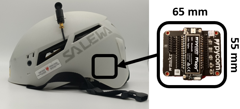 (b)
(b)
The input parameter of the helmet-mounted dipole is measured by a portable Vector Network Analyzer (MS2024A by Anritsu) when the volunteer is standing and lying over dry and wet terrains. Overall, despite some frequency shift between standing and fallen positions w.r.t. the nominal LoRa band, as predicted by the simulations (Fig. 4), the obtained reflection coefficient (Fig. 11) is always dB at the useful frequencies, and it is well comparable with the simulated value in Table IV. The maximum observed downward frequency shift is about MHz over all the conditions, so the helmet antenna must thus ensure a frequency bandwidth of at least MHz to cover the whole UHF LoRa band regardless of the wearer posture.
Measured - Commercial coronal dipole

The UAV is a DJI Phantom 3 Pro hosting a mm mm CP patch (Advantenna-p11 Keonn as before). The battery pack and the LoRa receiver are fixed at the landing gear of the UAV (Fig. 12).


(a)

(b)

(c) (d)
(d)
The RSS measurements are performed during a period of consecutive sunny days over an uncultivated field near Colle Romito†† GPS coordinates (41.551526, 12.567001). [Ardea, Lazio, Italy; Fig. 13(a)]. The field is flat [Fig. 13(b)] and covered by bushes. Thus, the test field can be considered dry ground. In the experiments, the UAV is driven at m/s approximate speed along both horizontal trajectories at fixed altitudes and vertical trajectories at a fixed radial distance from the user. The RSS in the dBm scale is estimated from the RSSI (received signal strength indicator) and from the SNR (signal-to-noise ratio) that are returned by the receiver, as [14]
| (8) |
where is in dBm scale, the RSSI is in dB scale, the SNR is in linear scale, and (dBm scale) is a constant parameter obtained from a single-point calibration [40] through the Anritsu MS2711A spectrum analyzer.
In the first test, the UAV takes off at a distance m from the volunteer and then flies up vertically up to m [Fig. 13(c)]. In the second test, the UAV flies horizontally at two fixed altitudes m, m} for distances m m [Fig. 13(d)]. During the flights, data packets are received overall.
The measured RSS profiles are reported in Fig. 14 and Fig. 15 and compared with the simulated ones for vertical and horizontal flights, respectively. Interestingly, the RSS is rather insensitive to the lying user’s particular position, and the modeling through a numerically evaluated equivalent gain is proven to be effective.
Overall, in spite of some differences, the measurements corroborate the phenomena derived by the numerical model in section IV (Fig. 7 and Fig. 9), even in the presence of the significant multi-path in the standing configuration. In detail, simulations overestimate the RSS of just dB on the vertical and horizontal paths shown in Fig. 14 and Fig. 15(a,b,d). Regarding Fig. 15(c), there are some differences with the simulations at the end of the profile, where the model underestimates the RSS. The measured profile follows the flat-earth two-ray model for m but, afterwards, it shows an intermediate behavior between the two-ray and the single-ray propagation. In this condition, the incident rays intercept the ground at grazing angles () so that slight surface irregularities are no longer negligible [42]. Moreover, the combined effect of the absorption by the low vegetation, scattering, and the earth elevation [Fig. 13(b)] can attenuate further the reflected field. The result is a weaker interference and, consequently, a lengthening of the link range, benefiting the target identification from long distances.
Vertical flights

(a) (b)
(b)

Horizontal flights

(a) (b)
(b)

(c) (d)
(d)
The Tx-Rx distance slightly affects also the time delay between the transmission and the reception of the packets. In the performed flights, the measured delay ranges between 820 ms (at the shortest helmet-UAV mutual distance) up to 1022 ms (upper bound distance) and is comparable with the values reported in [50]. By considering the typical packet transmission rate (roughly 1 packet every 3 s), the above delays will not cause any loss of the received packet sequence. Accordingly, the observed packet delivery ratio (PDR) in the experiments is of the order of 95% and nearly constant in all the cases. In more complex environments with non-flat grounds, the soft degradation of the LoRa signals will lead to reduced radio ranges with the corresponding decrease of the PDR [7, 14]. Concerning the implications on localization, the time delay could slightly raise the localization errors, especially if the target is moving. In SaR operations, however, the transmitter is mostly stationary since the wearer could be fallen or at most slowly moving within a confined area. The corresponding error in estimating the position of the target is therefore expected to be modest. Furthermore, the UAV will generally get closer and closer to the target during SaR procedures so that the time delay reduces, the PDR increases, and the estimation of the target position is progressively refined.
It is worth specifying that, due to hardware constraints and law regulations, the above experimental tests did not allow us to appreciate the complete communication range corresponding to the last received packet. For this purpose, the UAV should have flown up to a much longer horizontal distance ( m), thus exiting from the test area and overflying various obstacles (houses, roads, woods). Anyway, in past experiments [13], we placed a LoRa radio over an -m-high overpass while the other radio was kept inside a car that was driven away from the overpass. This arrangement, comparable with the helmet-UAV system, achieved communications up to km, in reasonable agreement with the numerical estimations.
VI Discussion and conclusion
The helmet-to-UAV communication over flat lands based on the LoRa protocol has been numerically characterized and corroborated by a preliminary experimental campaign. The UAV is theoretically capable of collecting the helmet signal up to km in a flat scenario even in the worst case (standing user, perfectly flat and wet terrain), and up to km in case of wet terrain and lying user when the UAV flies at an altitude of m. The RSS in the case of a lying user is robust concerning the position of the helmet on the ground, and it monotonically decreases with the Tx-Rx distance. Instead, the RSS with a standing user (e.g., a lost hiker wandering on a snowy land) experiences fluctuations that are sharper the wetter the terrain, due to the ground-bounce multi-path, especially near to the helmet’s wearer.
The basic model extension to a more complex radio propagation environment, including non-LoS links, can be quickly drawn if an equivalent log-distance PL model is available. For example, the authors recently modeled the LoRa propagation in snowy mountain fields, even when the transmitter is buried [14]. Burying the transmitter under m of snow adds an entry loss of about dB, which can be accounted for in the transmitter’s equivalent gain. Instead, the retrieved log-distance parameters for a transmitter placed on the snow were and dB, and these values are still approximately valid in the case of a lying user in a snowy plain. Hence, the path loss model and the eventual path-gain factor must be inserted appropriately in the proposed link budget.
It is worth considering that the communication could be more challenging or even forbidden in harsher conditions that excessively reduce the equivalent antenna gain, as, for instance, when the helmet is buried under more than 1 m of wet snow or deeply submerged by water (e.g., fallen into a river). In other cases, particular configurations of obstacles may highly raise the multi-path and the shadowing, as we observed when the target was on the bottom of a canyon while the UAV was flying outside it [51].
Finally, considering the model’s application to SaR operations, the lying user case is the most interesting because the user could be unconscious and even partially covered and, consequently, not detectable by a camera. The helmet wearer can be rescued through classic range-based localization algorithms like those mentioned in section I. Instead, in the case of a standing user, the interference fringes make applying the above localization methods more challenging [52]. Spatial fluctuations can be mitigated by lowering the UAV’s flying altitude. For instance, the RSS oscillations are confined between m far from the target for an altitude m. The fluctuations can also be reduced by placing the wearable antenna near the ground (e.g., on a boot). In any case, thanks to the local confinement of RSS fluctuations, the UAV can roughly estimate the target position from longer distances. Then, the UAV can approach the estimated location and, when the signal begins fluctuating, it could use the support of optical or thermal cameras to reach the user, who is standing and, likely, conscious. Hence, while the high-RSS fringes are produced by the reflection from the flat ground when the user is standing, the eventual low-RSS fringes are generated by the multi-path from non-flat terrains and will be observed for longer distances. Furthermore, the dynamic refinement of the position estimation while approaching the target allows also to contrast the packet’s loss caused by the harsh environment. Regardless of the target’s posture, the UAV could move along non-linear trajectories to speed up the search, as proposed in [53, 54], by dynamically accounting for the signal variations and the topology of the area. A swarm of multiple coordinated UAVs [55, 56] could also be deployed to provide data from different angles and distances to mitigate the multi-path effect.
References
- [1] “Emergency Support Function #9: SEARCH AND RESCUE”, N.H. Dept. of Fish and Game, Concord, New Hampshire State, USA, Rep. no ESF#9, 2006. Accessed: Feb. 12, 2021. [Online]. Available: https://prd.blogs.nh.gov/dos/hsem/wp-content/uploads/2015/03/ESF-9-Search-Rescue.pdf
- [2] W.-T. Chiu et al., “A survey of international urban search-and-rescue teams following the Ji Ji earthquake”, Disasters, vol. 26, no. 1, pp. 85-94, Dec. 2002.
- [3] B. Soule, B. Lefevre, E. Boutroy, V. Reynier, F. Roux, and J. Corneloup, Accidentology of Mountain Sports: Situation, Review & Diagnosis, Fondation Petzl, Crolles, France, 2014.
- [4] Avalanche Beacons operating at 457 kHz; Transmitter-receiver systems, ETSI EN 300 7181 V2.1.1, European Telecommunications Standards Institute, 2018. Accessed on: Feb. 12, 2021. [Online]. Available: https://www.etsi.org/deliver/etsi_en/300700_300799/30071801/02.01.00 _20/en_30071801v020100a.pdf
- [5] R9 Detector User Guide, RECCO Company, Liding, Sweden, 2009. Accessed: Feb. 12, 2021. [Online]. Available: https://usermanual.wiki /RECCO/A-
- [6] J. Bardyn, T. Melly, O. Seller and N. Sornin, “IoT: the era of LPWAN is starting now,” in Proc. 42nd Eur. Solid-State Circuits Conf., Lausanne, France, 2016, pp. 25-30.
- [7] J. Petajajarvi, K. Mikhaylov, A. Roivainen, T. Hanninen and M. Pettissalo, “On the coverage of LPWANs: range evaluation and channel attenuation model for LoRa technology,” in Proc. 14th Int. Conf. ITS Commun., Copenhagen, Denmark, 2015, pp. 55-59.
- [8] A. T. Nugraha, R. Wibowo, M. Suryanegara and N. Hayati, “An IoT-LoRa system for tracking a patient with a mental disorder: correlation between battery capacity and speed of movement,” in Proc. 7th Int. Conf. Compute. Commun. Eng., Kuala Lumpur, Malaysia, 2018, pp. 198-201.
- [9] J. Petajajarvi, K. Mikhaylov, M. Hemeleinen and J. Iinatti, “Evaluation of LoRa LPWAN technology for remote health and wellbeing monitoring,” in 10th Int. Symp. Med. Inf. Commun. Technol., Worcester, MA, USA, 2016, pp. 1-5.
- [10] L. Shi, H. Xu, W. Ji, B. Zhang, X. Sun and J. Li, “Real-time human activity recognition system based on capsule and LoRa,” in IEEE Sensors J., vol. 21, no. 1, pp. 667-677, Jan. 2021.
- [11] Z. Yuan, J. Jin, L. Sun, K. Chin and G. Muntean, “Ultra-reliable IoT communications with UAVs: A swarm use case,” in IEEE Commun. Mag., vol. 56, no. 12, pp. 90-96, Dec. 2018.
- [12] P. A. Catherwood, M. Little, D. Finlay and J. McLaughlin Obe, "Recovery of incapacitated commercial delivery drones using LPWAN technology," in IEEE Intell. Transp. Syst. Mag., vol. 12, no. 2, pp. 6-19, Apr. 2020.
- [13] G. M. Bianco, A. Mejia-Aguilar and G. Marrocco, “Performance evaluation of LoRa LPWAN technology for mountain search and rescue,” in Proc. 5th Int. Conf. Smart Sustain. Technol., Split, Croatia, 2020, pp. 1-4.
- [14] G. M. Bianco, R. Giuliano, G. Marrocco, F. Mazzenga and A. Mejia-Aguilar, “LoRa system for search and rescue: path-loss models and procedures in mountain scenarios,” IEEE Internet Things J., vol. 8, no. 3, pp. 1985-1999, Feb. 2021.
- [15] E. Sisinni, D. F. Carvalho and P. Ferrari, “Emergency communication in IoT scenarios by means of a transparent LoRaWAN enhancement,” in IEEE Internet of Things J., vol. 7, no. 10, pp. 10684-10694, Oct. 2020.
- [16] F. Gimenez, C. Zerbini and G. Riva, “Extending SMS service coverage in rural areas by using LoRa communication technology,” (in Spanish), IEEE Latin Amer. Trans., vol. 18, no. 2, pp. 214-222, Feb. 2020.
- [17] H. P. Tran, W.-S. Jung, T. Yoon, D.-S. Yoo and H. Oh, “A two-hop real-time LoRa protocol for industrial monitoring and control systems,” in IEEE Access, vol. 8, pp. 126239-126252, Jul. 2020, Art. no. 9136688.
- [18] K. Lin and T. Hao, "Experimental link quality analysis for LoRa-based wireless underground sensor networks," in IEEE Internet Things J., early access, Dec. 15 , 2020. doi: 10.1109/JIOT.2020.3044647.
- [19] M. S. Aslam et al., "Exploring multi-hop LoRa for green smart cities," IEEE Netw., vol. 34, no. 2, pp. 225-231, Mar. 2020.
- [20] T. V. Pham et al., "Proposed smart university model as a sustainable living lab for university digital transformation," in Proc. 5th Int. Conf. Green Technol. Sustain. Develop., Ho Chi Minh City, Vietnam, Nov. 2020, pp. 472-479.
- [21] J. H. Lee and R. M. Buehrer, “Fundamentals of received signal strength-based position location,” in Handbook of Position Location: Theory, Practice, and Advances, 1st ed, Hoboken, NJ, USA, John Wiley and Sons, 2012, ch.11, pp. 359-395.
- [22] G. M. Bianco, R. Giuliano, F. Mazzenga and G. Marrocco, "Multi-slope path loss and position estimation with grid search and experimental results," IEEE Trans. Signal Inf. Process. Netw., vol. 7, pp. 551-561, 2021
- [23] M. R. Gholami, R. M. Vaghefi, and E. G. Stram, “RSS-based sensor localization in the presence of unknown channel parameters,” IEEE Trans. Signal Process., vol. 61, no. 15, pp. 3752–3759, Aug. 2013.
- [24] X. Li, “RSS-based location estimation with unknown pathloss model,” IEEE Trans. Wireless Commun., vol. 5, no. 12, pp. 3626–3633, Dec. 2006.
- [25] Y. Saita, T. Ito, N. Michishita and H. Morishita, “Low-frequency inverted-F antenna on hemispherical ground plane,” in Proc. Int. Symp. Antennas Propag. Conf., Kaohsiung, Taiwan, 2014, pp. 183-184.
- [26] D. Kitching and F. Lalezari, “Low profile helmet mount GPS antenna,” in Proc. Conf. Tactical Commun., Fort Wayne, IN, USA, 1990, pp. 661-702.
- [27] N. Nishiyama, N. Michishita and H. Morishita, “SAR reduction of helmet antenna composed of folded dipole with slit-loaded ring,” in Proc. Int. Symp. Antennas Propag., Hobart, Australia, 2015, pp. 1-2.
- [28] N. Nishiyama, N. Michishita and H. Morishita, “Low-frequency inverted-F antenna on annular ground plane,” in Proc. IEEE MTT-S Int. Microw. Workshop Series RF Wireless Technol. Biomed. Healthcare Appl., Taipei, Taiwan, 2015, pp. 143-144.
- [29] J.-Y. Park, H.-K. Ryu and J.-M. Woo, “Helmet installed antenna using a half-wavelength circular loop antenna,” in Proc. IEEE Antennas Propag. Soc. Int. Symp., Honolulu, HI, USA, 2007, pp. 4176-4179.
- [30] A. Kachroo et al., "Unmanned aerial vehicle-to-wearables (UAV2W) indoor radio propagation channel measurements and modeling," in IEEE Access, vol. 7, pp. 73741-73750, May 2019.
- [31] T. Ameloot, P. Van Torre and H. Rogier, “LoRa base-station-to-body communication with SIMO front-to-back diversity”, IEEE Trans. Antennas Propag., vol. 69, no. 1, pp. 397-405, Jan. 2021.
- [32] S. Dumanli, L. Sayer, E. Mellios, X. Fafoutis and G. S. Hilton, “Off-body antenna wireless performance evaluation in a residential environment”, IEEE Trans. Antennas Propag., vol. 65, no. 11, pp. 6076-6084, Nov. 2017.
- [33] T. O. Olasupo, “Wireless communication modeling for the deployment of tiny IoT devices in rocky and mountainous environments,” IEEE Sensors Lett., vol. 3, no. 7, pp. 1–4, Jul. 2019
- [34] M. Simunek, F. P. Fontan and P. Pechac, “The UAV low elevation propagation channel in urban areas: statistical analysis and time-series generator”, IEEE Trans. Antennas Propag., vol. 61, no. 7, pp. 3850-3858, Jul. 2013.
- [35] Z. Cui et al., “Low-altitude UAV air-ground propagation channel measurement and analysis in a suburban environment at 3.9 GHz,” IET Microw., Antennas Propag., vol. 13, no. 9, pp. 1503-1508, Jul. 2019.
- [36] N. E.-D. Safwat, F. Newagy and I. M. Hafez, “Air-to-ground channel model for UAVs in dense urban environments,” IET Microw., Antennas Propag., vol. 14, no. 6, pp. 1016-1021, Apr. 2020.
- [37] K. Mikhaylov, J. Petajajarvi and T. Hanninen, “Analysis of capacity and scalability of the LoRa low power wide area network technology,” in 22nd Eur. Wireless Conf., Oulu, Finland, 2016, pp. 1-6.
- [38] Electrical characteristics of the surface of the Earth, ITU-R P.527-4, International Telecommunication Union Radiocommunication Sector, 2017. Accessed: Feb. 12, 2021. [Online]. Available: https://www.itu.int/rec/R-REC-P.527-4-201706-I/en
- [39] A. A. Khuwaja, Y. Chen, N. Zhao, M. Alouini and P. Dobbins, “A survey of channel modeling for UAV communications,” IEEE Commun. Surv. Tut., vol. 20, no. 4, pp. 2804-2821, doi: 10.1109/COMST.2018.2856587.
- [40] SX1272/73 Datasheet, Semtech Corporation, Camarillo, CA, USA, 2017. Accessed: Feb. 12, 2021. [Online]. Available: https://www.mouser.com/datasheet/2/761/sx1272-1277619.pdf
- [41] M. Bor and U. Roedig, “LoRa transmission parameter selection,” in Proc. 13th Int. Conf. Distrib. Comput. Sensor Syst., Ottawa, Canada, 2017, pp. 27-34.
- [42] R. E. Collin, “Radio-Wave Propagation”, in Antennas and Radiowave Propagation, New York, NY, USA, Mc-Graw Hill, 1985, ch. 6, sec. 1, pp. 339-349.
- [43] G. Casati et al., “The interrogation footprint of RFID-UAV: electromagnetic modeling and experimentations,” IEEE J. Radio Freq. Identification, vol. 1, no. 2, pp. 155-162, June 2017.
- [44] G. Marrocco, E. Di Giampaolo and R. Aliberti, “Estimation of UHF RFID reading regions in real environments,” IEEE Antennas Propag. Mag., vol. 51, no. 6, pp. 44-57, Dec. 2009.
- [45] IEEE Recommended Practice for Determining the Peak Spatial-Average Specific Absorption Rate (SAR) in the Human Head from Wireless Communications Devices: Measurement Techniques, IEEE 1528-2013, IEEE Standards Association, Sept. 2013. [Online]. Available: https://standards.ieee.org/standard/1528-2013.html
- [46] Y. H. Kim, S. W. Chan, J. Ahn and S. H. Cho, “Studies of the variation in the dielectric constant and unique behaviors with changes in the foaming ratio of the microcellular foaming process”, in Polym.-Plastics Technol. Eng., vol. 50, no. 8, pp. 762-767, June 2011.
- [47] “Safe operation of drones in Europe”, European Union Aviation Safety Agency, April 2018. Accessed: Nov. 5, 2020. [Online]. Available: https://www.easa.europa.eu/sites/default/files/dfu/217603_EASA_ DRONES_LEAFLET%20%28002%29_final.pdf
- [48] M. Saelens, J. Hoebeke, A. Shahid and E. De Poorter, “Impact of EU duty cycle and transmission power limitations for sub-GHz LPWAN SRDs: an overview and future challenges,” in EURASIP J. Wireless Commun. Netw., vol. 2019, Sept. 2019, Art. no. 219, doi: 10.1186/s13638-019-1502-5.
- [49] LoRa (868MHz/915MHz) & Sigfox Antenna Kit, Pycom Company, Guildford, U.K., 2017. Accessed on: Feb. 12, 2021. [Online]. Available: https://pycom.io/product/lora-868mhz-915mhz-sigfox-antenna-kit/
- [50] E. D. Widianto, M. S. M. Pakpahan, A. A. Faizal and R. Septiana, "LoRa QoS performance analysis on various spreading factor in Indonesia," Int. Symp. Electron. Smart Devices, 23-24 Oct. 2018, Bandung, Indonesia, pp. 1-5.
- [51] A. Mejia-Aguilar, G. M. Bianco, G. Marrocco, A. Voegele, M. van Veelen and G. Strapazzon, “In-situ and proximal sensing techniques for monitoring natural hazards to mitigate risk in tourism activities: A case study in the Geoparc Bletterbach, Italy”, IEEE Int. Geosci. Remote Sens. Symp., Brussels, Belgium, 11-16 July 2021.
- [52] R. J. R. Thompson, E. Cetin, and A. G. Dempster, “Unknown source localization using RSS in open areas in the presence of ground reflections,” in Proc. 2012 IEEE/ION Position, Location Navigation Symp., Myrtle Beach, SC, USA, Apr. 2012, pp. 1018–1027.
- [53] A. Buffi, A. Motroni, P. Nepa, B. Tellini and R. Cioni, "A SAR-based measurement method for passive-tag positioning with a flying UHF-RFID reader," IEEE Trans. Instrum. Meas., vol. 68, no. 3, pp. 845-853, Mar. 2019.
- [54] S. A. A. Shahidian and H. Soltanizadeh, “Optimal trajectories for two UAVs in localization of multiple RF sources,” Trans. Inst. Meas. Control, vol. 38, no. 8, pp. 908-916, Aug. 2016.
- [55] H. Sallouha, M. M. Azari, A. Chiumento and S. Pollin, "Aerial anchors positioning for reliable RSS-based outdoor localization in urban environments," IEEE Wireless Commun. Lett., vol. 7, no. 3, pp. 376-379, June 2018.
- [56] Y.-J. Chen, D.-K. Chang and C. Zhang, "Autonomous tracking using a swarm of UAVs: a constrained multi-agent reinforcement learning approach," IEEE Trans. Veh. Technol., vol. 69, no. 11, pp. 13702-13717, Nov. 2020