A Review of Millimeter Wave Device-based Localization and Device-free Sensing
Technologies and Applications
Abstract
The commercial availability of low-cost millimeter-wave (mmWave) communication and radar devices is starting to improve the adoption of such technologies in consumer markets, paving the way for large-scale and dense deployments in fifth-generation (5G)-and-beyond as well as 6G networks. At the same time, pervasive mmWave access will enable device localization and device-free sensing with unprecedented accuracy, especially with respect to sub-6 GHz commercial-grade devices.
This paper surveys the state of the art in device-based localization and device-free sensing using mmWave communication and radar devices, with a focus on indoor deployments. We overview key concepts about mmWave signal propagation and system design, detailing approaches, algorithms and applications for mmWave localization and sensing. Several dimensions are considered, including the main objectives, techniques, and performance of each work, whether they reached an implementation stage, and which hardware platforms or software tools were used.
We analyze theoretical (including signal processing and machine learning), technological, and implementation (hardware and prototyping) aspects, exposing under-performing or missing techniques and items towards enabling a highly effective sensing of human parameters, such as position, movement, activity and vital signs. Among many interesting findings, we observe that device-based localization systems would greatly benefit from commercial-grade hardware that exposes channel state information, as well as from a better integration between standard-compliant mmWave initial access and localization algorithms, especially with multiple access points (APs). Moreover, more advanced algorithms requiring zero-initial knowledge of the environment would greatly help improve the adoption of mmWave simultaneous localization and mapping (SLAM). Machine learning (ML)-based algorithms are gaining momentum, but still require the collection of extensive training datasets, and do not yet generalize to any indoor environment, limiting their applicability.
Device-free (i.e., radar-based) sensing systems still have to be improved in terms of: improved accuracy in the detection of vital signs (respiration and heart rate) and enhanced robustness/generalization capabilities across different environments; moreover, improved support is needed for the tracking of multiple users, and for the automatic creation of radar networks to enable large-scale sensing applications. Finally, integrated systems performing joint communications and sensing are still in their infancy: theoretical and practical advancements are required to add sensing functionalities to mmWave-based channel access protocols based on orthogonal frequency-division multiplexing (OFDM) and multi-antenna technologies.
Index Terms:
Millimeter waves; propagation characteristics; channel models; communications; localization; sensing; radar; practical constraints;I Introduction
Millimeter-wave (mmWave) communications in the 28–300 GHz band are looked at with great interest, as they may be able to quench –at least temporarily– the ever-increasing bandwidth requirements of such applications as massive Internet of things (IoT), virtual/augmented reality, mobile cloud services and ubiquitous ultra-high definition multimedia streaming [1, 2, 3]. This would cover the shortcomings of sub-6 GHz technologies such as WiFi and fourth-generation (4G) cellular networks, which currently cannot support the massive bandwidth and number of users the above applications imply.
The potential of mmWave technology, however, is not limited to higher-rate communications: rather, mmWave devices can become a proxy for high-resolution device-based localization as well as device-free sensing. These capabilities follow from the physics of mmWave propagation. First, the shorter wavelength of mmWaves (compared to sub-6 GHz signals) enables accurate location estimates and lower location error bounds [4, 5]. Second, mmWaves have well-known and peculiar propagation characteristics [6, 7] which yield higher spatial scanning resolution. For example, mmWaves propagate quasi-optically, meaning that a line-of-sight (LoS) multipath component (MPC) is predominant over non-line-of-sight (NLoS) contributions to the received signal [8]. Scattering also has a limited impact off typical non-rough reflecting surfaces such as walls, furniture, metal plates as well as glass layers [9], [10].
Another consequence of mmWave propagation is that mmWave signals undergo much higher path loss with respect to microwaves. To compensate for this attenuation, and still enable long-reach wireless links, mmWave devices resort to large or massive antenna arrays. Via beamforming, they can focus their transmitted energy towards a confined portion of the 3D space, and thus achieve greater directionality. While this requires specific protocols for initial access [11, 12, 13] and beam training such as the IEEE 802.11ad [14, 15] and 802.11ay [16, 17] standards, it also means that a reduced amount of power is typically directed towards secondary multipath components. In addition with the quasi-optical propagation patterns discussed above, the main consequence is that the received angular spectrum of a mmWave signal is sparse: in typical conditions, one can identify one LoS MPC along with a number of NLoS MPCs corresponding to signal reflections off the surrounding environment. The above features of mmWave communications have significant implications for localization and sensing [18]. For example, being able to separate MPCs in the angular domain enables angle-based localization schemes that are not normally used in sub-6 GHz systems due to limited angular resolution when using small antenna arrays. Fingerprinting-based algorithms can also be enhanced by incorporating angle-based features to improve location discrimination. From the point of view of device-free sensing, mmWave propagation also implies typically clearer reflections off sensed targets and parts thereof. For example, a) quasi-optical mmWave propagation along with b) the large mmWave bandwidth available at typical mmWave radar frequencies respectively imply that reflections off targets are usually separate in the a) angle and b) time domains. This makes it possible to measure features that point to each reflection’s movement velocity (e.g., the Doppler shift) and use this data to precisely localize and identify different targets.
In this paper, we focus on indoor mmWave device-based localization and device-free sensing, and provide a comprehensive review of approaches, technologies, schemes and algorithms to estimate a device or object’s location in an indoor environment. The objective of our survey is to shed light on indoor applications of localization and sensing using mmWave signals. Location information can be extremely useful in different indoor setups [19, 20]. For example, in factories and industrial environments, location information can be exploited to enhance ultra-reliable low-latency communications (URLLC) for industrial IoT and smart manufacturing [21, 22]. Accurate localization and sensing can benefit healthcare scenarios for patient tracking and lifesign/behavior monitoring, help people navigate in indoor areas, provide trajectory suggestions through relevant waypoints in museums, malls, and company headquarters, as well as support mission-critical applications such as disaster relief and indoor security. Location systems are also crucial for network performance optimization. Accurate location information can support the fast alignment of transmit and receive antenna arrays, optimize the association between clients and access points (APs), and prevent blockage of high-power LoS paths via predictive handovers to provide seamless coverage. This can result in low-latency communications as needed for augmented reality, virtual reality, and tactile Internet applications.
In the following, we start with an overview that touches on mmWave signal structure and propagation characteristics that make this domain unique with respect to other radio communication and sensing technologies. We consider practical constraints that define the applicability of algorithms and processing schemes to mmWave devices operating indoors. We then delve into a detailed description of device-based indoor localization algorithms, explaining the main localization techniques employed in the literature, and how they are practically implemented in real mmWave hardware whenever available. For device-free sensing, we list a number of relevant applications and technologies that leverage mmWave hardware and signals to detect, localize and track targets indoors, as well as to specifically identify features related to sub-sections of a target (e.g., a part of the human body). Because these device-free approaches are mainly based on mmWave radar devices, we will briefly discuss how mmWave radar bands are being standardized for different applications.
I-A Differences with respect to previous surveys
Localization and sensing are topics of great interest for both current and future-generation wireless communication system engineering. The research on these topics has proceeded at a steady pace, considering aspects as diverse as localization techniques, heterogeneous technologies, different scenarios, and different kinds interactions between the device to be localized and the location server, among others. Several surveys cover these aspects, typically for sub-6 GHz technologies. For example, Zafari et al. [23] and Geok et al. [24] focus on localization techniques for wireless systems in general, and cover heterogeneous technologies. These works only tangentially consider mmWaves, and instead survey geometric and signal processing-based localization methods for sub-6 GHz systems. Ngamakeur et al. [25] delve into device-free sensing of different human signatures using sub-6 GHz technologies indoors. Here, the focus is on the localization, tracking and identification of multiple subjects using Wi-Fi and other kinds of wireless sensors.
By leveraging similar technologies, Singh et al. [26] consider techniques and algorithms to localize IoT devices indoors. In this case, the focus of the survey is on a specific source of location information (received WiFi signal strength fingerprints) and on how machine learning works when applied to such datasets. By expanding into the concept of smart world, the work in [27] also surveys how sub-6 GHz technologies can help improve a variety of services via data collection and system automation using active and passive sensing techniques. Finally, the work in [28] touches on aspects related to the modeling and estimation of wireless channels in fifth-generation (5G) cellular systems. While the work touches on localization, the covered techniques apply to outdoor cellular systems, and can thus leverage the density and much higher computational power of their hardware.
Unlike our survey, none of the above works targets millimeter wave device-based and device-free indoor localization. This area is characterized by several interesting research works to date, but remains a very hot topic due to the inception of mmWave coverage for future 5G-and-beyond networks as well as wireless (indoor) local-area networks. The objective of our survey is to cover the most significant work in this area, while giving a comprehensive view of unsolved challenges and open research avenues.
Note that, in our survey, we are not seeking an analysis of the limits of mmWave localization and sensing technology based on purely theoretical arguments, or an operational description of well-known geometric localization algorithms, or even a coverage of the integration between mmWave communications and 5G, beyond-5G, and future 6G networks. These are related yet tangential topics for which we rather refer the interested reader to one of the several excellent surveys that touch on these aspects, e.g., [19, 18, 28, 29, 30, 22, 31, 32, 33, 34].
I-B Outline and organization of the manuscript
The remainder of this paper expresses three purposes: to cover the characteristics of mmWave propagation and communication/sensing hardware that impacts localization and sensing performance, including standardization efforts (Sections II through IV); to detail the state of the art in device-based mmWave localization (Section V) and in device-free mmWave sensing (Section VI); and finally to discuss our findings, discuss promising research avenues, and draw concluding remarks (Sections VII and VIII).
In particular, Sections V and VI constitute the core of our technological survey. Section V discusses device-based localization algorithms for indoor environments, whereas Section VI presents several approaches for radar-based device-free localization. Each section is organized to first present the section topic, and then to add progressively more details related to the typical techniques appropriate for each section, the hardware typically used in testbeds, and the description of each surveyed approach. We also include summary tables to help the reader navigate the contents and extract key information. Both Sections V and VI end with a summary of the most relevant aspects and findings.
II Influence of mmWave channels
II-A Impact of mmWave frequencies on propagation conditions
The propagation of a wave through any medium depends on its frequency: this basic property helps us predict the behavior of the channel for diffeangularrent carrier frequencies. When it comes to mmWaves, considering the Friis equation under the assumption that the antenna gain at both link ends is frequency-independent (by reducing the antenna aperture), the free space path loss increases with the square of the carrier frequency . On the contrary, assuming a constant physical area at both the transmitter (TX) and the receiver (RX), the antenna gains increase on both sides, and thus the overall path loss decreases quadratically with increasing frequency [35]. Specular reflections for dielelectric halfspaces (e.g., ground reflections) depend on frequency as long as the dielectric constant is itself a function of frequency. For reflections at a dielectric layer (e.g., building walls) the specular reflections depend on the electrical thickness of the wall, which in turn is also a function of frequency. Interestingly, we have no evidence that the reflection coefficient varies with frequency, although the transmission power decreases uniformly with increasing frequency due to the skin effect in lossy media [36].
Two effects that have gained spotlight with the increased interest in the mmWave band are diffraction and diffuse scattering. The former reduces noticeably at high frequencies, and larger objects lead to “sharp” shadows. The latter effect is more significant as the surface roughness becomes comparable to mmWave wavelengths. As the surface roughness increases, the objects behave like a Lambertian radiator, which scatters the radiation. Foliage has a similar effect as scattering; with the decreasing wavelength relative to the size of the leaves, we observe more diffused scattering and less penetration. Another factor is atmospheric attenuation due to fog or rain[37] and may affect the mmWave frequencies in case of extreme weather.
Channel models used for localization need to account for the above mentioned phenomena, and are often based on ray tracing or cluster-based modeling with some geometry-based stochastic channel model (GSCM) [38, 39, 40]. Moreover, for ray tracing approaches, high-resolution environment information is needed to account for such surface roughness, as different materials have different properties (e.g., glass windows vs. concrete walls). These effects also depend on the environment: the high concrete walls and glass surfaces of the urban areas lead to different propagation conditions, compared to the greener suburban areas with, e.g., stucco exteriors and shorter walls.
II-B Measurement techniques and results
To model the properties of a channel, we need to perform the measurements for different propagation scenarios. A channel sounder, that helps to measure these properties is not only an expensive piece of equipment but as we move towards higher frequencies, the susceptibility to phase noise as well as antenna spacing errors start to increase. Similarly, the cost and energy consumption of up/down-conversion chains, in particular of the front-end mixed signal circuitry in analog-to-digital and digital-to-analog converters (ADCs/DACs) as well as power amplifiers (PAs) becomes of paramount importance. For up-to-Gbit/s sampling rates (as often required by best-in-class channel sounding), 12-15 bit resolution is required. To penetrate larger distances (and thus to maximize the forward link gain), PAs typically need to operate with 6-10 dB backoff power efficiency and need to be continuously driven close to their 1 dB compression point limits.
Consequently, the channel sounders used often for measurements at high frequencies use omnidirectional antennas [41] or if directional [42], then the angular resolution is not taken into account. Directionality is achieved by mechanically rotating horn antennas in most cases and the angular resolution corresponds to the beamwidth, e.g., [43, 44, 45]. For indoor measurement scenarios, the directional information though can be enhanced by using switched antenna arrays along with super-resolution algorithms like space-alternating generalized expectation maximization (SAGE) [46] and RIMAX [47]. It is possible to use electronically-switched horn arrays [48] as well, which additionally lets us evaluate the MPC and intra-cluster information.
II-B1 Key outdoor results
When it comes to outdoor measurements, path loss is a key parameter. For channel modelling, we need to measure the pathloss coefficient, its mean and its variance. The pathloss coefficient for mmWave frequencies is close to that of microwaves, i.e., often there is no strong frequency dependence beyond the dependence of free-space path loss [49]. In LoS scenarios, the path loss coefficient lies between 1.6-2.1 (2 for pure free-space propagation) and in NLoS scenarios the value increases to 2.5 and 5 (e.g., [43, 44, 50]).
On the other hand, the variance of the path loss around the distance-dependent mean is higher at mmWave frequencies, which in turn increases the probability of outage [51]. The standard deviation as well is strongly dependent on the distance and its values increases from 5-10 dB to more than 20 dB as the distance increases from 30 m to 200 m [50]. This is due to the variation in power levels caused by location and orientation of a street in an urban macro cell [52] and not due to shadowing as one may expect.
Another parameter important for channel modelling is the root mean square (RMS) delay spread. But it changes with frequency and thus it may not be the best parameter to model the delay dispersion. Instead, delay windows may be a better alternative as they define the time interval containing part of the energy of power-delay profile (PDP). Delay spreads in an outdoor environment are measured or simulated by ray tracing [43, 44, 45, 53]. Beamforming can help with minimizing the delay spread [54]. The type of beamforming to be used depends on the angular dispersion properties. Angular spreads measured at the base station (BS) are more accurate than those measured at the user equipment (UE) as the ray tracers used often do not include scattering objects such as street signs, parked cars, etc. in their geographic database [50, 55]. As observed in [44, 56], the RMS angular spread at the BS is of the order of 10∘ with one cluster only while at the UE, the angular spreads are in the range 30-70∘ [43, 44, 56, 57].
More information related to fixed wireless scenarios can be found in [58].
| Parameter | mmWave Channel Models | |||||
| 3GPP [59] / ITU-R [60] | COST IRACON [61] | METIS [53] | QuaDRiGa [62] | NYUSIM [63] | ||
| (GHz) | 6 | 2.6 | 0.45-63 | 5.4 | 28 | |
| Type | 2D GSCM | GSCM | 3D Map-based & GSCM | 3D GSCM | TCSL | |
| K- factor | 7 | N/A | 7.9 | -1.6 | N/A | |
| 4 | N/A | 6 | 2.7 | N/A | ||
| Delay Spread | -7.7 | 1.07 | -7.42 | -7.22 | 2.7 | |
| 0.18 | 0.93 | 0.32 | 0.08 | 1.4 | ||
| AOA Spread | 1.62 | 3.94 | 1.65 | 1.67 | 19.3 | |
| 0.22 | 3.91 | 0.47 | 0.15 | 14.5 | ||
| AOD Spread | 1.60 | 0.71 | 1.64 | 1.54 | 23.5 | |
| 0.18 | 0.59 | 0.43 | 0.1 | 16.0 | ||
| ZOA Spread | 1.22 | 3.73 | 1.28 | 1.61 | 7.4 | |
| 0.297 | 2.11 | 0.26 | 0.07 | 3.8 | ||
| ZOD Spread | N/A | 1.95 | 1.31 | 1.17 | -7.3 | |
| N/A | 1.80 | 0.31 | 0.07 | 3.8 | ||
| XPR (dB) | 11 | 15.59 | 29 | 13 | N/A | |
| 4 | 10.39 | 6.5 | 1.6 | N/A | ||
| Shadow fading | 47.9 | N/A | N/A | 36.1 | N/A | |
| 3 | N/A | 3 | 1.6 | N/A | ||
II-B2 Key indoor results
Measurements for indoor environments have picked up in recent years as we look at localization applications for 5G. The results are often from office and industrial environments, where different material densities can be studied. The path loss coefficient in this case ranges from 1.2-2 in LoS to 2-3 in NLoS scenarios [64, 65]. The frequency dependence of the path loss is more significant for indoor than outdoors, with was observed in [66]. Overall though, the values are closer to those at sub-6 GHz, with an increased probability of outage. Path loss in some cases is shown to follow a dual-slope model and is the same for both mmWave and sub-6 GHz. The floating intercept model is another alternative used in Third-generation partnership project (3GPP) standards for indoor modelling at high frequencies. Human blockage can cause upto 10-20dB attenuation regardless of one or two people[67] and similar values in case of trucks in outdoor scenarios[68]. In [69], fast Fourier transform (FFT) based beamforming is used in conjunction with a very large virtual array (252525 elements). It highlights the scattering caused by small objects specifically in NLoS case and the importance of small scale characterization. Further, it is shown that the indoor environment leads to enhanced diffused MPC energy.
Delay spread measured in office scenarios is usually less than 5 ns in LoS conditions, and 10–20 ns in NLoS conditions [70, 71, 72, 65, 73]. Though these measurements were limited to under 100 GHz, recently [74] performed measurements at 142 GHz and observed delay spread values of 3 ns in LoS and 9 ns for NLoS. Further, the observed channels are much sparser at frequencies over 100 GHz and we notice higher partition loss compared to 28 GHz. It is worth noting for indoor measurements, the number of MPCs is higher with more clusters than measured for outdoor with rotating horn antennas [75]. Here the angular spreads are often measured for clusters, with the intra-cluster azimuth and elevation angles are described as having a Laplacian distribution with a spread of 5∘ [76].
II-C Models for mmWave channels
Because mmWave propagation channels differ from microwave channels, we need to redefine or rather add certain parameters for mmWave channel modeling. As mentioned in [58], mmWave channels require 3D modeling of azimuth as well as elevation spreads, inclusion of temporal/spatial/frequency consistency and multipath cluster based modeling. These have further impact when we consider positioning and localization. Prevalent models for mmWave are GSCMs that imitate the propagation environment with stochastic processes, and create a 3D map. To correctly reproduce the wireless environment, parameter values need to be extracted from the channel impulse response of real time measurements done using a channel sounder. An extensive review of propagation chacteristics at mmWave frequencies is available in [77], which also provides a summary of channel sounder measurements and relevant channel models. The 3GPP defined different environments for mmWave channel modeling, these include Urban Macro, Urban Micro, Indoor Office and Rural Macro. Several outdoor and indoor measurements are available, but for this paper we compare large-scale parameter values for an indoor office scenario listed in Table I.
Prominent channel models have been developed for the above mentioned scenarios based on measurements done in each of them. Some key results have already been discussed, but we also observe that cluster-based multipath channel components have been modelled, in order to specifically account for an indoor office environment. Also, as can be seen from the table, the angular spread is no longer limited to the azimuth plane.
II-C1 Static vs. dynamic modeling
Due to the high frequency and thus higher path loss, there is significant deterioration when the UE is stationary and more so when the UE is moving or is in a high movement zone and transitions from a LoS to NLoS scenario. This requires the dynamic modeling of the communication channel, as the moving objects in the vicinity also act as random blocking obstacles. The BS needs to transmit training beams more frequently so as to update the angle of departure (AoD)/angle of arrival (AoA) estimates, since the location of UE changes over time, and slight errors in the orientation of the beams can lead to significant performance loss [78]. So far, we have considered a fixed BS and slow moving UE, but with 5G and vehicle-to-everything (V2X) communications we expect high mobility scenarios[79]. Most mmWave channel models are still defined only for a fixed BS, but have added support for dynamic modeling scenarios for V2X.
II-C2 Blockage
mmWaves cannot penetrate obstacles such as human bodies, walls, foliage, etc. Thus, these blockage sources need to be modelled in the link budget itself. One such characterization study is found in [80], which measured power loss (in dB) when 70-GHz mmWave signals propagate through a brick wall, a PC monitor, and book shelves. Blockage does not affect just the total received power but also the angle or power of multipath signal components, due to varying sizes, positions and directions of the blocking object/human. Localizing the position of the UE with respect to these blockage sources becomes onerous, especially in a dynamic setting.
II-C3 Spatial consistency and clusters
A new, previously unexplored requirement was added to 3GPP Release 14 [59]. When mmWave communications take place through narrow antenna radiation beams, the channel characteristics become highly correlated, especially when two UEs are close and see the same BS. Also, for applications related to V2X communications, it is paramount that the channel evolves smoothly without discontinuities during mobility [81].
II-C4 Polarization
The radiation pattern of each antenna element of an array extends over both the azimuthal plane and the elevation plane, and should be separately modelled for directional performance gains. Moreover, as we consider indoor scenarios with higher number of reflections, the polarization properties of the multipath components also come into play.
II-C5 Large bandwidth and large antenna arrays
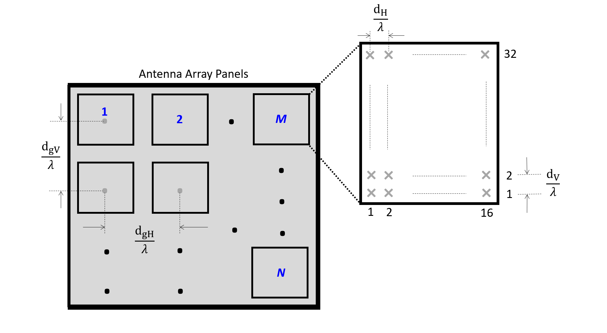
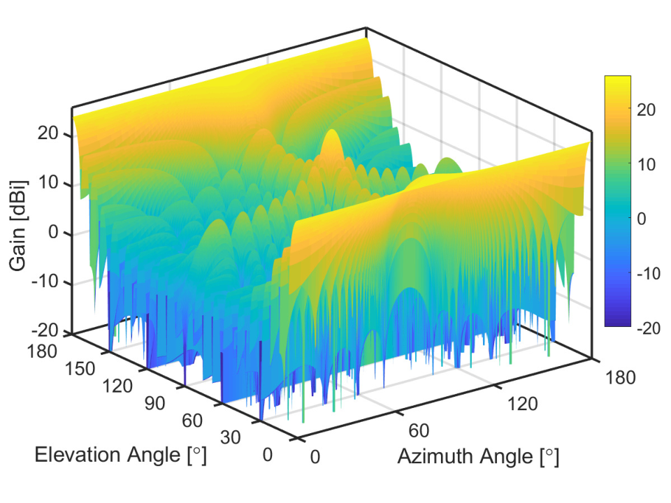
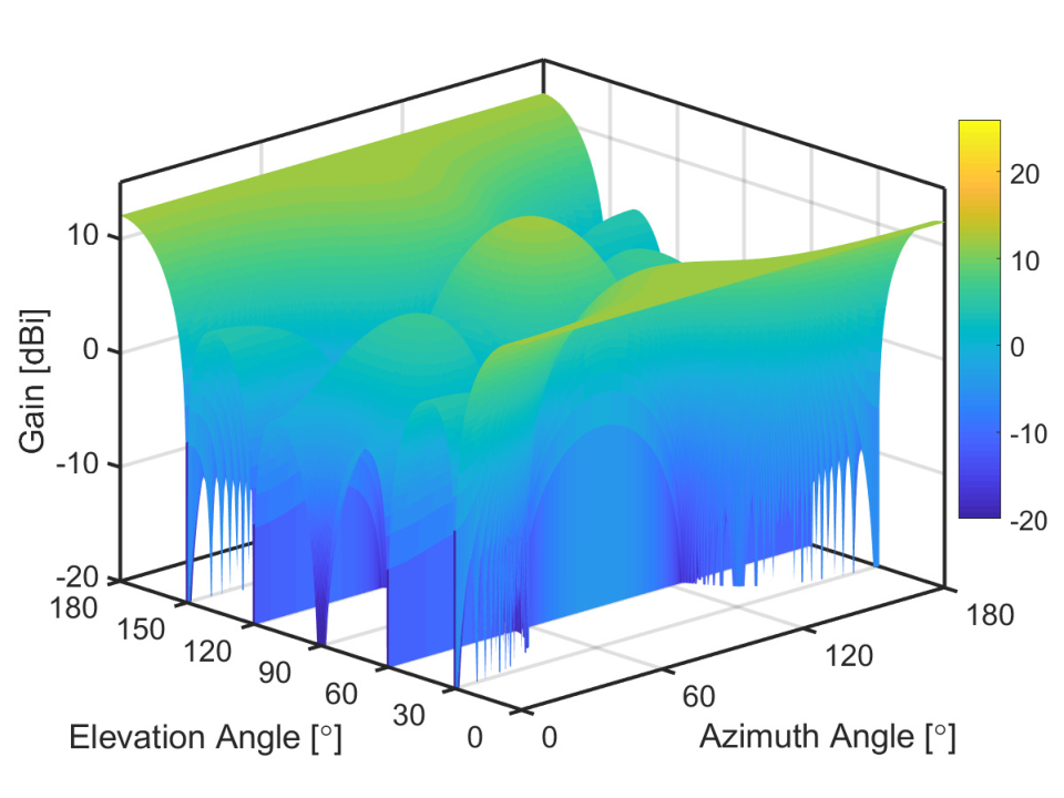
Antenna arrays that are larger in size and also massive in the number of antenna elements are needed at mmWave, thus high resolution channel modeling includes propagation patterns both in the angular domain and in the delay domain. Massive MIMO channel models[82] have previously not considered these exceptions but at mmWave, accurately modeling of the higher number of multipath components and their AoA/AoD is paramount. Antenna elements in azimuth and elevation plane both need to be evaluated to consider all possible array structures (planar array, rectangular array, cylindrical array). Fig. 2 depicts an antenna array panel used for 3GPP/International telecommunication union – radiocommunication Sector (ITU-R) antenna modeling [59, 60]. Figs. 3 and 4 show the BS and UE array radiation pattern based on parameters as defined in [59, Table 7.3-1, page 22].
II-D Summary
The mmWave channel when considered for indoor applications differs from the microwave channel in key aspects such as free space path loss, diffraction, and penetration loss with respect to different surfaces. This required the need for different measurements to be done for channel characterization. Some key results are presented in Section II-B. Path loss equations and penetration loss for indoor scenarios can be found in [59, Tables 7.4.1-1 and 7.4.3-1]. Various channel models have been developed, these include those by 3GPP [59], ITU-R [60], METIS [53], MiWEBA [45], Fraunhofer HHI’s QuaDRiGa [62], COST2100 [83], NYUSIM [84] which still has ongoing measurements for indoor scenarios. The channel models are all GSCM-based with added cluster based modeling. Small-scale parameter values are further available when considering indoor scenarios found in the documentations mentioned for corresponding models.
Several measurements have been done in the mmWave band for outdoor (urban macro and urban micro) scenarios but the indoor measurements are limited to the sub-6 Ghz band for the channel models developed with the exception of [85], where the authors propose an extension for an indoor channel model based on extensive measurements carried out at 28 and 140 GHz. We observe that indoor channel models are an extension of outdoor ones, and can be adapted easily based on the delay and angular spreads of any environment, as well as by adapting path loss modeling.
III Implications of beamforming architectures for mmWave localization
It is a common misconception that for higher frequencies the free space propagation loss is higher. As explained in [86, 87], for given aperture area of the antennas used, shorter wavelengths propagate farther due to the narrow directive beams. This is further verified in [88] with a patch antenna operated at 3 GHz and an antenna array operated at 30 GHz of the same physical size. We observe equal amounts of propagation loss irrespective of the operating frequency. Thus, mmWave frequencies enable the use of antenna arrays that produce highly directional beams which lead to large array gains. This can be observed from Fig. 5, which shows not only the increase in array size with respect to the beam penetration distance, but also how the larger array size increases the coverage area [35].

III-A Analog beamforming
Analog beamforming, sometimes also referred to as beam steering, is done by connecting a single radio frequency (RF) chain to a string of phase shifters that are both energy- and cost- efficient. Each phase shifter multiplies its input by , where , is the number of bits, and is used to control the phase shifters. Most commonly, codebook-based schemes are used to steer the beams in the direction of the UE /receiver. At the receiver, the received signal strength indicator (RSSI) is the most commonly used parameter to estimate the direction of arrival and delay, and thus localize the device. However, phase shifters have a constant amplitude constraint and limited phase resolution. It is also worth noting that analog beamforming converges to a single beam for multiple data transmissions, and in multi-user case the inter-user interference is very high. This is a drawback for localization applications, as the phase resolution for analog beamforming is low.
The popularity of analog beamforming systems comes from the availibility of commercial off-the-shelf (COTS) devices, that are being used for research on mmWave positioning. The devices come with a pre-programmed codebook to generate beam patterns and with support for retrieving the RSSI and channel state information (CSI) which can be used to isolate the position of the UE. One such hardware front-end is available from TMYTEK, an analog correlator with beamformer chips and smart-antenna arrays [89]. Another company that provides beamformer integrated circuits and scalable antennas for mmWave is Anokiwave [90]. Siver Semiconductors provides transceiver modules for mmWave frequencies, i.e., 28 GHz and 60 GHz [91]. National Instruments (NI) also has the PXIe-5831, a mmWave vector signal transceiver that has beamforming capabilities and phased antenna arrays [92]. It has been used for channel measurements as mentioned above as well [93]. We discuss the hardware devices used in more detail in Section V-C1.
III-B Hybrid beamforming
Hybrid beamforming is by far the most researched form of beamforming, as it provides a middle ground between complexity and cost. Here, the analog beamformer is used in the RF domain, along with a digital precoder at baseband. This can be either a fully connected structure or a partially connected one. Hybrid analog/digital beamforming structures provide balance between the beam resolution and cost and power consumption. By using multiple RF chains concurrently, beam sweeping can be done in a short time leading to shorter beam training time which leads to higher effective data rate. At mmWave frequencies the sparse channel behaviour is useful for beam training and higher array gains. Multiple hybrid beamforming techniques for mmWave have been proposed in the last ten years which broadly fall under codebook dependent, spatially sparse precoding, antenna selection and beam selection [94]. [95] first gave the idea of what we call hybrid beamforming today. It was a combination of a digital baseband precoder and an RF precoder which falls under spatially sparse precoding. The work in [96] first proposed the idea of baseband beamforming, or “hybrid beamforming” as the authors named it, that chooses the best RF beam based on a capacity maximization criterion, and then derives a zero-forcing (ZF)-based weighing matrix for digital precoding. Also, both [97] and [98] suggest codebook-based precoding solutions. Recent works have proposed compressive sensing, least squares- and discrete Fourier transform (DFT)-based solutions for hybrid beamforming with use cases in car-to-car scenarios and high speed trains. In most cases, hybrid beamforming is seen to perform as well as fully-digital beamforming, and as being both cost-effective and spectrally efficient.
III-C Digital beamforming
Digital beamforming adjusts the amplitude and phase of the transmitted signals using precoding. Linear precoding algorithms such as matched filter (MF), ZF, and regularized zero-forcing (RZF) methods were classically used for single-antenna user systems. For multiple-antenna users, block diagonalization is a feasible approach. Digital beamforming can be considered as the best option for mmWave positioning. With the possibility of huge antenna arrays ( upwards) a beam resolution of the order of centimeters can be achieved. The calibration accuracy of digital systems allows us to use high-resolution parameter estimation algorithms that can estimate not only the time of arrival (ToA) and AoA but also the Doppler frequency offset in case of mobility, making it possible to update the position of a UE in real-time. The issue here arises from the use of a RF chain per antenna, which leads to a complex, non-cost-effective hardware system for massive multiple-input multiple-output (MIMO) structures.
As digital beamforming offers higher beam resolution, it is a viable candidate where multi user mmWave or rather mmWave massive MIMO systems are considered. However, commercial hardware for a fully digital system is still in its infancy, and only laboratory results exist. Several authors have proposed alternative techniques for the realization of a digital system that is power efficient. For instance [99] gives an option for digital beamforming that employs switches to bypass the hardware constraint of using multiple RF chains. In [100, 101, 102], the authors propose different ways to form an antenna array using waveguides and printed circuit boards that support digital beamforming. Alternatively, [103, 99] propose novel frameworks to do digital beamforming for a mmWave setup using linearization to help with power amplifier loss and improved quantization.
III-D Performance vs. complexity overview
In localization applications, the requirement for mmWave indoor systems is to isolate the position of the receiver inside a room, while taking into account blockage caused by humans and objects alike, with LoS being the dominant component. The presence of pillars, metal and glass surfaces affects the channel impulse response and thus make it difficult to extract position information. Presence of antenna arrays greatly enhances the accuracy of the position coordinates. Whereas digital systems have cleaner isolated beams and can potentially yield centimeter-level pointing accuracy, analog setups have a limit to the number of beam patterns they can generate: when trying to increase the resolution, these beam patterns eventually start to overlap. As stated above, the number of beams is proportional to the number of available RF chains, thus increasing the complexity hundred-fold for digital systems. Calibration issues also prevent analog systems from performing high-resolution parameter estimation which could improve the localization accuracy. Hybrid beamforming seems a promising tradeoff as of now, due to the easier availability of COTS devices, and to a performance almost as good as that of fully digital systems.
IV Progress in standardization of cellular mmWave systems
The frequency bands used for 5G systems were proposed at the 2015 World Radio Conference (WRC) by ITU-R and approved during WRC 2019. The frequency bands standardized by 3GPP in Release 15-17 [104, 105, 106] for 5G systems are classified as FR-I region (below 7.125 GHz) and FR-II region (between 7.25 GHz and 71 GHz). The approved FR-II bands are (in GHz): 24.25–27.5; 31.8–43.5; 45.5–50.2; 50.4–52.6; 66–71. FR-I bands act as the key bands for cellular communications, while the FR-II are more suited to short-range communications. The FR-II bands also provide increased bandwidths compared to FR-I, and are managed via licensed access mechanisms such as enhanced UTRA-dual connectivity (EN-DC). As some bands overlap with other services, coexistence management is needed for terrestrial access in overlapping satellite communication channels and for fronthaul and backhaul in fixed wireless systems. 5G commercial deployments have already been taking place since the end of last year, and some spectrum congestion was observed initially amongst multiple operators. Since then, some novel forms of spectrum access/coordination mechanisms have been implemented.11 1 We note that these are operator- and vendor-specific, since frequency band combinations vary depending on the specific country. When it comes to localization of UEs, it was the focus of 3GPP Release 16 [105] especially for the use case of URLLC. In the past, Global Navigation Satellite Systems assisted by cellular networks have been mostly used for UE positioning, but their accuracy is high only in outdoor environments, as they rely on satellites to localize UEs. As we move towards higher frequencies, we require localization indoors as well, and we can accomplish it in 5G networks using the location server, as it was for long-term evolution-advanced (LTE-A) systems. The location server collects and provides position estimates and assistance data and measurements to the other devices. Various localization methods are used, based on downlink or uplink communications, either separately or in combination, to meet the accuracy requirements for different scenarios. The overall architecture is as depicted in Fig. 6.

As shown in Fig. 7a, downlink-based localization is performed when each of multiple BSs/APs send a different reference signal, known as the positioning reference signal (PRS). The UE receives the different PRSs and reports the ToA difference for PRSs received from multiple distinct BSs/APs to the location server. The location server can use the reports to determine the position of the UE. Compared to LTE-Advanced, the PRS has a more regular structure and a much larger bandwidth, which enables a more precise correlation and ToA estimation.
The canonical 3GPP Release 15 sounding reference signals (SRSs) with Release 16 extensions added uplink-based localization or BS/AP centric localization as shown in Fig. 7b. In this case, the UE sends the reference signal. Based on the received SRSs, the BSs/APs can measure and report (to the location server) the arrival time, the received power and the AoAs from which the position of the UE is estimated. The time difference between downlink reception and uplink transmission can also be reported, and used in round-trip time (RTT)-based positioning schemes, where the distance between a BS/AP and a UE can be determined based on the estimated RTT. By combining several such RTT measurements, involving different BSs/AP anchors, it becomes possible to estimate the location of the UE.
We note that these methods do not utilize the full-dimensional nature of the propagation channel (azimuth and elevation domains), and do not fully take into account the phase information needed to estimate the underlying MPCs with high resolution. While this is an ongoing topic for research in many study items of 3GPP Releases 17 and 18, we refer the reader to [106, 107] for further details. Along this same line, a steady stream of work is also conducted in academia, see e.g., [108].
V Device-based mmWave localization algorithms for indoor communication systems

V-A Introduction
In this section, we introduce algorithms and methods that leverage lab-grade and commercial-grade mmWave hardware to localize devices indoors. We start with a brief recap on classical methods for indoor radio localization. The standard techniques designed for localization involve exploiting the parameters of radio signals from existing wireless infrastructure. These have been well explored and surveyed in, e.g., [29, 109, 110, 111, 112, 113, 114]. With reference to Fig. 8, localization algorithms typically make use of signal parameters related to received signal power (RSSI and signal-to-noise ratio, SNR), time-information such as time of flight (ToF) and time difference-of-arrival (TDoA), and angle information (AoA and AoD) in order to obtain distance and direction estimates, which enable a device or group of devices to estimate either their own location, or the location of another device in their proximity, or both. Fig. 9 offers a general view of this process considering the papers on mmWave localization surveyed in the literature. After a device has extracted location-dependent features from a received signal, such features are either used directly for localization, or further processed to extract additional information, or joined into a global map of the environment along with other measurements. The device then applies geometric or machine learning (ML)/deep learning (DL) algorithms to derive location information.
The most typical localization techniques rely on geometric algorithms. For example, trilateration and triangulation utilize distance and angle measurements from fixed reference points to compute an intersection, which yields the estimate of a device’s location [110]. The reference points are usually the location of the access points, and the localized device is typically a client. The distances between the APs and the client are measured by exploiting either the ToF of the signal or by mapping the RSSI information to absolute distance using path-loss models. Fig. 10a shows an illustration of trilateration using ToF to estimate distances.
AoA (the angle at which the received signal strikes the receiver antenna or antenna array) and angle difference-of-arrival (ADoA) (the difference between two AoAs), are estimated by applying signal parameter estimation algorithms (like multiple signal classification (MUSIC) [115] and estimation of signal parameters via rotational invariance techniques (ESPRIT) [116]) on the received signal. The AoAs from different APs are then triangulated to localize the client device. Fig. 10b illustrates the triangulation-based technique, whereas Fig. 10c depicts ADoA-based localization.
Wireless channel characteristics, e.g., in the form of the channel impulse response (CIR) between a transmitter and a receiver, also provide valuable information for localization purposes, including the ToF of the received signal. The CSI can also be extracted from the receiver antennas to obtain rich information about multipath signal components [117]. As a result, one can separate the LoS propagation path from NLoS paths, or detect that only NLoS components reached the receiver, thus improving the accuracy of the signal parameter measurements.


The advent of bandwidth-hungry applications such as augmented reality, virtual reality, etc., and the ever-increasing demand for high data rates, has made mmWave communication technology a popular potential replacement for existing WLAN systems. This is mainly due to the availability of large bandwidth in the frequency range of 30-300 GHz, resulting in multi-Gbit/s data rates. mmWaves propagate quasi-optically, thus reflecting crisply off indoor surfaces and obstacles with limited scattering just like light rays [6]. This makes finer measurements of signal parameters such as RSSI, AoA, SNR, and ToF, more feasible and more accurate. Moreover, we remark that wireless devices typically collect location-dependent signal features through the interaction between a client and one or more APs. Such interactions naturally take place in mmWave networks, e.g., during standard-compliant link establishment and beam refinement procedures (see also Section V-C). Therefore, in principle the measurement of signal features does not require the devices to implement localization-specific message exchange protocols. This makes localization an almost-inherent feature of mmWave communication systems [30, 118].
As remarked in Section III, however, mmWave devices have peculiar characteristics that differentiate them from commonplace WiFi equipment. Specifically, mmWave arrays can incorporate a large number of antennas. The presence of large arrays enable mmWave devices to output low-level physical layer measurements from each antenna separately. Once the device has locked onto a signal, each antenna receives the same signal with a different phase, corresponding to the delay incurred by the signal due to its spatial position in the array. These measurements can be made available as CSI and localization algorithms can exploit them to localize a device, either by converting them into AoA estimates (e.g., [119, 120]) or by directly inferring the location of a device by exploiting the CSI as a location-dependent feature.
Whenever CSI measurements are not available, a device can still retrieve angle information by post-processing the output of standard-compliant beam training procedures. Typically, each mmWave has a number of pre-programmed beam patterns that provide it with the necessary flexibility to focus energy towards different directions. Each beam pattern ideally covers a well-defined portion of the 3D space, so that observing each beam pattern separately makes it possible to implement a scan of all azimuthal and elevation angles that the mmWave array can cover. Therefore, measuring the power received through each beam pattern configuration would implement a sweep of lookout angles. By identifying the beam pattern that leads to the largest received power, a mmWave device could easily estimate angles of arrival. We now proceed to discuss each type of location-dependent feature separately in the context of mmWave communications, highlighting the pros and cons of each feature.
V-B Pros and cons of location-dependent measurements for mmWave localization
Angles of arrival and departure, angle difference-of-arrival [121, 122, 123, 124, 125, 126, 127] —
The term angle of arrival (AoA) refers to the angle at which radio signals illuminate the antenna array at the receiver. The transmitter-based counterpart, the AoD, refers to the angle at which the radio signals emanate from the antenna array at the transmitter front-end in order to reach the receiver.
In most cases, more than one antenna elements are required to compute angle information. Other methods to extract AoA information from the receiver array involve the use of CSI, beamforming methods, or subspace approaches such as the well-known MUSIC [115] and ESPRIT [116] algorithms.
We cover angle-based approaches in Section V-D.
Pros: Relatively accessible information in mmWave systems, thanks to the large number of antennas in transmitter and receiver arrays.
Cons: If not associated to some range information, can only yield location estimates in a relative coordinate system. Multipath propagation can distort angle estimates, if not properly modeled or compensated for.
Channel state information (CSI) [128, 129, 130] —
CSI refers to the measurable properties of a received mmWave signal that relate to the propagation channel linking two devices, e.g., the AP and the client. Different mmWave hardware may provide different forms of CSI. For example, patching TP-Link’s Talon routers [131] with special firmware makes it possible to extract receiver-side CSI in the form of one complex gain coefficient per receiving antenna, expressing the attenuation and phase shift that affect the strongest propagation path at each antenna. Post-processing CSI yields different signal parameters, including path attenuation and angle information. If CSI values are sufficiently precise (e.g., no coarse quantization affects the amplitude or phase), collecting receiver-side CSI from multiple antennas also enables the estimation of AoAs.
We cover CSI-based approaches in Section V-E.
Pros: Rich information that can be readily used for ranging or as an input to learning-based approaches.
Cons: Typically not available straightforwardly on all devices. Different devices may provide different types of CSI.
RSSI [132, 133, 134, 135, 136, 137, 138, 139] —
RSSI is one of the simplest proxies for the range of a device in an environment. It is measured at a receiving device as the power or amplitude of the received RF signal. mmWave received signal strength (RSS) measurements can be extracted from the physical or medium access control (MAC) layer of a device and used to measure the distance of a client from the AP, based on the knowledge of a path loss model. The client is believed to lie on the circumference of the circle centered on the AP and having the estimated range as the radius. Such estimates from more than two APs can be trilaterated to approximate the location of the client.
We cover RSSI-based approaches in Section V-F.
Pros: Simple ranging method, typically available on communication devices.
Cons: Error-prone, typically requires an extensive tuning of the path loss model. RSS measurements are often affected by the losses in the front-end receiver architecture of the client and by the number of quantization bits in its ADC circuitry.
![[Uncaptioned image]](2112.05593v3/docIcon.png)
![[Uncaptioned image]](2112.05593v3/docIcon1.png)
Time information [140] — Time information is another common proxy for the distance between two devices. Typical measurements used for this purpose involve ToF and TDoA measurements. ToF (also known as ToA) measurements exploit the time taken for a signal to propagate from the AP to the client in order to estimate the distance between them. The client intuitively lies on the circumference of the circle with the AP as the center and the distance estimate as the radius. Multilateration methods can be used to estimate the location of the client. It is important to note that ToF measurements require a tight synchronization between the AP and the client. mmWave signals offer better ToF estimation accuracy (thus better ranging resolution), owing to the large bandwidth available, especially in the unlicensed bands. We cover time-based approaches in Section V-F. Pros: ToF information is usually accurate when directly extracted from a device’s physical layer, which helps accurate localization. Such protocols as the fine time measurement (FTM) protocol, when available on a device, can provide very accurate timing estimates. Cons: Requires sub-nanosecond sampling times in a device’s ADC in order to yield a sufficiently fine range resolution.
Hybrid approaches [143, 144, 145, 146, 147, 141, 148, 149, 150, 151, 152, 153, 154, 155, 156] — Several solutions propose to fuse information from multiple sources in order to improve localization accuracy. For example, several works merge AoA and RSSI, or AoA and ToF estimates. We cover hybrid approaches in Section V-G. Pros: Hybrid schemes usually achieve better accuracy. In some purely angle-based algorithms, side information such as RSSI and ToA can help resolve geometric translation, rotation, and scaling ambiguities. Cons: The algorithms become more complex, and rely on the estimation of multiple quantities. In ill cases, errors compound and may make the location system more inaccurate than non-hybrid ones.
According to our survey of the literature on mmWave localization algorithms and to the above discussion, we identify two broad categories in the available literature:
- 1.
Algorithms tailored to mmWave communication protocols and schemes, that exploit protocol operations to extract geometric scenario information and infer the location of the devices;
- 2.
General algorithms that apply well-known range-based or range-free localization approaches to mmWave communications.
The algorithms in the first category are mainly angle-based or CSI-based: they infer the angle of arrival structure by leveraging, e.g., sector measurements in communication protocols. Then, they use angle information to localize a device. By way of contrast, the algorithms in the second category are not necessarily mmWave-specific. These works can be further subdivided by considering where the algorithm mainly runs:
- 1.
In client-centric algorithms, the intelligence mainly resides on the client, which may collect location-dependent measurements by receiving signals from one or multiple APs, and by estimating its own location locally. This approach is useful for systems that need to scale to up a large number of devices, as each device runs the algorithm independently. Literature surveyed: [135, 136, 132, 134, 122, 121, 123, 125, 127, 126, 142, 153, 154, 155, 141]
- 2.
In AP-centric algorithm, the intelligence resides in a computing entity connected to one or multiple APs, which coalesce their measurements from multiple clients in order to estimate the location of each client. These schemes are ideal for seamless network management purposes (e.g., to optimize client-AP associations) but scale less than client-centric approaches when the number of clients increases. Literature surveyed: [137, 138, 139, 124, 128, 129, 130, 144, 143, 147, 149, 150, 152]
- 3.
In our scan of the literature, we observed a comparatively small number of works that employ a form of machine learning to compute location estimates. We believe this is due partly to localization being a somewhat understood problem (whereby the community prefers the use of understandable and optimizable signal processing algorithms rather than training black-box machine learning models) and partly to the sometimes daunting collection of training data. Yet, these prove a feasible solution in some cases, e.g., when a huge database of different location-dependent features is available, and the complexity of the considered indoor environment prevents straightforward modeling.
Table V-B summarizes the above preliminary subdivision pictorially, and conveys in what category most of the research efforts has concentrated so far. We observe that a few approaches have considered baseline RSSI, SNR and time measurements to localize mmWave devices. However, most of the research moved to exploit the fine angle resolution that large mmWave antenna arrays enable. A significant number of works also consider hybrid approaches, which mix good angle resolution with the extra information yielded by time- or RSSI-based measurements, and thus achieve greater accuracy. Finally, we observe that a few recent works (from 2017 to the time of writing) rely on ML techniques, typically to process RSSI and SNR measurements and predict the location of a device. We highlight these works in green in Table V-B, in order to emphasize the emergence of this paradigm, previously unobserved in indoor mmWave localization.
In client-centric algorithms, the client collects signal measurements thanks to the interaction with different APs. The client then trains an ML model and employs it to estimate its own location. For example, in [136], the client collects SNR information to train ML regression models. In [157], instead, the client resorts to AoA information to train shallow neural networks and estimate its coordinates of the client. Other works in this survey that employ client-centric machine learning algorithms are [134] and [141].
AP-centric algorithms rely on APs collecting location-dependent signal features that relate to the location of each client in a given environment. These radio fingerprints are then used to train models to localize the client. For example, in [137, 138], the APs use the spatial beam SNR measurements collected during the beam training process in order to create a radio map of the environment. DL models are then trained to estimate the location and orientation of the client devices. Other works in this survey that employ AP-centric machine learning algorithms are [139] and [124].
Other algorithms rely on some form of AP-client cooperation to collect location-dependent signal features and train machine learning models. In these schemes, the features can be collected either by the APs and the client separately and then exchanged, or through possibly multi-step procedures requiring AP-client cooperation. The only work in the literature that uses this technique for ML models is [133]. Here, RSSI and beam indices obtained both at the client and at the APs after the beam alignment process are used to generate radio fingerprints at different client locations.
Notably, Table V-B clearly shows that ML-based algorithms are mostly AP-centric or hinge on a cooperation between APs and clients. The main reason is most that APs are infrastructured devices, and have easier access to compute power in local servers through fast cabled connections.
V-C Evaluation tools for mmWave localization
We now look into the tools that have been used so far to evaluate mmWave localization algorithms. From the surveyed literature, we observe both experimentation-based and simulation-based performance evaluation, depending on whether a proposed scheme is evaluated using mmWave hardware- or software-based setups.
V-C1 Experimentation-based performance evaluation
Localization experiments so far have been carried out using either laboratory-grade or commercial-grade equipment. Laboratory-grade equipment typically includes software-defined radios (SDRs) for signal generation and a mmWave up-converter, with a directional antenna to drive signal emission. For example, the above setup is used in [127], where the authors employ horn antennas to emulate narrow beam patterns. A similar setup is part of the work in [158] and [140], where the authors employ the Zynq 7045-based SDR and the universal software radio peripheral (USRP) X310-based SDR, respectively, in addition to a 60-GHz analog front-end to emit the mmWave signals. The authors of [159, 160] have used an NI SDR with a 60-GHz transceiver that enables the user to fully program of the physical layer (PHY), MAC, and network layers, especially for wireless LAN (WLAN) applications. It also incorporates a 24-element Sibeam reconfigurable antenna array. A field-programmable gate array (FPGA)-based setup is discussed in [161], where the authors have used the XCKU040 Kintex UltraScale FPGA for the baseband processing of a 60-GHz reconfigurable phased antenna array. PEM-003 60 GHz transceivers were used as the RF front-end for the experimentation. Recently, the New York Uuniversity spin-off Pi-Radio [162] developed dedicated SDR boards for mmWave wireless communications. The Pi-Radio v1 SDRs consists of a 4-channel fully-digital transceiver board with a Xilinx’s ZCU111 RF system-on-chip (SoC) [163], and operates over a bandwidth of about 2 GHz in the 57-64 GHz band.
Other platforms currently in use in experimental work include the open source mmWave experimentation platform proposed in [164]. It consists of a Xilinx Kintex Ultrascale FPGA with a 60-GHz front-end. The FPGA is integrated on an AMC599 board that implements hardware signal processing and storage for real-time frame processing. It can also provide antenna array reconfigurability for fast beam switching, e.g., for high mobility scenarios. Moreover, Polese et al. [165] propose a 60-GHz SDR, fully digital experimentation platform. It uses a Xilinx KC705 and has 4 independent streams.
Alternatively, commercial-grade equipment can be leveraged for localization purposes, usually by substituting the provided operating system image with a custom build that embeds application program interfaces (APIs) to access the output of the beam training procedure. For example, the work in [143] realizes a geometric 3D localization system using a 48 phased array within a router that embeds a Qualcomm QCA9006 tri-band chipset for AoA and ToF measurements. The work in [144], instead, taps into the output made available by the Talon AD7200 [131] routers’ firmware. In the latter case, the hardware and the interface require significant adaptations of the angle estimation algorithms. For example, the firmware and operating system used in [144] returned coarsely quantized power measurements for each beam pattern and sometimes incomplete measurement outputs, which required to re-cast the angle estimation algorithm to be robust against quantization noise and missing values. The proprietary setup used in [143] returns the raw CIR measurements, which are then sanitised to extract the azimuth and elevation angles of arrival from the LoS paths, and the ToF information for distance estimation.
| Hardware Platform | Related Literature |
|---|---|
| Vubiq 60 GHz development system | [121], [122], [127], [144], [148] |
| Zynq 7045 based SDR with 60 GHz analog front-end | [140] |
| 48 phased array AP with QCA9006 triband chipset | [143] |
| TP-Link Talon AD7200 | [128], [133], [136], [137], [138], [139] |
| QCA6320 baseband module with QCA6310 RF front-end | [152] |
| USRP X310 and TwinRX daughterboard with 60 GHz analog front-end | [146] |
| MicroTik wAP 60G | [153] |
| Software Platform | Related Literature |
| NYURay Ray tracer | [145],[166] |
| S_5GCHANNEL simulator | [155] |
Other works such as [167] also employ COTS devices like the 802.11ad-enabled Airfide AP [168] to enhance the antenna array performance for omni-directional coverage and to improve link resilience in mobile and dynamic environments. Table III summarizes the above discussion by relating the works in our survey with the hardware platforms used to validate mmWave localization algorithms. We observe that software-defined platforms are still preferred, due to their greater versatility and to the availability of multiple digital receiver chains. COTS hardware is starting to appear in experimental evaluations, although this typically requires system management (and sometimes hacking) skills to flash the hardware with firmware and custom operating systems that give access to information from the radio receiver chain.
From a practical standpoint, the manufacturers of commercial-grade mmWave devices typically define a codebook of antenna weights that drive beam patterns to cover the largest set of lookout directions. As a result, the corresponding beam patterns are not necessarily narrow, nor do they necessarily present a single direction where the gain is maximum [169].
Yet, standard-compliant beam training procedures still help retrieve location-dependent measurements through an automated process that is typically implemented in every device. For example, the 802.11ad standard [15] presents a two-phase beam training process:
- •
Sector-level sweep (SLS) : During this phase, the transmitter (or beamformer) periodically transmits sector sweep (SSW) frames using the different beam patterns defined in the sector codebook. The receiver (or beamformee), receives these frames omnidirectionally and sends back an acknowledgment with the transmit sector yielding the highest signal quality. Subsequently, the two devices swap roles, and the receiver selects its best transmit sector. This phase provides coarse-grained beam patterns that are best suited for the two communicating devices.
- •
Beam refinement protocol (BRP) : This optional phase can be used to refine the beam patterns chosen after the SLS phase. The BRP process is iterative. The two devices exchange special BRP packets requesting and acknowledging the transmit (TX) and receive (RX) training requests (TX-TRN and RX-TRN). The result is fine-grained beam patterns for the transmission and reception of the data, resulting in not just better directivity and therefore higher-throughput links, but also in a higher correlation between the beam pattern used and the AoA of a signal.
These phases occur during the association beamforming training (A-BFT) subinterval of the beacon interval (BI), as part of the channel access mechanism. The beamforming process during the data transmission interval (DTI) is to handle device mobility, blockage, etc. The BI frame for channel access is shown in Fig. 11 and the two beamforming phases are illustrated in Fig. 12.

The more recent 802.11ay standard [170] formalized beam training procedures that enhance those of 802.11ad, namely the beam refinement protocol transmit sweep (BRP TXSS) and the asymmetric beamforming training (ABT) [17]. These procedures rely on a channel reciprocity assumption to speed up beam training (through the BRP TXSS scheme) and slightly improve the process to compensate for the possibly different antenna gains at the AP and at the client.
In addition, 802.11ay speeds up training in the presence of several clients through group beamforming, which extends beam training to manage multiple clients simultaneously.
When run with generic beam patterns, the above procedures do not yield a one-to-one relationship between the angle of arrival or departure of a mmWave signal and the antenna configuration that leads to the highest received power. Yet, if the beam patterns of the codebook are known, a mmWave device can still estimate angles of arrival via signal processing techniques involving compressive sensing [169], or linear programming and Fourier analysis [144]. Knowing angles of arrival enables angle-based localization techniques, with the additional advantage that angle estimation hinges on standard beam training procedures, with no need for external hardware components. In other words, localization becomes an embedded feature of mmWave communications.
V-C2 Simulation-based performance evaluation
Simulation is the performance evaluation tool of choice if mmWave hardware is not available or if the available platforms do not offer sufficient flexibility to measure location-dependent features. A common practice observed in the literature is to employ ray tracers to mimic the propagation of mmWave signals. These ray tracing simulators are typically designed based on the channel models described in Section II. The main idea is to simulate the mmWave wireless channel characteristics at various indoor locations. Besides allowing the experimenter to measure channel features, ray tracers help create a radio map of the environment, and can thus substitute costly and time-consuming measurement campaigns [171].
Two examples of such simulators are NYURay, a 3D mmWave ray tracer developed by New York University [171], and S_5GChannel, developed by Siradel. NYURay was initially conceived as a geometry-based 2D ray tracer and was used in [166] to investigate indoor positioning algorithms based on AoA, combined path-loss and AoA, or RSSI values. NYURay was later extended in [145] to support 3D ray tracing by combining the shooting-and-bouncing rays (SBR) technique [172] and the geometry-based technique. NYURay found extensive use, not just in indoor environments, but also outdoors [173, 174]. Siradel developed the S_5GChannel [175] 5G channel simulator to address the challenges of 5G signal propagation at mmWave frequencies indoors and outdoors. S_5GChannel’s ray model has been used in [155] to develop a framework for joint localization and mapping.
A few additional works in the literature evaluate their proposed schemes using custom simulation software typically written in MATLAB or Python. The general purpose of such software is to generate synthetic datasets with realistic mmWave propagation characteristics, although typically restricted to the specific signal properties required for each study (e.g., AoA values, ToA measurements, etc.).
In the following subsections, we explain the details of each surveyed work, and provide a synopsis of the main results of each paper and of the main enabling techniques in the form of summary tables at the end of the section.
V-D Angle-based algorithms
AoA measurements, alongside the quasi-optical nature of mmWave signal propagation, facilitate high-accuracy localization based on triangulation. This is the simplest approach to localization using AoA, wherein the angle information from the transmitting APs and simple geometric principles are used to compute the client’s position. In a 2-D plane, such position can be estimated using just two APs [176].
Geometric methods are the simplest methods for localization when using AoA estimates. In [122], the authors present three lightweight single-anchor algorithms based on the AoA measurements. These algorithms are based on triangulation, ADoA, and fingerprinting, respectively. The algorithms have been simulated and also experimentally validated on pre-standard mmWave hardware operating at 60 GHz, showing that they achieve sub-meter accuracy with high probability, given the AoA estimate errors are low.
The simplicity of these algorithms motivated the authors of [121] to generalize the schemes in [122] for any number of APs. These algorithms are extensively simulated as well as experimentally validated on 60 GHz COTS devices, in different indoor scenarios against two benchmark algorithms based on fingerprinting and AoA. The two algorithms provide sub-meter accuracy in most indoor environments with multiple antennas. Triangulation-based scheme performs slightly better than the ADoA-based one in most scenarios, but independence of orientation and compass bias makes ADoA more preferable.
The ideas proposed by [122] have also been used by the authors of [125] for context inference and obstacle detection. They use the TV and ADoA algorithms for receiver localization using one AP, estimate the locations of virtual anchor nodes, and thus infer the presence of obstacles.
AoA measurements have also been used for simultaneous localization and mapping (SLAM). For example, in [126], the authors propose a joint access point and device localization (JADE) algorithm that jointly maps the location of the client and of the physical and virtual APs, while mapping the indoor environment, without any prior information (i.e. number of access points, boundaries of the room, etc.). The algorithm measures AoAs from the beam training procedure and leverages ADoAs to estimate the location of the APs and then of the client. Environment mapping follows by matching physical and virtual anchors and by predicting reflection points on surrounding surfaces. Simulation results show sub-meter accuracy in 90% of the cases, even for erroneous AoA estimates. JADE outperforms the approaches in [121] in almost all scenarios.
A similar algorithm that exploits AoA information to derive ADoA estimates and fuses multiple measurements at different locations is CLAM [127]. Like in [126], the algorithm proceeds by first estimating the location of the anchor APs, then of the client, and finally of the environment’s boundaries. The algorithm is simulated and experimentally evaluated, showing sub-meter device localization errors in about 90% of the cases.
A recent work explores deep learning-based localization scheme. The authors of [157] propose a shallow neural network model to estimate the coordinates of the client device in an indoor environment, using ADoA measurements. The network is trained with imperfect location estimates from the JADE algorithm [126], which jointly estimates the location of the APs and the clients with zero knowledge of the environment. This relieves the burden of explicitly collecting the training dataset. The performance evaluation of the proposed scheme results in sub-meter client localization accuracy in of the scenarios, even with large AoA errors.
In [123], the authors present mobile device positioning scheme in an indoor mmWave massive multiple-input single-output (MISO) scenario. The two-fold scheme utilizes coarse-grained AoD information from mobile clients with a single antenna to estimate the position of each client via downlink transmissions using adaptive beamforming.
We can observe that angle-based algorithms usually rely on geometric approaches for device localization. However, ML and neural network regression models can also be used to learn a non-linear mapping between AoA measurements and client locations.
V-E Channel information-based algorithms
In recent works, mmWave CSI is also used to estimate the location of the client. The definition of CSI varies from work to work. Typically, the term refers to the complex amplitude of the channel gain perceived at a receiving antenna, or to the vector of such gains measured by all elements of an antenna array. A work exploiting CSI for localization is [129], where the authors present a channel parameter estimation method that transforms the mmWave uplink training signal into a higher-dimensional tensor using the canonical polyadic model. Tensor factorization using the proposed generalized structured canonical polyadic decomposition results in time delay, AoA, and path fading coefficient estimates. These parameters are used to localize and track a mobile device.
A different way to exploit uplink CSI estimates [128] requires that the APs convert the LoS CSI measurements into angle information and then localize the client. The system is implemented on Talon AD7200 routers (without interfering with 802.11ad operations), and the authors propose to employ the location estimates to optimize AP–client associations. The system achieves sub-meter localization accuracy in about 80% of the cases.
With a focus on localizing passive objects, in [130] the authors use the CIR captured after reflection from different objects and surfaces in an indoor environment to detect objects and also model the indoor environment in 2D. The proposed method has been evaluated using a testbed developed specifically for this purpose.
The use of CSI for localization is comparatively new for mmWave indoor device-based localization, most likely because retrieving full CSI or CIR data requires low-level hardware access, and only a few experimental firmware versions provide it. However, CSI and CIR can map to angle and time information, and therefore represent a promising and practical research direction, especially as feature-richer mmWave hardware and firmware emerges.
V-F RSSI and ToF
RSSI and SNR based localization systems generally employ trilateration or fingerprinting-based techniques to localize the client. A number of works in the literature illustrate this concept. The authors in [132] investigate trilateration-based localization algorithm using RSSI measurements for 60-GHz IEEE 802.11ad WLANs. They modify the trilateration algorithm based on the concept of (weighted) center of mass. Simulations on randomly generated data points and the RSSI measured based on the IEEE 802.11ad channel model result in an average positioning error of about 1 m. This is among the earliest works on mmWave-based indoor localization that leverages RSSI measurements.
RSSI is also the foundation of several fingerprinting-based localization schemes, especially in sub-6 GHz wireless networks. The authors of [133] propose a localization system that generates fingerprints of transmit beam indices and the corresponding RSS measurements between a pair of mmWave devices. Probabilistic location models are generated based on the fingerprint data and are leveraged for location estimation. The algorithm is experimentally evaluated using 60 GHz COTS devices. Many times, SNR-based fingerprinting is also at the core of some mmWave localization works, especially in combination with machine learning and deep learning techniques. The authors of [136, 21] propose machine learning regression models for localization in warehouses. SNR information is collected from Talon AD7200 routers. The supervised regression models are trained offline and then deployed for localization at run time. The proposed method achieves sub-meter accuracy in 90% of the cases.
Similar machine learning regression models have been used for location estimation in [137], where the authors use spatial beam SNR values, typically available during the beam training phase, in order to generate a location- and orientation-dependent fingerprint database. Deep learning techniques are also the main enablers for localization in [138] and [139], where the authors proposed ResNet-inspired models [177] for device localization in LoS and NLoS scenarios. To tackle the challenges imposed by NLoS conditions, the authors use spatial beam SNR values in [138], whereas they employ multi-channel beam covariance matrix images in [139].
One example of how ToF measurements have been used in the mmWave context is presented in [140]. Here, the authors present a two-way ranging based on round-trip ToF (RTToF) information. The scheme estimates the distance between master and slave nodes, and then trilaterates the position of the slaves. The authors implement their algorithm on an SDR with a 60 GHz SoC. The proposed system achieves an average distance estimation of 3 cm and an average positioning error below 5 cm.
Although conventional wireless localization schemes relying on RSSI or SNR measurements employed trilateration, machine learning-based fingerprinting algorithms are gaining more popularity for mmWave-based localization systems. This is due to the availability of mid-grained channel measurements from the beam training procedures of 5G and IEEE 802.11ad/ay systems [139]. These techniques provide higher-accuracy location estimates compared to conventional techniques.
We also observe that mmWave systems do not rely on purely time-based measurements for localization. Even though the large bandwidth of mmWave signals can provide fine time measurements, such measurements tend to be fully available only on custom high-end mmWave transceivers. Therefore, many schemes tend to collect other signal measurements as well.
V-G Hybrid approaches
A combination of two or more techniques mentioned above can be used to build systems that achieve better localization or mapping accuracy, with respect to stand-alone techniques. Coupling different sources of information is useful in challenging environments, where some mmWave parameter measurements may fail.
Angle information along with RSSI-based ranging are the foundation of several mmWave localization approaches in the literature. The authors in [147] propose a positioning algorithm using RSS and AoA measurements. These measurements are derived from a channel compression scheme designed for a mmWave mMIMO scenario with only one AP. The RSS and AoA estimates from the above methods are employed for position estimation. The system provides decimeter-level accuracy even at low SNR, and even lower errors as the SNR increases.
As opposed to ranging, the algorithms proposed in [141] and [134] are based on location fingerprinting. In particular, the authors measure RSSI and AoA information at various reference points in an indoor environment to generate location fingerprints. fingerprints nearest to the client measurement are selected from the dataset, and the location estimate corresponds to the weighted average of these reference points. The algorithm has been simulated with 2.4 GHz and 60 GHz, showing that the average position error is much lower for mmWave signals than lower-frequency signals. To solve the problem of collecting a sufficiently large dataset, [134] generates 3D beam fingerprints using RSSI and beam information. Weighted K-NN was used to localize an unmanned aerial vehicle (UAV) in GPS-denied indoor environments. Particle filters were used along with the imperfect location estimates to track the motion UAVs. The proposed scheme was experimentally validated, and the results showed sub-meter positioning accuracy on average.
RSS jointly with AoA information enables mmRanger [152] to autonomously map an indoor environment without infrastructure support. The mmRanger scheme senses the environment and uses time domain RSS sequences to reconstruct the path geometry via a path disentanglement algorithm. Then, AoA and RSS information from the reflecting surfaces are exploited to reconstruct the geometries of each surface. Moreover, a robot pedometer assembles all estimated fragments to form a complete map of the environment. The results of the proposed system implementation show a mean estimation error of 16 cm for reflection points, and a maximum error of 1.72 m.
In [144], the authors leverage coarse-grained per-beam pattern SNR measurements provided by a modified operating system flashed on multiple TP-Link Talon AD7200 802.11ad-compliant COTS mmWave router. The AoA estimation problem is formulated using linear programming, and the location is estimated using a modified particle filter and a Fourier analysis-based goodness function. The proposed scheme is experimentally validated and the system achieves sub-meter accuracy in 70% of the cases. AoD and SNR information were used in [142] to design beam-based midline intersection and beam scaling-based positioning algorithms. These were evaluated using both ray-tracing simulation and a WiGig SoC transceiver. The experiments, carried out under LoS conditions, yielded centimeter-level location estimation errors.
Time-based measurements are often enriched with angle information in order to achieve better positioning accuracy, especially for mmWave systems. For example, in [143], the authors propose mWaveLoc. The proposed system uses measured CIRs to calculate AoA and ToF data. The system is implemented on IEEE 802.11ad off-the-shelf devices leveraging the OpenWRT operating system, and achieves centimeter-level distance estimation and decimeter level 3D localization accuracy (median error 75 cm and sub-meter error in 73% of the cases) in a realistic indoor environment. The system has also been evaluated in various experimental conditions.
The author of [145] propose a map-assisted positioning technique using the fusion of ToF and AoD/AoA information. A 3D map of the environment is either generated on the fly or assumed to be known a-priori. The scheme measures a set of possible user locations by fusing the estimated ToF values with angle information. These estimated locations are clustered, and the cluster centroid is output the final location estimate. The algorithm is simulated on the data collected at 28 GHz and 73 GHz by NYURay 3D ray tracer. The best-case and the worst-case mean localization error is found to be about 12 cm and 39 cm respectively.
Instead of explicitly fusing ToF and AoA information, the authors of [148] propose a pseudo-lateration protocol, that enacts the three following steps: i) sector sweeping for tracking LoS and NLoS paths to compute physical and virtual anchors, respectively; ii) angular offsets measurements using extended sector sweeping; and iii) ToF measurements for distance estimation. A post-processing stage is employed for position estimation. The protocol has been simulated and implemented using a 60 GHz mmWave testbed. The protocol implementation achieves centimeter-level location estimation accuracy within 1.5 m and decimeter accuracy beyond 1.5 m.
The authors of [149] explored adaptive filters for motion-assisted indoor positioning. An improved LMS filter estimates the AoA of the client by using the client location, velocity and measured ToF as the inputs. AoA and ToA estimates are fed to an unscented Kalman filter (UKF) to track the client’s position. The two-stage algorithm is simulated in an office environment with one AP and achieves centimeter-level positioning accuracy.
Because mistaking LoS for NLoS paths may offset location estimates significantly, the authors of [150] propose a scheme to tell apart mmWave LoS and NLoS MPCs having incurred up to one reflection. For this, they use TDoA and AoA information and apply the mean shift clustering technique. Then, they apply an AoA-based localization scheme that computes least-squares estimates. The methods show a 98.87% accuracy in path identification and positioning error of less than 75 cm in 90% of the cases. NLoS scenarios have also been exploited in [151], where the authors propose a positioning scheme that relies on differential angle information, which is independent of angular reference. This scheme has been evaluated in an indoor environment with a geometric ray tracer based on an IEEE 802.11ay channel model, and achieves sub-30 cm position estimation errors in 90% of the cases.
In [154], the authors present schemes for localization, mapping, obstacle detection and classification. Localization and mapping make use of AoA and ToA measurements to estimate the location of the receiver and of virtual anchors. The latter are used to detect obstacles by estimating reflection points. Snell’s law and the relationship between the RSS and the reflection coefficient are used to classify the obstacles based on material composition. The presented algorithms have been simulated in an indoor environment.
Besides locating a client, the schemes presented in [154] have been integrated into a SLAM framework in [155]. This framework involves algorithms for localization, obstacle mapping and tracking. Extended Kalman filter (EKF)-based tracking helps improve obstacle detection and mapping. The framework has been simulated in an indoor environment, yielding sub-meter errors in 90% of the cases. In the same context, the EKF improves the obstacle mapping accuracy to sub-centimeter.
In [146], the authors present a device localization scheme, where the AP and the client are equipped both with sub-6 GHz and with mmWave technology. Sub-6 GHz antennas are used for AoA estimation and mmWave antennas are fed with the AoA estimates for subsequent beam training and two-way ranging. The proposed method has been experimentally validated using SDR platforms, both in an anechoic chamber and in an office environment. Results show 2∘ AoA errors and centimeter-level ranging accuracy in the anechoic chamber, and 5∘ AoA error with an average 16-cm range error in the second one.
In [153], the authors propose to track the changes in the CIR measured at the station, that is equipped with an FPGA-based platform with IEEE 802.11ad, in order to localize a device-free object in an indoor industrial environment. The station uses the estimated CIR to measure the AoD and ToF of the signal reflecting off a moving object. Tracking CIR changes over time helps classify the reflections as static or mobile. Then, a Kalman filter smooths the trajectory of the mobile object. The results show sub-meter location errors in all scenarios, and a mean accuracy of 6.5 cm.
From the literature surveyed above, we can observe that most localization schemes use angle information along with RSSI/time information, and often rely on geometric algorithms to compute high-accuracy location estimates. The use of adaptive filters such as least mean squares (LMS) and Kalman filters helps mitigate location estimate errors, especially with mobile clients.
V-H Summary, highlights, and challenges
We now summarize the surveyed literature in order to highlight the main pitfalls and lessons learned from the methods.
Geometry-based algorithms – The algorithms based on geometric techniques mostly rely on angle information (AoA/AoD) for localization. As mmWave signals propagate quasi-optically, angle information becomes a reliable means to estimate the direction of the source. RSSI and ToF information help estimate the distance between a mmWave source and its receiver; thus, applying geometric methods such as triangulation and trilateration can help localize a client. However, the accuracy of such algorithms depends upon the accuracy of angle and time measurements, and most of them require accurate indoor floor plan information to work reliably.
From the perspective of COTS devices, angle measurements are obtained either by decomposing CSI measurements using parameter estimation techniques or from the beam patterns chosen after beam training. However, imperfect beam patterns with broad main lobes and non-negligible sidelobes can lead to angle estimation errors.
Similar issues affect the estimation of time information through CIR or packet exchange means. We can obtain fine time measurements thanks to the large bandwidth of the mmWave signals. However, this requires a very tight synchronization between the AP and the client devices.
ML-based algorithms – Owing to recent contributions, we observe a paradigm shift towards self-learning location systems that exploit the information from mmWave signals. In these works, ML and DL-based models use information extracted from mmWave signals at different locations to form a dataset and eventually learn an accurate model to estimate client positions. However, most of these models are specific for the location the training data comes from, and do not translate well to other locations. Most of the algorithms in the literature train ML and DL models through RSSI or SNR fingerprint maps. Recent works have showed how AoA and CSI information also help ML models learn a non-linear function either to estimate the location of the client or to associate a client to the best APs.
Although these systems provide good localization accuracy, they also face several challenges: the collection of large training dataset; the computational complexity which limits their application to COTS or embedded devices; their dependence on the training environment. ML methods have thus found comparatively limited application to date. A valuable contribution to the community would be a collaborative effort towards a public benchmark dataset, that different authors would use to feed different machine learning approaches.
Error mitigation in mmWave localization – Errors in signal measurements due to imperfect signal parameter estimation limit the performance of localization systems [30]. These errors are often due to the unpredictable interference between multiple propagation paths and the fading that results, or to NLoS arrivals reaching a device [178]. A detailed mathematical analysis for error mitigation is presented in [30]. In the case of mmWaves, measurement errors may affect angle and time measurements. The works in the literature resort to adaptive filter-based techniques mostly to mitigate the location estimation errors resulting from localization algorithms fed with error-prone data [19]. For example, the approaches in [134, 144] resort to particle filters to mitigate client location errors. Different types of Kalman filters are another typical choice to smooth out client location estimates and trajectories [179]. The authors of [150] use LMS filters to mitigate large errors in AoA and ToF measurements. A detailed account of the tools and techniques employed in each surveyed paper is provided in Table VI at the end of this section.
| Analytical Tools | Related Literature |
|---|---|
| Beamforming techniques | [123] |
| Clustering methods | [129], [150],[152] |
| Deep learning | [124], [138], [139], [157] |
| Fourier analysis | [144] |
| Geometry | [121],[122],[125], [132],[135],[142],[143], [145], [154],[156] |
| Kalman filters | [128], [149], [153], [155] |
| Least mean square filters | [149] |
| Levenberg-Marquardt (LM) method | [151] |
| Linear programming | [144] |
| Machine learning models | [124], [134], [136], [137], [141] |
| MUSIC | [146] |
| Particle filters | [134], [144] |
| Probabilistic data modelling | [133] |
| Tensor analysis | [129] |
| Evaluation | Related Literature |
|---|---|
| Experimentation | [122, 121],[127], [130], [133], [134],[136],[138], [139],[140],[142],[143], [144], [146], [148], [152], [153] |
| Simulation | [125, 123], [129], [132],[135],[141],[145], [147], [149], [150], [151], [154, 155], [156], [157] |
Table IV supports the above discussion by summarizing the techniques employed in each of the surveyed works. We observe a preference for geometry-based localization approaches, with different supporting signal processing algorithms.
V-I Discussion and future research directions
We summarize the findings of our survey in Table VI. The table succinctly conveys the main proposition of each paper, the main techniques used among those outlined in Sections V-D to V-G, the tools employed, and a highlight of the performance attained. We observe a number of mmWave localization approaches exploiting different features of mmWave signals as well as different properties of mmWave propagation. While some schemes rely on well-known techniques, e.g., based on ToF and RSSI measurements, even these techniques have been further developed to leverage the sparsity of mmWave multipath patterns in order to collect more precise measurements with a finer time resolution. In some environments, typically with special-purpose lab-grade mmWave hardware, the corresponding localization schemes often yield decimeter- or sub-decimeter-level accuracy, but require specific protocols to exchange the data the algorithms need.
With respect to such approaches, angle-based localization schemes relying on AoA and ADoA measurements still prove accurate, and yield the additional benefit that AoA measurements can directly result from beam training operations at link setup time. Hybrid solutions that leverage both angle information and time/RSSI information tend to show even better performance, although only a minority of them has been tested in operational environments with COTS equipment.
Finally, Table V summarizes the performance evaluation approach taken in each surveyed paper. We observe a majority of evaluations based on experiments with real hardware, although simulation is still used in several contexts, e.g., as a tool to quickly and affordably generate large datasets.
mmWave technologies are expected to keep gaining momentum as part of the 5G-and-beyond ecosystem, and there exist a wealth of promising research directions to realize the vision of embedding localization as a feature of mmWave communications. According to our analysis, we identify the following key research directions. The community needs more low-cost mmWave platforms that implement standard-compliant operations while still providing APIs for researcher and developers to access low-level physical layer measurements, such as per-beam pattern CSI, or even better, full CIRs. This would democratize the research on practical algorithms that fully integrate localization as part of standard communications operations. In particular, such platforms would help research better algorithms to manage scenarios featuring multiple APs, which are expected to be common in indoor mmWave deployments. Moreover, there is ample space for the design of zero-initial knowledge algorithms that require no input data from the user, and autonomously bootstrap the algorithm by finding the location of all anchors (e.g., all APs), localizing the clients, and using the joint location information of all clients and APs to estimate the floor plan of indoor environments in a SLAM fashion, both as a stand-alone solution and as a complement to the device-free radar-based approaches described in Section VI.
From the point of view of ML schemes, we observe that most approaches still require lengthy training data collection operations before achieving practical accuracy levels. Moreover, a trained ML algorithm remains specific to the area where training data was collected. Therefore, further research is needed on machine learning approaches that work with less training data, federate training results from different clients and APs in order to speed up the training phase, and can be transferred across different, even previously unseen environments.
| Proposition | Techniques | Tools Used | Performance |
|---|---|---|---|
| Localization Algorithms | |||
| Round-trip time based localization [140] | ToF | Geometry | Distance estimation error within 3 cm and location estimation error within 5 cm. |
| Accurate 3D indoor localization using a single AP [143] | AoA-ToF | Geometry | 3-D localization with median accuracy of 75 cm with sub-meter accuracy in 73% of the cases. |
| Improving localization accuracy [144] | AoD, RSSI | Linear programming, Fourier analysis, Particle filters | Sub-meter accuracy in 70% of the cases. |
| Improving the accuracy of device localization [121, 122] | AoA | Geometry | Sub-meter localization accuracy in 70% of the cases. |
| Improving location estimation accuracy and network performance [128] | CSI | Regression trees, Extended Kalman filter | Sub-meter localization accuracy in 80% cases and throughput improvement between 8.5% and 57%, lesser outage probability, SNR within 3 dB of optimum. |
| Fingerprinting based indoor localization [133] | RSSI | Probabilistic models | Mean and median localization error of 30 cm. |
| Indoor localization for intelligent material handling [136] | SNR | Multi layer perceptron regression, Support vector regression, Logistic regression | Centimeter-level accuracy with root mean square error (RMSE) of 0.84 m and MAE of 0.37 m. |
| Fingerprinting based indoor localization [137, 138] | SNR | Machine learning algorithms, Deep learning | Avg. RMSE is 17.5 cm with coordinate estimates within 26.9 cm in 95% of the cases. Median and mean RMSE of 9.5 cm and 11.1 cm respectively. |
| Fingerprinting based indoor localization in NLoS environments [139] | SNR | Deep learning, Machine learning algorithms | Location classification accuracy greater than 80%. Median location estimation error of about 11 cm. |
| Map-assisted indoor localization [145] | AoA, AoD, ToA | Geometry | Mean localization accuracy of 12.6 cm and 16.3 cm in LoS and NLoS respectively. |
| Sub-6 GHz-assisted device localization [146] | ToF-AoA | MUSIC, Geometry | AoA estimation error less than 5∘ and about 16 cm distance estimation error. |
| Single-antenna client localization using downlink transmissions [123] | AoD | Adaptive beamforming | 60% improvement in the accuracy in the downlink scenario as compared to in the uplink scenario. |
| Indoor positioning for wideband multiuser millimeter wave systems [129] | CSI | Tensor decomposition, Clustering methods | Decimeter-level position estimation errors. |
| Indoor network localization [132] | RSSI | Geometry | Mean positioning error around 1 m. |
| 3D indoor positioning for mmWave massive MIMO systems [147] | AoA-RSSI | Geometry | Low complexity channel compression and beamspace estimation developed. Decimeter-level positioning errors achieved in NLoS scenarios. |
| Location fingerprint-based localization [141] | AoA-RSSI | K-nearest neighbours | Average positioning error for mmWave is 4 times less compared to lower frequency signals. |
| UAV positioning in GPS-denied environments [134] | RSSI | Weighted K-NN, Particle filters | Sub-meter 90th-percentile location errors in different cases. |
| Beam-based UE positioning in indoor environment [141] | SNR, AoD | Geometry | Centimeter-level estimation error in all cases. Experimental results approach the simulations results with MSE difference of 0.1 m. |
| Single RF chain-based localization [148] | ToF-AoA | Geometry | Centimeter accuracy in location estimation within 1.5 m and decimeter accuracy beyond 1.5 m. |
| Motion feature-based 3D indoor positioning [149] | AoA-ToA | LMS and Kalman filters | Centimeter-level positioning accuracy. |
| LoS and NLoS path identification and localization [150] | TDOA, AOA | Mean shift clustering, Geometry | 98.87% accuracy in path identification and positioning accuracy 0.753 m in 90% of the cases. |
| NLoS mmWave indoor positioning [151] | AoA, AoD, ToA | Geometry, Levenberg-Marquardt (LM) method | Positioning accuracy within 30 cm in 90% of the observations with differential angle information along with time information. |
| 5G mmWave indoor positioning [135] | RSSI | Geometry, Beamforming | Single-beam geometric model for indoor positioning. Mean error of 0.7 m for stationary in LoS and 2.4 m for a mobile user in LoS/NLoS scenario. |
| Data-driven indoor localization [124] | AoA | Multi-layer perceptron, Deep learning | Sub-meter localization accuracy. |
| Indoor localization with imperfect training data [157] | AoA | Deep learning | Sub-meter localization accuracy in of the cases, when trained with client location estimates from JADE algorithm. |
| Localization and Mapping Algorithms | |||
| Autonomous environment mapping [152] | RSSI, AoA | Geometry, K-means clustering | Reflection point mean estimation error of 16 cm with a max error of 1.72 m. |
| Passive object localization [153] | AoD, ToF | Kalman filters | Sub-meter accuracy in all cases with 6.5 cm mean error accuracy. |
| Localization and obstacle detection [125] | AoA | Geometry | Sub-meter accuracy in 70% of the cases. High accuracy obstacle detection and obstacle limits estimation. |
| Localization and mapping [126, 127] | AoA | Geometry | Sub-meter localization accuracy in 90% of the cases. SLAM without any prior knowledge. |
| Accurate object detection [130] | CIR | Geometry | Accuracy of about 2 cm achieved in most experiments. |
| Simultaneous localization and mapping without a-priori knowledge [154, 155] | AoA, ToF, RSSI | Geometry, Extended Kalman filters | Sub-meter device localization accuracy in 90% of the cases. Sub-centimeter obstacle mapping accuracy. |
| 3-D localization and mapping [156] | RSSI, AoA, ToA | Geometry | Perfectly maps the environment for AoA errors 5∘. |
VI mmWave radar-enabled device-free localization and sensing
VI-A Introduction
In this section, we focus on mmWave-based radar systems that operate over short distances (a few tens of meters), which have recently emerged as a low-power and viable technology for environment sensing. These devices are expected to find extensive use in a number of relevant applications, by replacing standard camera-based systems, either fully or in part. Survey papers have been recently published on mmWave sensing, with a focus on signal processing [180] (both with traditional and machine learning-based approaches) and applications [181]. In the following review, we emphasize the main signal processing algorithms that are being successfully exploited for indoor sensing, discussing their pros and cons. In doing this, we especially focus on neural network (NN) algorithms, discussing their different flavors, and exposing the most promising directions for research and development. We also comment on the level of maturity of this technology, i.e., about whether the proposed techniques are robust and work without requiring environment-specific and manual calibration. Our analysis will also discuss on the role of the supporting architecture, which should provide communication and computing/processing capabilities, and on the opportunity of implementing networks of radar devices. This would extend current systems, which often involve a single radar, to the large-scale monitoring of physical spaces. An illustrative overview of the main techniques used for sensing applications that exploit mmWave radars is provided in Fig. 13.
Two main components of a radar device are TX and RX RF antennas, which are combined with an ADC, micro-controller units (MCUs), digital signal processors (DSPs) and a clock. The main idea behind such a system is to transmit a properly shaped radio wave (e.g., pulses or continuous waves) and estimate the modifications that occur in the back-scattered copy of such wave, i.e., which is returned as a reflected signal from the surrounding environment. Through some signal processing algorithms (usually, Fourier transform-based), it is then possible to estimate the distance, angle, velocity, and, to some extent, the shape of the targets. TX and RX are usually co-located within the same device: the transmitter sends a first version of the modulated signal and the receiver detects its back-scattered copy from the surrounding environment, after a very short time delay.
Modern radar systems utilize two main wave functions; pulsed wave (PW) and frequency-modulated continuous wave (FMCW). While radars are traditionally used to detect and track objects that move in the far field, such as vehicles and airplanes, here we are concerned with indoor or city environments where the objects to be tracked may be cars or humans. Moreover, besides the tracking, vital signs can also be monitored such as the breathing rate and the heart rate. Although these recent applications share common features with traditional (far field) approaches, they also exhibit major differences due to the short distance of the radar from the targets (near field).
VI-B Pulsed Wave Radar
With PW radars the electromagnetic waves from an antenna are emitted in short bursts. The logic behind PW is to wait for the reflections from the previously transmitted signal to reach to the antenna before sending the next burst. Thus, the reflected signal from the initial emitted sequence of pulses are sampled via a secondary sequence of pulses with a different repetition time. In PW radars, energy of the transmitted pulse is relatively small due to the limited peak amplitude. This limitation in amplitude together with sequential sampling limits the dynamic range and results in a relatively poor SNR at larger distances. For these reasons, PW-type radars have fallen out of favor, and are not used for the applications that will be discussed next, which are mainly about object and people detection, tracking/identification, and vital sign monitoring. From the next section onward, we thus concentrate on FMCW systems, which typically are the technology of choice for medium and larger ranges. Still, for short range applications, such as gesture tracking, PW-type radars might still be a viable alternative.
VI-C Frequency-Modulated Continuous Wave Radar
As the name implies, FMCW radars transmit a frequency-modulated signal in a continuous fashion. Due to the larger temporal duration of continuous-wave signals, FMCW yields a much larger energy on the emitted signal as compared to PW. In order to cover the desired frequency band, the signal is linearly modulated over time starting from the lower frequency within the band to the higher frequency (or vice-versa). This type of signal is most frequently referred to as a chirp, and the linear modulation of the signal is called frequency sweep. An analogue continuous-wave signal can be generated with a voltage-controlled oscillator (VCO), providing flexible adjustments to the sweep duration independent of the bandwidth. A frequency synthesizer together with a VCO can be used to provide a digital alternative. This technique also provides a higher spectral purity which makes it possible to avoid accidental emission of frequencies adjacent to the desired band, and thus to comply with given regulations. In FMCW radars, the received signal is multiplied by the TX signal. The intermediate-frequency signal component that results is then isolated via low-pass filtering. Additionally, a low-cost ADC can be used to convert the received signal into the digital domain. Due to the recent developments on radar hardware, the wider operating frequency range and the above mentioned advantages, FMCW radars are currently preferred over PW ones, especially in millimeter-wave band applications.
FMCW Signal: As previously mentioned, a chirp is a linearly modulated FMCW signal: it is a sinusoidal function formulated as , where the frequency increases linearly over time. After transmission, the reflected chirp signal from an object is collected at the RX antenna and can be written as . The intermediate-frequency (IF) signal is produced by mixing RX and TX signals in the mixer component of the radar as . The time delay between the RX and the TX signals is , where d is the distance to the objects and c is the speed of light in air. The start of the IF is at , which is also when RX chirp is realized and ends when the TX chirp is entirely transmitted. Time delay is the foundation for computing the range and velocity of a target in an environment. While the given introductory FMCW concepts are sufficient for the purpose of this paper, further details on FMCW radars can be found in [195].
Range Measurement and Resolution: Range resolution is defined as the ability of a radar to identify closely packed objects. When the distance separating two objects is smaller than the resolution, the radar becomes unable to distinguish between them, returning a single range reading. The range measurement is carried out by computing the phase difference between TX and RX chirps, yielding the initial phase of an IF signal, that is formulated as , where stands for the frequency, is the speed of light and is the wavelength. Hence, the distance to an object, the so called range , can be retrieved as . When multiple objects are present, a single TX chirp results in the reception of multiple reflected (RX) signal copies. According to the different time delays () between the TX and each of the RX chirps, multiple IF signals are computed, and range measurements for each corresponding object are derived. The range resolution , highly depends on the bandwidth of the radar [196]: it can be improved by increasing the bandwidth swept by the chirp, yielding a longer IF signal and, in turn, leading to a more precise reading of the environment.
Velocity Measurement and Resolution: In an FMCW radar the velocity computation (commonly referred to as Doppler) can be achieved using two TX chirps. Initially, the object range is calculated by applying a FFT to the RX chirps. This range calculation is commonly called range-FFT . The range-FFT of separate chirps at the same location will yield different phases. The object velocity is then derived according to the phase difference between the two chirps as , where is the phase difference and is the chirp duration. However, in the case of multiple moving objects having the same distance from the radar, the above method no longer works. To overcome this, the radar needs to transmit chirps with equal separation, i.e., a so called chirp frame. When the chirp frame is passed through the range-FFT , it yields a phase difference containing combined phase differences of all the moving objects. The result of the range-FFT is passed through a second FFT called Doppler-FFT to identify specific phase differences of each object. In the case of two objects, the corresponding phase differences, and , can be used to derive two velocities as and . The velocity resolution, , of the radar is inversely proportional to the duration of a single frame, . By knowing the frame duration , the velocity resolution is [196].
Angle Measurement and Resolution: In radar sensing applications, most often the “angle” refers to the horizontal-plane AoA at the receiver (or azimuth in a spherical coordinate system). It is calculated by observing the phase changes occurring on the range-FFT or Doppler-FFT peaks. In order to observe these changes, there have to be at least two RX antennas. The difference between the readings of each antenna is what produces the phase change in the FFT peaks. The phase change is formulated as s.t. , where is the distance between the antennas. Accordingly, the angle can be estimated as . The closer is to zero, the more accurate the angle estimation becomes. In fact, the angle resolution is usually given assuming and which simplifies it to . The field of view of the radar depends on the maximum AoA that can be measured [196].
We remark that the distance and angle resolution of a mmWave radar device are especially important as they characterise the density and the minimum separation of the points that are detected in the radar maps (see next section). This, in turn, has a major impact on the resolution of the clustering algorithms that are used to separate signals reflected by different subjects and objects in the radar maps (see, e.g., density-based spatial clustering of applications with noise (DBSCAN) in the following sections) and, on the final tracking performance of any signal processing pipeline.
| Hardware platform | Related literature |
|---|---|
| Google SOLI | [197] |
| Infineon SiGe | [198] |
| INRAS RadarLog | [183] |
| Keysight EXG N5172B | [199, 200] |
| Qualcomm 802.11ad device | [187] |
| Xilinx Kintex Ultrascale | [201] |
| TI AWR1243 | [202] |
| TI AWR1443 | [194, 189, 191, 182] |
| TI AWR1443BOOST | [203, 191] |
| TI AWR1642 | [204, 205] |
| TI AWR1642BOOST | [206, 207, 186, 208] |
| TI AWR1643BOOST | [185] |
| TI AWR1843BOOST | [209] |
| TI AWR2243 | [193] |
| TI AWR6843 | [190, 188] |
| TI IWR1443 | [210, 211] |
In Table VI, we summarize the types of passive mmWave radars employed in the literature covered by our survey. We observe that the availability of commercial evaluation boards from Texas Instruments (TI) and of software interfaces enabling the retrieval of raw radar data has made TI devices the platforms of choice in many of the works. However, others still prefer powerful but less commercial devices or come up with custom boards when commercial platforms are not sufficient to satisfy the requirements of the application.
VI-D Key Processing Techniques
Next, we describe some key processing techniques that are utilized in modern mmWave based radar systems. As detailed below, these are used for various purposes such as noise removal, object/people tracking, people detection and identification, vital signal estimation, etc. Note also that multiple techniques are often used concurrently as part of the same solution. By processing distance, velocity and angle information, it is possible to get two or three dimensional data points, such as range-Doppler (RD), range-azimuth (RA) or range-Doppler-azimuth (RDA) maps. This type of data shape, with temporal information between the data frames, can be further processed to provide valuable information about objects and users in positioning, tracking and identification applications.
micro-Doppler — In addition to the main (bulk) movement of an object, it is possible to have mechanical vibrations within the object body as well. These internal vibrations are called micro motions. The micro-Doppler phenomenon is observed when these micro motions from the object cause a frequency modulation on the returned signal [212]. An example for this would be the individual movements of the legs and the arms of a person while walking, or rotations of the propellers of a fix-winged aircraft while flying. Assuming that the scalar range from the radar to an object is and that the carrier frequency is , then the phase of the baseband signal is defined as . With this, it is possible to obtain the micro-Doppler frequency shift caused by the motion of an object. Taking the time derivative of the phase yields . We manipulate this equation by introducing the Doppler shift induced by the rotation of the object and referring to vector as the location of an arbitrary point on it. Thus, the micro-Doppler frequency shift equation is obtained as . The first term of the equation is the Doppler shift due to the object’s translation , where is the bulk velocity of the object and is the radar’s line of sight direction. The second term is the Doppler shift due to the object’s rotation , where is the angular velocity of the object. In order to get time-varying frequency distribution of micro-Doppler modulation, the short-time Fourier transform (STFT) [213] is used. STFT is a moving window Fourier transform where the signal is examined for each window interval in order to generate a time-frequency distribution. This process can be pictured as a DFT multiplied by the sliding window’s spectrum, which yields a spectrogram of time-varying micro-Doppler modulation [214, 215]. Due to the different characteristics in micro-Doppler, it is possible to detect a moving body and even to identify it, by capturing the particular modes of motions of the body parts.
Kalman filter (KF) — It is a key tool for the analysis of time-series containing noise or inaccuracies, providing a precise understanding on how the signal changes with time. The KF estimates the state of the monitored process through time, by removing random noise. It is commonly used in movement control, navigation and activity recognition, and it is as well widely employed in radar applications. The discrete KF (DKF) was initially developed in [216]. It is a two-step recursive algorithm. The first step of the recursive loop is the prediction step, where a projection from the current state of the model and corresponding uncertainties into the next time-step is made. Second, the correction (or update) step is where adjustment of the projection is made by taking the weighted average of the projected state with the measured information. In linear systems with additive Gaussian noise, DKF works as an optimal least-square error estimator. While for non-linear systems, the most common KF variants are the EKF and the UKF. One of the possible ways of obtaining state estimations in non-linear models is converting the system into a linear one. At each time step, the EKF uses a first-order partial derivative matrix for the evaluation of the next predicted state starting from the current one. This essentially forces the system to use linearized versions of the model in the correction step [217]. However, when the model is highly non-linear, the EKF could experience very slow convergence to the correct solution. In such non-linear models, the KF is used with an unscented transformation and hence the derivation of UKF. In order to carry out predictions, the UKF picks a finite set of points (called sigma points [218]) around the mean and generates a new mean by passing this set through the non-linear function that describes the system. Thus, the new estimate is obtained. While the computational complexity of both filters are same, for most cases the UKF practically runs faster as compared to the EKF, as it does not calculate partial derivatives [219].
In radar systems, he KF makes it possible to reliably estimate the trajectory of the targets, which is achieved by filtering the temporal sequences of points in the RD, RA or RDA maps, by identifying the center of mass (COM) of the moving target(s) and estimating its (their) trajectory (trajectories) over time. KF allows coping with random noise, obtaining robust trajectories, and to also estimate tracks for the targets in those cases where some temporal RD/RA/RDA frames are lost due to occlusions see, e.g., [183]. Given the sampling time of radar applications and the typical speed of movement of people, linear KF models are usually appropriate for human trajectory tracking. Also, most prior works use KF to track the COM of an object or person, treating it as an idealized point-shaped reflector.
A recent solution for mmWave indoor radars [184] uses an extended object tracking KF, which makes it possible to jointly estimate the COM and the extension of the target around it. In [184], such extension is mapped onto an ellipse around the COM, whose shape and orientation matches those of the target. This KF technology has similar performance as standard KF assuming point-shaped reflectors in terms of tracking accuracy for the COM, but additionally it makes it possible to track the object extension over time. In the case of human sensing, the ellipse represents the way the torso is oriented within the monitored environment. This information, combined with the target trajectory, reveals where the target is steering at, which may be a valuable information for some applications, e.g., for the retail industry.
VI-E Main learning techniques
Nowadays, ML and especially DL is successfully being applied to many different fields and applications. Although most of these techniques have been developed for a long time, they are recently emerging due to hardware advancements. ML methods are used for regression, classification and clustering tasks. A more comprehensive analysis and discussion of ML and DL techniques can be found in [220] and [221], respectively. Just like many other fields, these techniques are being successfully and abundantly exploited within mmWave radar sensing systems.
In some cases, it is required to group sets of objects into categories, i.e., to perform clustering. This technique is widely used in such areas as pattern recognition, image analysis and machine learning. This is particularly relevant when there are scattered data points in the observed space, and the information about which point belongs to what category is non trivial. In our setup, it is used for the analysis of radar images. After the cluster analysis, if the results are good, the clustering method could be exploited to compute labels on the dataset, and it could even be used as a part of a more sophisticated system, e.g., for a subsequent identification of the subject or of the human that has generated each data cluster within an image. Often, the clustering task is carried out in an unsupervised fashion. Over the years, many researchers have designed clustering algorithms tailored for a variety of models. Some of the well known of clustering algorithms are k-means (based on partitioning), AUTOCLASS (based on Bayesian statistics), expectation maximization (EM) (based on parametric statistics) and also unsupervised neural networks and DBSCAN [222] (density based). More on the existing clustering models and algorithms, their categorization and discussion can be found in [223].
DBSCAN — Considering the data gathered by mapping the radar signal on the environment are tightly packed points in range, angle and velocity dimensions, one algorithm stands out in the field of radar sensing, density-based spatial clustering of applications with noise (DBSCAN) [222]. DBSCAN is a density-based clustering technique where the points belonging to a high density region are grouped discarding those that are recognized to be isolated, in accordance with precise definitions of the neighborhood of a point and of its local density. The algorithm starts at an initial point featuring a dense neighborhood and tags it as a core point. The remaining points within the core point’s neighborhood, i.e., within a preset radius from it, are referred to as reachable. Upon initializing the first core point, DBSCAN evaluates the neighborhood density of each reachable points within its neighborhood, and the ones residing within a dense neighborhood are chosen as the new core points. The density connected region of the cluster is thus extended by connecting dense neighborhoods, constructing clusters of generic shapes and only containing densely connected points. This process is continued in a recurrent fashion until there are no more reachable points whose neighborhood exceeds the minimum density. Finally, a cluster is defined as the collection of all points that are either density-connected or density-reachable. Multiple clusters are possible and represents density-connected regions of points. Points that are not contained within a high-density cluster are referred to as outliers (these are termed noise points, and are rejected).
In mmWave based radar applications, DBSCAN has been extensively and successfully used to extract the clusters of data points in the RD, RA or RDA maps associated with the tracked humans and/or objects (e.g., vehicles) in the monitored environment [224]. This technique was found to be very robust and efficient due to the following reasons: i) most importantly, DBSCAN is an unsupervised method, its simplest version only needs two parameters to work (a density threshold and a radius for the density neighborhood), while it does not need one to know in advance the number of clusters (objects/humans) to be tracked. The DBSCAN parameters are to be set at training time and, for given hardware (mainly, working frequency, distance and angle resolution) and environment choices (e.g., indoor vs outdoor), their set values remain rather effective across a large number of scenarios [183], ii) DBSCAN runs fast, with a time complexity of , where is the number of points to be evaluated, iii) the clusters do not have to be spherical, DBSCAN works well with clusters of any shape and it is very effective in rejecting random noise, which is quite common in radar maps. Further discussion on how DBSCAN is used in radar systems and applications from the state-of-the-art is presented in Section VI-F.
Neural networks — The term neural network (NN) comes from biological processes where a collection of neurons create a network. In the modern sense, NNs are the technology counterpart of the brain. They try to achieve learning by identifying the relationships in a set of data similarly to how brain does [225]. The most basic NN is the perceptron originally devised by Rosenblatt [226]. It only has a single layer and performs a classification task based on taking the input and multiplying it by given weights, summing the resulting signals, and passing the result through a non-linear decision function. Essentially, this is the idea behind the whole DL field. Below, we talk briefly about some state-of-the-art DL architectures, which have captured the attention of researchers working on radar sensing applications.
Convolutional NNs (CNNs) — One of the most common NN models is the CNN [227]. CNNs usually consist of back to back convolutional and pooling layers with a final fully-connected layer. The convolutional layers take the input and process it via a kernel function (a filter) where the feature detection is carried out. These feature maps are then fed to the pooling layer where dimension reduction of the domain is performed. This process is continued until a fully-connected layer, where a flattened feature map is computed and used to obtain the classification output (either via a single non-linearity or a softmax layer). CNN is a feedforward NN where information can only move in the forward direction from the input to the output layer, without cycles nor loops. While the convolution operation is naturally invariant with respect to rigid translations of input patterns, it does not work with other types of transformations, such as rotations. For this reasons, in the radar sensing field dedicated CNN-based approaches have been specifically proposed for radar point clouds, which are discussed shortly below. Use with mmWave radar signals: due to the lack of mathematical models to describe RD/RA and RDA maps from mmWave radars and to the presence of strong noise components (e.g., from ghost reflections and metallic objects), CNN have been extensively used to automatically obtain meaningful feature representations from radar readings. Usually, CNNs are applied to the RD/RA/RDA clusters found by a preceding clustering algorithm, e.g., DBSCAN, assuming that each cluster represents a target object within the monitored space. These representations can be then utilized to detect objects within an environment [228], to assess the type of activity a person is carrying out [204], or to even track their identity [183].
Recursive NNs (RNNs) — Unlike feedforward NNs, RNNs [229] utilize their internal memory to retain information from previous input samples. This allows temporal sequences to be used as input and thus the learning process can extract temporal correlation. Hence, RNNs remember the information during the learning process, while feedforward NNs cannot. This is especially relevant for radar data, as it makes it possible to extract temporal features from a sequence of radar maps (i.e., a trajectory). For example, such features can describe the way a person moves his/her limbs while performing a certain activity. Vanishing or exploding gradients are commonly seen during the back-propagation [221] based training of an RNN. This prevents the NN to effectively learn, leading to a premature stopping of the training process. Long-short term memory (LSTM) cells, or alternatively gated recurrent unit (GRU) cells [230], extend the original RNN neuron to effectively cope with vanishing or exploding gradients [231], by intelligently redefining the structure of a memory unit. This solves the gradient vanishing problems at the cost of a greater complexity. Use with mmWave radar signals: activity recognition usually cannot be achieved on data coming from a single time step, e.g., from a single RD/RA or RDA map. For an activity to be determined, analysis of a sequence of such radar maps should be carried out. Combining this with the micro-Doppler effect observed in humans, it is possible to estimate the identity of a person based on the specific micro motions of their body parts [232, 183, 184].
Autoencoders (AEs) — Autoencoders [233] encode the input and then decode it to generate the output. While an AE is trained to copy the input onto the output, the main rationale behind this is to learn internal representations (features) that describe the manifold where the high-dimensional input signal resides. That is, the AE features should be highly representative of the input and can be used to classify it with high accuracy. For a proper training of the AE, the encode/decode functionalities are constrained, e.g., by limiting the number of neurons in the inner layer or forcing some sparsity for the inner representation. This forces the AE network to approximate the output by preserving the most relevant features. Denoising autoencoders [233] are trained to denoise the input signal and reconstruct, at their ouput, the original (noise-free) signal version. This was found to produce better features in the AE inner layers. In addition, the denoising capability of such NN architectures is valuable for RD/RA/RDA radar maps due to their noisy nature.
Use with mmWave radar signals: radar system are prone to noisy data and can be significantly affected by unwanted or fake reflections (e.g., ghost reflections). Due to this, many radar applications use the AE encode/decode functionalities as a middle ground for the reconstruction of the desired observation such as anomaly analysis for human fall detection [209], person detection for surveillance systems [234] and indoor person identification [183].
Generative adversarial networks (GANs) — In general, GANs [235] are divided into two sub-models called the generator and the discriminator. In the generator network the expected outcome is a newly generated sample which should reflect the features found in the input data/domain. Conversely the task of the discriminator network is to classify an input to detect whether it is a fake (generated) or a real example. Learning proceeds as a game, where the generator becomes progressively better in generating fakes, and the discriminator improves at detecting them. The final goal is again to learn meaningful representations (features) of a (usually) high-dimensional input signal.
Use with mmWave radar signals: Because of the competitive nature of the generator and discriminator networks, jumping from one to another during training makes them better at their respective tasks. Most often, algorithms exploit this fact to generate the required data and use this newly generated input whenever it fits. For instance, GANs have been used in [194] to generate dense maps from sparse inputs (also referred to as super resolution imaging) for the purpose of environment mapping in a low-visibility environment. In this case, the generator network is used to improve the image resolution and the discriminator to train the generator better.
Residual networks (ResNets) — ResNets [177] use shortcuts to skip layers. Typically, the skipped layers include activation and batch normalization [236]. The reason behind using shortcuts is to overcome vanishing gradients and/or gradient degradation problems. Despite the seemingly simple architectural change, this leads to a major change in terms of learning paradigm, which preserves the correct propagation of the error gradients across the whole network, allowing one to build very deep networks with hundreds of layers and with a remarkable representation (feature extraction) effectiveness.
Use with mmWave radar signals: Due to the large number of layers that can be stacked, ResNets are exploited in complex scenarios where the input signal contains a high number of patterns to be concurrently classified. Examples include human skeletal posture estimation [207], where the detection of more than 15 joints and the subsequent tracking of the person are carried out, or real-time object detection for autonomous driving [228], where real time obstacle detection is performed.
PointNet and PointConv — Images are represented through dense regular grids of points, whereas point clouds are irregular and also unordered. For these reasons, using the convolution operation with them can be difficult. Pointnet [237] is a deep neural network which uses unordered 3D (graph) point clouds as input. The applications of PointNets are object classification and semantic segmentation. An extension of this network is Pointnet++ [238], where the PointNet architecture is recursively applied on a nested partitioning of the given point cloud. PointNet++ can identify local features on a greater contextual scale. The key reason of using such architecture is to make the extracted features permutation invariant with respect to the input signal. Along the same lines, in [239] the convolution filter is extended into a new operation, called PointConv, which can be effectively applied to point clouds to build convolutional neural networks. These new network layers can be used to perform translation-invariant and permutation-invariant convolutions (and obtain invariant features) on any point set in the 3D space. These qualities are especially important for radar point clouds. When tracking people or objects from radar data, being rotation invariant is relevant as the traits that we want to capture about the target (movement of limbs, body shape, etc.) do not depend on their orientation in space.
Use with mmWave radar signals: In the recent papers [184] and [240], novel Pointnet based NNs are presented to track and identify people from point clouds obtained by mmWave radars. We remark that mmWave systems can either operate on dense radar Doppler maps, or on point clouds which can be derived from these dense maps by only retaining the most significant (strongest) reflections. Point clouds are less informative, as some information is lost when moving from dense to sparse representations, but are on the other hand easier to store, transmit and their processing is also lighter. For these reasons, algorithms that operate on sparse point clouds are particularly appealing and are gaining momentum.
VI-F Selected Applications
Some of the works that we review in this section adopt a custom design for the whole sensing system, from the radar hardware to the implementation of the software. Others, instead, use off-the-shelf radar devices and present new algorithms. Most of the applications deal with human activity recognition, object detection and health monitoring, but other use cases are emerging such as vibration detection, environment mapping and even speech recognition.
Human Activity Recognition
For the purpose of tracking and identity recognition of humans moving in a room, the authors of [183] use micro-Doppler signatures obtained from back-scattered mmWave radio signals. An off-the-shelf radar is used to gather RDA maps and noise removal is carried out. Hence, DBSCAN is applied to the pre-processed RDA maps to detect the data points (signal reflections) generated by each of the human targets in the monitored environment. With DBSCAN, a cluster of RDA points is obtained for each subject and updated as the targets move, across subsequent time steps. Trajectory detection is carried out by applying a KF to the clusters and, as a final step, identity recognition is carried out using a CNN with inception layers. The average accuracy is of % for single targets, % for two targets, % for three targets and % for four targets. Similarly, authors in [201] have designed RAPID in order to use off-the-shelf IEEE 802.11ay devices for person detection and activity recognition. Underlying techniques for human activity recognition are similar to the previous work (e.g micro-Doppler signatures, KF, CNN). However, RAPID uses CIR estimation and TRN fields to expose targets movement information from the radio signals. As a result, the authors have achieved person detection accuracy between 97.8% (for 2 subjects being the highest) and 90% (for 7 subjects being the lowest). In addition, activity recognition rates for walking, running, sitting, and waving hands are 92.9%, 71.6%, 99.8%, and 89.9% respectively.
Similarly, in [204] micro-Doppler signatures are extracted and exploited for human motion detection, where both RD data cubes as a whole, and RD point clouds are considered. The real-time information is received by passing RD data through Doppler-time extraction. DBSCAN is used to group the RD point cloud data from each of the tracked users in the monitored space. The movements of arms, torso and legs of a walking person are then identified via a CNN model. Tests were carried out for walking and leaving, waving hands, sitting to walking transition, walking back and forth, and combining all behaviors. An average accuracy of % (walking), % (leaving), % (waving hands), % (sitting to walking), % (walking back and forth) and % (all) was observed for each scenario, respectively.
In the same vein, movement pattern detection for of one or two patients is the key result in [206]. Together with DBSCAN, Kalman filtering has been applied to track the trajectory of each patient. Walking, falling, swinging, seizure and restless movements are the movement patterns which are classified by the proposed CNN model. For these movement types, the authors have obtained accuracy values ranging between % and %.
The authors of [199] have proposed a framework called “mmSense”. It uses an LSTM-based classification model for localization. Initially, environment fingerprinting is carried out with and without human presence. Hence, the presence of people and their location within the environment are estimated using an LSTM model. Moreover, an approach combining human outline profile and vital sign measurements gathered from GHz reflected signal strength series is devised to identify the targets. mmSense was tested on five people concurrently sharing the same physical space, achieving an accuracy of % for classification and of % for identification tasks, respectively.
With the purpose of preventive decision making in autonomous driving applications, the authors of [207] propose “mm-Pose”, a model for estimating the posture of a person in real-time. To achieve this, RDA data is used to obtain 3D cloud point representations and red-green-blue (RGB) projections of depth-Azimuth and depth-Elevation are used. CNN is used to cope with noise and unwanted reflections and also to detect skeletal joint coordinates. The final model was able to locate human skeletal joints with errors of cm, cm and cm on the depth, elevation and azimuth axes, respectively.
A similar application is presented in [185] for human skeletal pose estimation. In this model, range-angle heatmaps are initially fed to a CNN followed by a fractionally strided convolutional network (FSCN). To exactly locate the target points, the non-max suppression algorithm was used and the obtained key points were combined, implementing and testing the proposed solution on single user scenarios. The evaluation metrics used in this work are object keypoints similarity (OKS) and Mean Average Precision (AP) over different OKS thresholds. The authors obtained an average OKS of over eight different body parts. As a comparison, camera based pose estimators achieve higher performance, i.e., Openpose (avg. OKS: ) and Leave One Out (avg. OKS: ).
In [209], a fall detection framework, called “mmFall” is presented. 4D cloud points are used, i.e., range, azimuth angle, elevation angle and Doppler. To perform fall detection, the authors exploit a sequence-2-sequence hybrid variational RNN autoencoder (HVRAE) model that utilizes an encoder/decoder logic. They use a tailored loss function along with a simplified version (HVRAE_SL) for testing purposes. They also test the model on vanilla Recurrent Autoencoders (RAE). Overall, HVRAE achieved %, HVRAE_SL had % and vanilla RAE had % probability of detecting a fall.
The authors of [203] designed a system to classify static hand gestures, namely, palm facing the radar, hand perpendicular to radar and thumbs-up gesture. In addition to the real data, artificial reconstructions of the gestures were used to gather synthetic data. Tests were performed both on range and RA maps and, % and % accuracy were respectively achieved with them, while with the addition of synthetic data, the accuracy increased up to % and % for range and RA maps, respectively.
A framework for human detection and tracking by using radar fusion is presented in [191]. Ground truth data is obtained via a camera system. DBSCAN is used for clustering and temporal relationships between clusters are exploited to obtain the probability distribution of the new positions to perform tracking, similar to Kalman filtering. The concurrent use of two radars allows improving the accuracy from % to %.
The “GaitCube” algorithm was proposed in [189]. It utilizes so called gait data cubes, i.e., 3D joint-feature representations of micro-Doppler and micro-Range signatures for human recognition purposes. The idea behind this algorithm is to exploit the radar’s multi-channel capabilities to improve the recognition accuracy. Their proposed system achieves % accuracy with a single antenna, % when using all antennas and an average accuracy of % when tested in an environment not seen at training time.
Akin to the objectives of the above paper, [188] develops a posture estimation algorithm using DBSCAN to cluster and single out real targets. The authors generate their dataset by installing the radar on the ceiling, and receiving data at frames per second. The data processing model is based on CNNs, and the CNN network is trained on lying, seated and upright moving postures. Classification results demonstrate a mean accuracy of % and an average processing time of s.
Another work in [205] performs the classification of 7 fitness exercises. CNN and LSTM neural network models are utilized for the classification task, by training them on RD, RA, angle-Doppler (AD) and joint-image data. For these data types, a classification accuracy of %, %, % and % is attained, respectively. In [182], fitness activities were tested both in offline and also in online scenarios. Classification was performed on human activities achieving an accuracy of % and % for the offline and online operation modes, respectively. The system was also tested on multiple locations and the obtained average accuracy is %.
Authors of [210, 211] have created a human detection and tracking algorithm by using two radars simultaneously. In both of these works, Kalman filter and DBSCAN were used for tracking and identifying the location of the person, and the synchronization of the radars were carried out in an offline fashion. The results in [211] show a significant improvement when a two-radar setup was used with an accuracy of % compared to % from single-radar setup in human detection. In [210], radars were placed so that one had a top-view and the other had side-view angle. This work in addition to prior work proposes an alarm system and a posture estimation method. An alarm system is triggered upon a positive evaluation in the change of cluster number, number of points in the cluster or the center point of the cluster. The posture estimation is done for standing, sitting and lying poses by analysing the height of a person at a particular instance and the accuracy of estimation is from % to %.
Towards performing human activity recognition, any combination of range and Doppler (or in some cases of range, Doppler and angle) is used. RDA is typically used with DBSCAN and/or Kalman filtering to identify the clusters within the environment. After extracting micro-Doppler data, a NN architecture (i.e., CNN, RNN, AE etc.) is employed to perform activity/sensing applications. If properly designed, DL models are generally the preferred way to identify movement patterns of RDA clusters, as this is the common theme among most of the surveyed material above. Deterministic algorithms often fail to provide good performance due to the need of a careful parameter tuning (which is very sensitive to the monitored scenario) and to the lack of mathematical models that accurately represent the signals at the receivers.
Object Detection
The authors of [228] propose a method called spatial attention fusion (SAF) for obstacle detection with mmWave radar and vision sensors. A fully connected one-stage (FCOS) NN is used for the detection of objects. For the training of this neural network, radar data is converted into radar maps (images) and during the feature extraction step, the SAF block within the FCOS network is used for combining radar with vision features. The proposed SAF-FCOS model is trained and tested on the nuScenes dataset with a ResNet-50 backbone, achieving an average precision of % with an intersection-over-union of or higher.
The detection of concealed objects implies additional challenges, as it becomes necessary to single out hidden objects from rest of the scenery. In [241], the authors employ EM to fit a Gaussian mixture model of the image acquired: through a two-step image segmentation procedure, they first extract the body area from the image and then detect concealed objects. The model is evaluated in terms of average probability of error and the authors report that multi-level EM has an increased performance of up to % when compared to conventional EM.
A real-time outdoor hidden object detection model is proposed in [242]. This work also utilizes EM, Bayesian decision making and Gaussian mixture model for image segmentation, with an architecture similar to that of [241]. However, vector quantization is adopted for the first segmentation level to achieve faster computation times. The authors also state that EM can be avoided as a whole to reduce computation time (and complexity) significantly, but this causes an error increase as well. As a result, [242] achieves a computation time of s (with EM) and s (without EM) per frame.
Along a similar line, the authors of [243] propose a writing object (e.g., a pen) tracking system called “mTrack,” that uses dedicated mechanisms to suppress interference from background reflections. After this, the RX antenna is steered according to the peak response observed on the reflected received signal. In other words, the antenna is adaptively steered to face and track the direction of the pen. Finally, the target movement tendency is evaluated by the trend and amount of phase shifting. The system can detect the location of the pen at a % accuracy, with a tracking error smaller than mm across % of the trajectory.
In [244], a non-imaging sensor for hidden object detection is developed. The authors test their device both in an outdoor scenario with a gun and in an indoor scenario where plastic sticks of diameter equal to 2 cm are covered by a fabric. Final results of the model are evaluated by applying the Fourier transform to IF chirps to get the range map on horizontal and vertical scans of the environment compared with a captured image. In [245], an improved version of the sensor is proposed, using a horn antenna integrated with a focusing dielectric lens operating in the 80–100 GHz frequency range. This sensor can be operated with any preferred movement (e.g., up-down) and the authors claim that the probability of detection can go up to %.
In [187], an IEEE 802.11ad device is used as a pulsed wave radar to perform passive handwriting tracking. Slow- and fast-time dimension analysis of the complex CIR, cell-averaging constant false alarm rate (CA-CFAR) and subsample peak interpolation (SPI) are the underlying techniques used in their algorithm. After applying digital beamforming, the authors could extract Doppler maps and by choosing the bins with higher Doppler power, could localize the writing tool (a pen). Finally, the pen is tracked by picking the lowest elevation angle of its lower part at each time-step. With this, they achieved a tracking accuracy between mm (at a distance of cm) and mm (at a distance of m) and a character recognition accuracy ranging from % to %.
The authors of [246] perform object classification considering three classes: humans, drones and cars. The feature set used in their algorithm consists of radial range, area under the peak, width of the peak, height and standard deviation of the peak in the range-FFT domain. Logistic regression and Naive Bayes led to a classification accuracy of % and %, respectively.
In [192], authors have developed a new deep learning model called hybrid dilated convolution (HDC) for concealed object detection. HDC uses two-class semantic segmentation network for keeping a high resolution in order to detect small objects. As a design rule and assignment strategy, expand-contract dilation (ECD) assignment is applied. In this assignment stage, the first dilation rate group forms the “rising edge” (increasing dilation) and the rest forms the “falling edge” (decreasing dilation) of dilation rates. As a result, their average precision with intersection over union of is at % which outperforms rest of the existing techniques.
As it may be apparent from our discussion, a wide variety of algorithms have been used for object detection. Initially, signal processing with DFT or FFT is performed to distill signal features. Next, such features are either converted into images such as radar maps, or further data processing is applied, e.g., CIR analysis. ML and DL methods, or decision making algorithms such as EM, are then applied to obtain the final results. In general, there is not a single winning methodology. Rather, the optimal approach depends on hardware, software, environment and application limitations.
Health Monitoring
The authors of [247] propose a model for remote heart rate (HR) monitoring and analysis. They use the Levenberg-Marquardt (LM) algorithm for the extraction of heart-rate information. The sum of heartbeat complex, respiration, body movement, background noise, and electronic system noise is gathered by expressing the received in-phase and quadrature-phase components from LM as the cosine and sine of the received signal. One distinctive advantage of this method is that there is no phase unwrapping as the fitting of the HR signal is directly carried out on the cosine and sine of the received phase modulated signal, which is important for low SNR scenarios. The method is able to estimate beat-to-beat HR and individual heartbeat amplitude, both having a critical role in the diagnosis of heart diseases.
The authors of [202] demonstrate a remote breathing and sleep position monitoring system over multiple people at the same time. High resolution AoA detection is used to identify closely located targets. A support vector machine (SVM) is used for finding the sleep position, and an optimal filter to estimate the breathing rate. The designed system achieved an accuracy of % for breathing rate estimation and of % for sleep position detection.
In the same vein, the work in [200] proposes vital sign and sleep monitoring system. Initially, the location of the person is detected by using the reflection loss as the classification parameter, performing a ° sweep of the environment. After localizing the human, reflected signal strength samples from the reflected signal directed at the human are gathered. For heart rate detection, FFT, customized band-pass filter, inverse FFT (IFFT) and peak detection are applied, while for breathing rate detection only IFFT and peak detection were sufficient. The achieved accuracy was % and the mean estimation error in breathing rate and heart rate estimation for an incident angle of ° was smaller than bpm and bpm, respectively.
A similar purpose is found in [190], which designs a robot for human detection and heart rate monitoring. The Hungarian Algorithm and Kalman filtering are used to detect and track the user position. Once the person is located, the robot approaches him or her and starts the scanning process. The biquad cascade infinite impulse response (IIR) filter is used to extract the heartbeat waveforms from the signal, whereas a NN is used for predicting the heart rate. The proposed system achieved an accuracy between % and % across eight different poses.
For the purpose of remote glucose level monitoring, the authors of [198, 197] observe reflected multi-channel signal signatures collected through the SOLI mmWave sensor [248]. The signal is analyzed by obtaining average power spectral density (PSD) of each gated signal vector by applying DFT and FFT. With this, they were able to sense the change in dielectric constant due to a varying glucose level in the blood.
The authors of [193] use the radars’ multi-channel capabilities to improve the estimation of vital signs (heart rate). Experiments are performed on different scenarios by changing the location of the radar and the posture of the subject. Authors claim that using multi-channel Maximal Ratio Combining (MRC) outperforms single channel estimates in most cases, quantifying the benefits for each scenario.
Although an increasing number of articles is appearing on health monitoring via mmWave radars, this field of application deserves significant additional work. In fact, prior art presents results for rather ad-hoc and artificial scenarios, where people are still, positioned at known locations, etc. A fully automated monitoring system should instead operate in free living conditions, where users are free to move and no prior location information is available. Further research is thus needed to enable multi-user tracking of vital signs, by also compensating for people movement, which has a detrimental effect on the estimation of breathing and heart rate.
Other Applications
In [186], a system namely “mmVib” for micrometer level vibration detection is presented. The authors propose a multi-signal consolidation model to understand In-phase and Quadrature (IQ) domain and in turn exploit the consistency among the two obtained signals to estimate the vibration characteristics of an object. With this, they can detect vibrations at micrometer level.
The authors of [194] propose an indoor mapping system called “milliMap”, designed for low-visibility environments. A lidar is used for environment mapping as a ground truth data collector. A GAN is used to construct the grid map by recognizing obstacles, free spaces and unknown areas. Finally, semantic mapping is applied for the classification of obstacles.
A noise-resistant speech sensing framework, “WaveEar,” is proposed in [249]. Directional beamforming is used to make the system robust to noise. After localizing the throat and receiving the data, voice reconstruction is achieved by a neural network based on an encoder-decoder (autoencoder) architecture. As a result, WaveEar achieves a stable % word error rate at a distance of about m from the user. The authors also point out that joint optimization speech-to-text and WaveEar would further enhance the capabilities of their system.
In [208], a mmWave radar device is mounted on a robot to estimate its position. This is achieved by exploiting the interference produced by other mmWave radars located in the same environment (with known positions), and by only estimating the angle of arrival of each other radar interference. The proposed system attains position errors for the robot ranging from cm (with three radars) down to cm (ten radars).
The applications presented in this section vary from micrometer-level activity recognition to speech recognition. We observe that radio sensing enables new and unforeseen use cases, such as vibration detection [186], indoor navigation [194] and speech reconstruction [249]. However, it is still unclear whether these signals can be reliably detected in an environment with mobility and other sources of noise. Additional experimental data would be required to check the performance of these solutions in general settings and to possibly improve their robustness.
| Evaluation | Related literature |
|---|---|
| Indoors | [183, 201, 204, 199, 206, 209, 185, 241, 243, 244, 245, 247, 202, 250, 198, 197, 200, 190, 186, 194, 249, 182, 189, 210, 203, 208, 187, 193, 191, 188, 192, 211] |
| Outdoors | [207, 185, 228, 242, 244, 245, 246, 205] |
| Analytical Tools | Related Literature |
|---|---|
| DBSCAN | [183, 204, 210, 191, 188, 182, 211] |
| Deep learning | [183, 201, 204, 199, 206, 207, 209, 185, 228, 190, 194, 249, 182, 189, 203, 191, 188, 205, 182] |
| Fourier transform | [244, 198, 197, 200, 186, 203, 208, 187, 246] |
| Hungarian algorithm | [183, 190] |
| Kalman filter | [183, 201, 190, 210, 211] |
| Levenberg-Marquard method | [247] |
| Machine learning | [202, 188, 246] |
| Non-max suppression | [185] |
| Signal processing | [201, 199, 243, 200, 249, 187, 193] |
| Statistical modeling | [241, 242, 191] |
VI-G Summary
In this section, we have summarized the recent advances and trends in signal processing for passive mmWave radar systems for indoor spaces. These systems are rapidly gaining momentum as radar devices become commercially available, at a low cost. A number of applications are emerging, targeting diverse scenarios such as people detection, tracking and identification, estimation of biosignals such as respiration and heart rate, detection of gestures/activities/falls, vibrations, speech or environmental mapping. Table IX summarizes these application-oriented propositions, while Table VII categorizes them based on the environment where the experiments were carried out. While early works used standard machine learning algorithms such as expectation maximization and support vector machines, latest developments have been dominated by neural networks. This is clearly evident from Table VIII, which presents a summary of the analytical tools discussed in the survey. These are being implemented in their many flavors, and are allowing researchers to obtain good results in scenarios where no analytical models are available. As far as human data monitoring is concerned (e.g., people tracking, activity monitoring, etc.), the key processing algorithms are DBSCAN clustering for the separation of user data in the radar RD/RA/RDA maps and Kalman filtering to reliably track their trajectories. Neural network architectures are evolving from standard CNNs to more advanced convolutions (PointConv and PointNets) that were specifically designed for radar point clouds. Some solutions then use RNNs to capture and exploit the temporal correlation of radar signals. Advanced architectures, such as GAN based, are also being exploited to extract features from radar images.
Although many applications and uses of this technology have emerged lately, a lot of research and implementation work is still required. As far as research is concerned, vital sign monitoring is still in its infancy as more robust algorithms are to be developed, capable of working in free living conditions, i.e., in the presence of user mobility and other noise sources. In addition, while advanced user tracking and positioning techniques are available for single radar systems, no substantial work can be found for multi-radar setups, i.e., radar networks. With multiple radar devices, many additional problems have to be tackled, including time synchronization, data fusion among radar signals, distributed calibration and means to quantify whether and to which extent radar devices share a common portion of their field of view. For what concerns implementation, much work still has to be performed architecturally, e.g., where to place the ML based intelligence, which messages are to be exchanged between the radars and the computing units, which protocols are to be exploited to synchronize multiple devices along time and data dimensions, etc. Lastly, experimental work is key to the development of robust algorithms, as analytical or simulated models often fail to accurately represent all the noise sources. Hence, the collection of experimental data and its publication along with the code of the developed solutions are vital to make progress.
| Proposition | Tools Used | Band (GHz) | Performance |
|---|---|---|---|
| Human Activity Recognition Algorithms | |||
| Multi-person tracking and identification [183] | Micro-Doppler, DBSCAN, Kalman filter, Hungarian algorithm, CNN | 77 | Continuous identification of multiple persons with up to 98% accuracy. |
| Indoor human detection and sensing [201] | CIR, micro-Doppler, Kalman filter, CNN | 60 | Person detection accuracy of 97.8% to 90%. Walking, running, sitting and waving hands accuracy of 92.9%, 71.6%, 99.8% and 89.9% respectively. |
| Multi-person detection and identification [199] | LSTM-based model, RSS series analysis | 60 | Multi person classification and identification accuracy of 97.73% and 93% respectively. |
| Gait-based human recognition [189] | CNN | 77 | Classification accuracy of 96.1% and 98.3% with single gait cycle, when using single and all receive antenna respectively. |
| Human detection and tracking [191] | DBSCAN, probability distribution matching, Kalman filter-like algorithm | 77-81 | Human detection sensitivity and precision of 90% and 98.6% respectively. |
| Real-time human activity recognition [182] | DBSCAN, CNN, RNN | 77 | Offline and real-time activity recognition accuracy of 93.25% and 91.52% respectively, over five different human activities. |
| Hand gesture classification [203] | Deep learning, Signal processing (FFT) | 77-81 | Hand gesture classification accuracy of 93% and 95% on range and range-angle data respectively. |
| Human motion behavior detection [204] | Micro-Doppler, DBSCAN, CNN | 77 | Accuracy of over 90% in detecting various human motion behaviours. |
| Activity recognition and fitness tracker [205] | Deep learning, CNN | 77-81 | Classification accuracy of 92.08%, 98.65%, 97.7%, and 99.27% for RD, RA, Angle-Doppler (AD), and joint-image evaluation respectively. |
| Real-time patient behaviour detection [206] | Micro-Doppler, STFT, CNN | 77 | Over 84.31% prediction accuracy for different behaviors for a single patient. Around 80% prediction accuracy for different behaviors for two patients. |
| Human skeletal pose estimation [207] | CNN | 77 | Detection of 17 human skeletal joints with 3.2 cm, 2.7 cm and 7.5 cm localization error on depth, elevation, and azimuth axes respectively. |
| Human pose estimation [185] | CNN, Fractionally strided CNN | 77 | Average object keypoints similarity of 70.5 over 8 different parts. |
| Fall detection system [209] | LSTM, RNN | 77 | Proposed scheme achieves 98% fall detection rate and outperforms the baseline techniques. |
| Real-time posture estimation system [188] | DBSCAN, CNN, LSTM, Decision trees | 77 | Posture estimation with an accuracy of 99.1% at a processing time of 0.13s |
| Human detection and tracking [210], [211] | DBSCAN, Kalman filters | 76-81 | Human detection sensitivity of over 90%. Two-radar setup improves precision from 46.9% to 98.6%. Posture estimation precision from % to % |
| Object Detection Algorithms | |||
| Handwriting tracking [187] | STFT, CIR, Cell averaging-constant false alarm rate (CA-CFAR) | 60 | Tracking accuracy of 3 mm to 40 mm and character recognition accuracy of 72% to 82%. |
| Obstacle detection for autonomous driving [228] | Deep learning, CNN | 77 | Average precision of 90% with intersection of unions greater than 0.5. |
| Concealed object detection [241] | Gaussian smoothing filter, expectation-maximization, Bayesian | 37.47 | Usage of multi-level EM increased performance up to 90% compared to conventional EM. |
| Real-time concealed object detection [242] | Expectation-Maximization, Bayesian decision making, Gaussian mixture model | 94 | Computation time of 1.11 s and 0.134 s with reduced processing. |
| Writing object tracking (mTrack) [243] | RSS, phase change analysis | 60 | The system tracks/locates a pen with sub-centimeter accuracy in 90% of the cases. |
| Concealed object detection [244, 245] | FFT | 80-100 | Object detection accuracy up to %. |
| Object classification [246] | FFT, Logistic regression, Naive Bayes | 77-81 | 86.9% and 73.9% classification accuracy using Logistic Regression and Naive Bayes respectively. |
| Hidden object detection [192] | Semantic segmentation, CNN | 60 | The proposed expand-contract dilation (ECD) scheme has an average precision (AP@0.5) of 0.69, and outperforms all the existing techniques. |
| Health Monitoring Algorithms | |||
| Blood glucose level monitoring [197] | DFT, FFT | 57-64 | Remote detection of blood glucose levels by sensing the change in dielectric constant and loss tangent. |
| Glucose level detection [198] | Energy-density comparison, DTFT | 57-64 | Demonstrates accurate identification of blood glucose levels. |
| Vital sign and sleep monitoring [200] | RSS, IFFT | 60 | Human finding accuracy of 98.4% and the mean estimation error in breathing rate and heart rate is less then 0.43 Bpm and 2.15 Bpm. |
| Breathing and sleep position monitoring [202] | FFT, DOA, optimum filter, SVM | 77-81 | Accuracy of 97% and 83% for breathing rate estimation and sleep position detection respectively. |
| Vital sign monitoring [193] | Arctangent demodulation (AD), Maximal ratio combining (MRC) | 77-81 | Proposed signal processing chain significantly improves the heart rate estimation accuracy in all cases. |
| Heart rate sensing [190] | Neural networks, Hungarian algorithm, Kalman filter | 60-64 | Accuracy of 91.08–97.89% over 8 different human poses. |
| Heart rate analysis [247] | Non-linear Levenberg-Marquardt | 94 | Capability of estimating beat-to-beat heart rate and individual heartbeat amplitude. |
| Other Algorithms | |||
| Indoor mapping [194] | GAN | 77 | Map reconstruction error within 0.2 m. Obstacle classification accuracy of 90%. |
| Vibration detection [186] | FFT, AoA | 77 | Median amplitude error of 3.4 m for the 100 m amplitude vibration. |
| Robot position estimation [208] | AoA, range and doppler FFT | 77 | Position estimation of the robot with an error below 20 cm. |
| Speech sensing [249] | SSNR, Neural network | 77 | 5.5% word error rate around 1.5 m distance |
VII Discussion and open research directions
Our comprehensive review of the state of the art in mmWave localization and sensing shows that a sizeable set of contributions have already covered significant work in this research area. Such works show that current mmWave equipment, even COTS devices, already offer sufficient opportunities to incorporate localization as part of communication processes. Moreover, commercial implementations of mmWave radars are currently very compact, and cater for precise device-free localization and sensing. However, additional efforts are required to democratize these tasks and make them natively available to vertical applications that rely on mmWave connectivity.
At the current stage of hardware development, fully-custom signal processing algorithms only apply to software-defined radio platforms, where fully-digital transceiver architectures can be available upfront. Conversely, commercial-grade hardware does not give full access to internal signal samples and measurements, requiring more complex processing and often yielding limited performance. For example, while theoretical analysis predicts millimeter-level device localization accuracy and fully digital architectures achieve centimeter-level accuracy, algorithms for commercial-grade mmWave devices typically achieve decimeter-level 3rd-quartile localization errors.
In this perspective, we conclude that promising research directions in the above field would greatly benefit from new-generation standard-compliant mmWave transceiver hardware that also exposes channel state information to external algorithms. While some efforts in this direction have been announced, there is still no such platform available on the market. The same observation holds for hybrid beamforming architectures. While preliminary works exist that exploit hybrid beamforming to improve beam pattern directivity and adaptivity, or to make the 802.11ay SLS operations faster, these architectures could also help localize mmWave devices faster, e.g., by enabling faster angular spectrum scanning. Moreover, the field still needs scalable algorithms that flexibly manage the presence of multiple APs or of several clients in the same area. These algorithms should work, if possible, with zero initial knowledge of the floor plan and surrounding area, and ideally estimate the whole environment, including the location of the APs and of all reflective surfaces automatically in a SLAM fashion, in order to relieve the need of input from the user. Significant research opportunities also exist for integrating ML algorithms into location systems. Here, the main challenges relate to: relieving the need for extensive training datasets, whose collection requires important efforts; creating models that transfer well across different environments, especially indoors; speeding up the convergence of the trained models, e.g., through federated learning, particularly when involving heterogenous clients.
All of the above would be important enablers of a fully integrated device-based sensing and localization system, for which significant research is still needed. The benefits of such a system would be enormous, as the seamless integration of device-based localization and communications would enable advanced location-based services in multiple domains (including but not limited to healthcare, massive IoT, industrial scenarios, safety, and mission-critical applications), as well as multiple network optimizations (such as optimal client-AP associations, predictive re-association before link breakage due to movement or obstacles, or location-aided beam training and tracking).
Regarding passive radar sensing, a number of major advancements are envisaged. First, most commercial low-cost radars incorporate linear antenna arrays, which have limited detection and tracking capabilities. Bi-dimensional antenna arrays would make it possible to detect higher resolution radar images in the 3D space, enabling new uses of this technology (e.g., human gait analysis). Even though commercial mmWave radars with enhanced capabilities and 2D antenna arrays are becoming available, e.g., TI AWR/IWR radars [251] and TI cascaded imaging radar MMWCAS [252] with relatively large antenna array size, very little work is available to date exploiting massive MIMO radars. These would allow high resolution sensing, which makes it possible to detect finer movements and shapes. Also, most of the available research only involves a single radar sensor, whereas radars could be as well co-deployed, allowing for large-scale monitoring applications. This will give rise to new opportunities and technical challenges to face, such as new techniques to perform sensor fusion from multiple radar views, self-calibration algorithms for the distributed radar sensors, transmission and compression of radar features from multiple sensing units. Architecturally, no clear approach was found on where the supporting computing facilities are to be located, which messages should be sent to them and what is the preferred interaction model between the field sensors and the computing units. All of this is of key importance especially for large deployments involving multiple sensors. Additional opportunities concern the combination of mmWave radar systems with camera-based ones (including thermal cameras), to perform data/feature extraction and fusion across different sensing domains. Finally, a promising research avenue is to modify commercial off-the-shelf communication technology, such as the forthcoming IEEE 802.11ay, so that it can double as a passive mmWave radar. This would enable joint communications and passive sensing, potentially without having to deploy a dedicated mmWave radar network. The recent creation of the TGbf task group (working on research and standardization of WLAN sensing towards the IEEE 802.11bf amendment) testifies the interest of the community on these emerging topics.
As a general observation, the research on machine learning methods applied to device-based localization remains limited compared to device-free radar-based sensing. For device-based localization, machine learning methods find their typical application in fingerprinting approaches. Yet, these schemes require a typically lengthy preliminary measurement effort, which is often deemed excessive or impractical. Conversely, modern mmWave radar systems are both compact and affordable, and expose a number of features that can be more easily passed on to complex learning and clustering algorithms to map environments, track movement, or estimate the occurrence of some events of interest. The applicability of machine learning algorithms to to either field could change if more features become available, e.g, from multiple digital transceiver architectures integrated in the same client. For example, this would make it possible to use machine learning to increase the speed of intermediate localization algorithm steps (e.g., angle computations, ranging and simultaneous distance estimation among multiple mmWave devices, or joint angle/distance estimates based on radio features).
VIII Conclusions
Millimeter-wave (mmWave) communication devices will soon become a fundamental component of 5G-and-beyond communication networks. This survey put the lens on recent research advances in localization and sensing algorithms for indoor mmWave communication and radar devices. After introducing the most important properties of mmWave signal propagation and communication chain architectures that enable mmWave channel measurements, we presented a thorough account of localization algorithms for mmWave devices. These are based on a broad range of techniques, that include both traditional methods based, e.g., on timing and received signal strength indicator (RSSI) information, and more specific methods that exploit the properties of mmWave devices and signal propagation, e.g., by processing channel state information (CSI).
Then, we turned our attention to consumer-grade mmWave radar devices, which are becoming extremely cost-effective sensing platforms. After introducing the basic structure of such radar architectures, we discussed different approaches that tackle applications such as human activity recognition, object detection and health monitoring. We unveiled that several research directions remain open in both fields, including better algorithms for localization and sensing with consumer-grade devices, data fusion methods for dense deployments, as well as an educated application of machine learning methods to both device-based localization and device-free sensing.
Acronyms
- 3GPP
- Third-generation partnership project
- 4G
- fourth-generation
- 5G
- fifth-generation
- A-BFT
- association beamforming training
- ABT
- asymmetric beamforming training
- AD
- angle-Doppler
- ADC
- analog-to-digital converter
- ADoA
- angle difference-of-arrival
- AE
- autoencoder
- AoA
- angle of arrival
- AoD
- angle of departure
- AP
- access point
- API
- application program interface
- BI
- beacon interval
- BRP
- beam refinement protocol
- BS
- base station
- CA-CFAR
- cell-averaging constant false alarm rate
- CBAP
- contention based access period
- CIR
- channel impulse response
- CNN
- convolutional NN
- COM
- center of mass
- COTS
- commercial off-the-shelf
- CSI
- channel state information
- DAC
- digital-to-analog converter
- DBSCAN
- density-based spatial clustering of applications with noise
- DFT
- discrete Fourier transform
- DKF
- discrete KF
- DL
- deep learning
- DSP
- digital signal processor
- DTI
- data transmission interval
- ECD
- expand-contract dilation
- EKF
- extended Kalman filter
- EM
- expectation maximization
- EN-DC
- enhanced UTRA-dual connectivity
- ESPRIT
- estimation of signal parameters via rotational invariance techniques
- FCOS
- fully connected \mbox{one-stage}
- FFT
- fast Fourier transform
- FMCW
- frequency-modulated continuous wave
- FPGA
- field-programmable gate array
- FSCN
- fractionally strided convolutional network
- FTM
- fine time measurement
- GAN
- generative adversarial network
- GRU
- gated recurrent unit
- GSCM
- geometry-based stochastic channel model
- HDC
- hybrid dilated convolution
- HR
- heart rate
- HVRAE
- hybrid variational RNN autoencoder
- IF
- intermediate-frequency
- IFFT
- inverse FFT
- IIR
- infinite impulse response
- IoT
- Internet of things
- ITU-R
- International telecommunication union – radiocommunication Sector
- KF
- Kalman filter
- LM
- Levenberg-Marquardt
- LMS
- least mean squares
- LoS
- line-of-sight
- LSTM
- long-short term memory
- MAC
- medium access control
- MCU
- micro-controller unit
- MF
- matched filter
- MIMO
- multiple-input multiple-output
- MISO
- multiple-input single-output
- ML
- machine learning
- mmWave
- millimeter-wave
- MPC
- multipath component
- MUSIC
- multiple signal classification
- NLoS
- non-line-of-sight
- NN
- neural network
- OFDM
- orthogonal frequency-division multiplexing
- OKS
- object keypoints similarity
- PA
- power amplifier
- PDP
- power-delay profile
- PHY
- physical layer
- PRS
- positioning reference signal
- PSD
- power spectral density
- PW
- pulsed wave
- RA
- range-azimuth
- RD
- range-Doppler
- RDA
- range-Doppler-azimuth
- ResNet
- residual network
- RF
- radio frequency
- RGB
- red-green-blue
- RMS
- root mean square
- RMSE
- root mean square error
- RNN
- recursive NN
- RSS
- received signal strength
- RSSI
- received signal strength indicator
- RTT
- round-trip time
- RX
- receive/receiver
- RZF
- regularized zero-forcing
- SAF
- spatial attention fusion
- SAGE
- space-alternating generalized expectation maximization
- SDR
- software-defined radio
- SLAM
- simultaneous localization and mapping
- SLS
- sector-level sweep
- SNR
- signal-to-noise ratio
- SoC
- system-on-chip
- SP
- service period
- SPI
- subsample peak interpolation
- SRS
- sounding reference signal
- SSW
- sector sweep
- STA
- station
- STFT
- short-time Fourier transform
- SVM
- support vector machine
- TDoA
- time difference-of-arrival
- ToA
- time of arrival
- ToF
- time of flight
- TX
- transmit/transmitter
- TXSS
- transmit sweep
- UAV
- unmanned aerial vehicle
- UE
- user equipment
- UKF
- unscented Kalman filter
- URLLC
- ultra-reliable low-latency communications
- USRP
- universal software radio peripheral
- V2X
- vehicle-to-everything
- VCO
- voltage-controlled oscillator
- WLAN
- wireless LAN
- ZF
- zero-forcing
References
- [1] M. Xiao, S. Mumtaz, Y. Huang, L. Dai, Y. Li, M. Matthaiou, G. K. Karagiannidis, E. Björnson, K. Yang, I. Chih-Lin, and A. Ghosh, “Millimeter wave communications for future mobile networks (guest editorial), Part I,” IEEE J. Sel. Areas Commun., vol. 35, no. 7, pp. 1425–1431, 2017.
- [2] X. Wang, L. Kong, F. Kong, F. Qiu, M. Xia, S. Arnon, and G. Chen, “Millimeter wave communication: A comprehensive survey,” IEEE Commun. Surveys Tuts., vol. 20, no. 3, pp. 1616–1653, 2018.
- [3] A. N. Uwaechia and N. M. Mahyuddin, “A comprehensive survey on millimeter wave communications for fifth-generation wireless networks: Feasibility and challenges,” IEEE Access, vol. 8, pp. 62 367–62 414, 2020.
- [4] Z. Abu-Shaban, X. Zhou, T. Abhayapala, G. Seco-Granados, and H. Wymeersch, “Error bounds for uplink and downlink 3D localization in 5G millimeter wave systems,” IEEE Trans. Wireless Commun., vol. 17, no. 8, pp. 4939–4954, 2018.
- [5] F. Ghaseminajm, Z. Abu-Shaban, S. S. Ikki, H. Wymeersch, and C. R. Benson, “Localization error bounds for 5G mmWave systems under I/Q imbalance,” IEEE Trans. Veh. Technol., vol. 69, no. 7, pp. 7971–7975, 2020.
- [6] T. S. Rappaport, S. Sun, R. Mayzus, H. Zhao, Y. Azar, K. Wang, G. N. Wong, J. K. Schulz, M. Samimi, and F. Gutierrez, “Millimeter wave mobile communications for 5G cellular: It will work!” IEEE Access, vol. 1, pp. 335–349, 2013.
- [7] T. S. Rappaport, F. Gutierrez, E. Ben-Dor, J. N. Murdock, Y. Qiao, and J. I. Tamir, “Broadband millimeter-wave propagation measurements and models using adaptive-beam antennas for outdoor urban cellular communications,” IEEE Trans. Antennas Propag., vol. 61, no. 4, pp. 1850–1859, Apr. 2013.
- [8] N. Peinecke, H. Doehler, and B. Korn, “Phong-like lighting for MMW radar simulation,” in Proc. SPIE, 8 2008, pp. 1–10.
- [9] L. Subrt, P. Pechac, and S. Zvanovec, “New approach to modeling of diffuse reflection and scattering for millimeter-wave systems in indoor scenarios,” PIERS Online, vol. 6, no. 8, pp. 719–722, 2010.
- [10] G. R. MacCartney, J. Zhang, S. Nie, and T. S. Rappaport, “Path loss models for 5G millimeter wave propagation channels in urban microcells,” in Proc. IEEE GLOBECOM, Dec. 2013, pp. 3948–3953.
- [11] M. Giordani, M. Mezzavilla, and M. Zorzi, “Initial access in 5G mmWave cellular networks,” IEEE Commun. Mag., vol. 54, no. 11, pp. 40–47, Nov. 2016.
- [12] Y. Li, J. G. Andrews, F. Baccelli, T. D. Novlan, and J. C. Zhang, “Performance analysis of millimeter-wave cellular networks with two-stage beamforming initial access protocols,” in Proc. Asilomar conf. on signals syst. and comput., Nov. 2016, pp. 1171–1175.
- [13] F. Devoti, I. Filippini, and A. Capone, “Facing the millimeter-wave cell discovery challenge in 5G networks with context-awareness,” IEEE Access, vol. 4, pp. 8019–8034, 2016.
- [14] T. Nitsche, C. Cordeiro, A. B. Flores, E. W. Knightly, E. Perahia, and J. C. Widmer, “IEEE 802.11ad: directional 60 GHz communication for multi-gigabit-per-second Wi-Fi,” IEEE Commun. Mag., vol. 52, no. 12, pp. 132–141, 2014, invited paper.
- [15] IEEE, “IEEE Standard for Information technology–Telecommunications and information exchange between systems–Local and metropolitan area networks–Specific requirements-Part 11: Wireless LAN Medium Access Control (MAC) and Physical Layer (PHY) Specifications Amendment 3: Enhancements for Very High Throughput in the 60 GHz Band,” Std 802.11ad-2012 (Amendment to IEEE Std 802.11-2012, as amended by IEEE Std 802.11ae-2012 and IEEE Std 802.11aa-2012), pp. 1–628, 2012.
- [16] P. Zhou, K. Cheng, X. Han, X. Fang, Y. Fang, R. He, Y. Long, and Y. Liu, “IEEE 802.11ay-based mmWave WLANs: Design challenges and solutions,” IEEE Commun. Surveys Tuts., vol. 20, no. 3, pp. 1654–1681, 2018.
- [17] Y. Ghasempour, C. R. C. M. da Silva, C. Cordeiro, and E. W. Knightly, “IEEE 802.11ay: Next-generation 60 GHz communication for 100 Gb/s Wi-Fi,” IEEE Commun. Mag., vol. 55, no. 12, pp. 186–192, 2017.
- [18] C. De Lima, D. Belot, R. Berkvens, A. Bourdoux, D. Dardari, M. Guillaud, M. Isomursu, E.-S. Lohan, Y. Miao, A. N. Barreto, M. R. K. Aziz, J. Saloranta, T. Sanguanpuak, H. Sarieddeen, G. Seco-Granados, J. Suutala, T. Svensson, M. Valkama, B. Van Liempd, and H. Wymeersch, “Convergent communication, sensing and localization in 6G systems: An overview of technologies, opportunities and challenges,” IEEE Access, vol. 9, pp. 26 902–26 925, 2021.
- [19] Z. Xiao and Y. Zeng, “An overview on integrated localization and communication towards 6G,” pp. 1–46, Dec. 2021.
- [20] F. Lemic, J. Martin, C. Yarp, D. Chan, V. Handziski, R. Brodersen, G. Fettweis, A. Wolisz, and J. Wawrzynek, “Localization as a feature of mmWave communication,” in Proc. IWCMC, 2016, pp. 1033–1038.
- [21] A. Vashist, M. P. Li, A. Ganguly, S. M. Pd, C. Hochgraf, R. Ptucha, A. Kwasinski, and M. E. Kuhl, “KF-Loc: A Kalman filter and machine learning integrated localization system using consumer-grade millimeter-wave hardware,” IEEE Consum. Electron. Mag., 2022, in press.
- [22] C. de Lima, D. Belot, R. Berkvens, A. Bourdoux, D. Dardari, M. Guillaud, M. Isomursu, E.-S. Lohan, Y. Miao, A. Barreto, M. Aziz, J. Saloranta, T. Sanguanpuak, H. Sarieddeen, G. Seco-Granados, J. Suutala, T. Svensson, M. Valkama, H. Wymeersch, and B. van Liempd, “6G white paper on localization and sensing,” 2020, arXiv preprint 2006.01779.
- [23] F. Zafari, A. Gkelias, and K. K. Leung, “A survey of indoor localization systems and technologies,” IEEE Commun. Surveys Tuts., vol. 21, no. 3, pp. 2568–2599, 2019.
- [24] T. Kim Geok, K. Zar Aung, M. Sandar Aung, M. Thu Soe, A. Abdaziz, C. Pao Liew, F. Hossain, C. P. Tso, and W. H. Yong, “Review of indoor positioning: Radio wave technology,” MDPI Applied Sciences, vol. 11, no. 1, pp. 1–44, 2021.
- [25] K. Ngamakeur, S. Yongchareon, J. Yu, and S. U. Rehman, “A survey on device-free indoor localization and tracking in the multi-resident environment,” ACM Comput. Surv., vol. 53, no. 4, pp. 1–29, Sep. 2020.
- [26] N. Singh, S. Choe, and R. Punmiya, “Machine learning based indoor localization using Wi-Fi RSSI fingerprints: An overview,” IEEE Access, vol. 9, pp. 127 150–127 174, 2021.
- [27] R. C. Shit, S. Sharma, D. Puthal, P. James, B. Pradhan, A. v. Moorsel, A. Y. Zomaya, and R. Ranjan, “Ubiquitous localization (UbiLoc): A survey and taxonomy on device free localization for smart world,” IEEE Commun. Surveys Tuts., vol. 21, no. 4, pp. 3532–3564, 2019.
- [28] F. Wen, H. Wymeersch, B. Peng, W. P. Tay, H. C. So, and D. Yang, “A survey on 5G massive MIMO localization,” Digital Signal Processing, vol. 94, pp. 21–28, 2019.
- [29] C. Laoudias, A. Moreira, S. Kim, S. Lee, L. Wirola, and C. Fischione, “A survey of enabling technologies for network localization, tracking, and navigation,” IEEE Commun. Surveys Tuts., vol. 20, no. 4, pp. 3607–3644, 2018.
- [30] J. Yang, J. Xu, X. Li, S. Jin, and B. Gao, “Integrated communication and localization in millimeter-wave systems,” Frontiers of Information Tech. & Electronic Eng., vol. 22, no. 4, pp. 457–470, 2021.
- [31] M. Giordani, M. Polese, M. Mezzavilla, S. Rangan, and M. Zorzi, “Toward 6G networks: Use cases and technologies,” IEEE Commun. Mag., vol. 58, no. 3, pp. 55–61, 2020.
- [32] T. Wild, V. Braun, and H. Viswanathan, “Joint design of communication and sensing for beyond 5G and 6G systems,” IEEE Access, vol. 9, pp. 30 845–30 857, 2021.
- [33] A. Bourdoux, A. N. Barreto, B. van Liempd, C. de Lima, D. Dardari, D. Belot, E.-S. Lohan, G. Seco-Granados, H. Sarieddeen, H. Wymeersch et al., “6g white paper on localization and sensing,” arXiv preprint arXiv:2006.01779, 2020.
- [34] J. Sanusi, O. Oshiga, S. Thomas, S. Idris, S. Adeshina, and A. M. Abba, “A review on 6G wireless communication systems: Localization and sensing,” in Proc. ICMEAS, 2021, pp. 1–5.
- [35] H. Tataria, K. Haneda, A. F. Molisch, M. Shafi, and F. Tufvesson, “Standardization of propagation models for terrestrial cellular systems: A historical perspective,” International J. of Wireless Inf. Netw., vol. 28, pp. 20–44, Mar. 2021.
- [36] M. Shafi, J. Zhang, H. Tataria, A. F. Molisch, S. Sun, T. S. Rappaport, F. Tufvesson, S. Wu, and K. Kitao, “Microwave vs. millimeter-wave propagation channels: Key differences and impact on 5G cellular systems,” IEEE Commun. Mag., vol. 56, pp. 14–20, Dec. 2018.
- [37] H. J. Liebe, “An updated model for millimeter wave propagation in moist air,” Radio Science, vol. 20, pp. 1069–1089, Sep. 1985.
- [38] J. Kunisch and J. Pamp, “An ultra-wideband space-variant multipath indoor radio channel model,” in Proc. IEEE UWBST, Nov. 2003, pp. 290–294.
- [39] J. Poutanen, F. Tufvesson, K. Haneda, V.-M. Kolmonen, and P. Vainikainen, “Multi-link MIMO channel modeling using geometry-based approach,” IEEE Trans. Antennas Propag., vol. 60, pp. 587–596, Feb. 2012.
- [40] A. Maltsev, A. Pudeyev, A. Lomayev, and I. Bolotin, “Channel modeling in the next generation mmWave Wi-Fi: IEEE 802.11ay standard,” in Proc. European Wireless, May 2016, pp. 1–8.
- [41] W. Keusgen, R. J. Weiler, M. Peter, M. Wisotzki, and B. Göktepe, “Propagation measurements and simulations for millimeter-wave mobile access in a busy urban environment,” in Proc. IRMMW-THz, Sep. 2014, pp. 1–3.
- [42] H. C. Nguyen, I. Rodriguez, T. B. Sorensen, L. L. Sanchez, I. Kovacs, and P. Mogensen, “An empirical study of urban macro propagation at 10, 18 and 28 GHz,” in Proc. IEEE VTC-Spring, May 2016, pp. 1–5.
- [43] T. S. Rappaport, G. R. MacCartney, M. K. Samimi, and S. Sun, “Wideband millimeter-wave propagation measurements and channel models for future wireless communication system design,” IEEE Trans. Commun., vol. 63, no. 9, pp. 3029–3056, 2015.
- [44] S. Hur, Y.-J. Cho, T. Kim, J. Park, A. F. Molisch, K. Haneda, and M. Peter, “Wideband spatial channel model in an urban cellular environments at 28 GHz,” in Proc. EuCAP, Apr. 2015, pp. 1–5.
- [45] R. J. Weiler, M. Peter, W. Keusgen, A. Maltsev, I. Karls, A. Pudeyev, I. Bolotin, I. Siaud, and A.-M. Ulmer-Moll, “Quasi-deterministic millimeter-wave channel models in miweba,” EURASIP J. on Wireless Commun. and Networking, vol. 2016, p. 84, Mar. 2016.
- [46] C. Gustafson, F. Tufvesson, S. Wyne, K. Haneda, and A. F. Molisch, “Directional analysis of measured 60 GHz indoor radio Channels using SAGE,” in Proc. IEEE VTC-Spring, May 2011, pp. 1–5.
- [47] C. Schneider, M. Narandzic, M. Käske, G. Sommerkorn, and R. S. Thomä, “Large scale parameter for the WINNER II channel model at 2.53 GHz in urban macro cell,” in Proc. IEEE VTC, May 2010, pp. 1–5.
- [48] P. B. Papazian, C. Gentile, K. A. Remley, J. Senic, and N. Golmie, “A radio channel sounder for mobile millimeter-wave communications: System implementation and measurement assessment,” IEEE Trans. Microw. Theory Tech., vol. 64, pp. 2924–2932, Sep. 2016.
- [49] K. Haneda, N. Omaki, T. Imai, L. Raschkowski, M. Peter, and A. Roivainen, “Frequency-agile pathloss models for urban street canyons,” IEEE Trans. Antennas Propag., vol. 64, pp. 1941–1951, May 2016.
- [50] S. Hur, S. Baek, B. Kim, Y. Chang, A. F. Molisch, T. S. Rappaport, K. Haneda, and J. Park, “Proposal on millimeter-wave channel modeling for 5G cellular system,” IEEE J. Sel. Topics Signal Process., vol. 10, pp. 454–469, Apr. 2016.
- [51] S. Jaeckel, L. Jiang, V. Jungnickel, L. Thiele, C. Jandura, G. Sommerkorn, and C. Schneider, “Correlation properties of large and small-scale parameters from multicell channel measurements,” in Proc. EuCAP, 2009, pp. 3406–3410.
- [52] A. F. Molisch, A. Karttunen, S. Hur, J. Park, and J. Zhang, “Spatially consistent pathloss modeling for millimeter-wave channels in urban environments,” in Proc. EuCAP, Apr. 2016, pp. 1–5.
- [53] L. Raschkowski, P. Kyösti, K. Kusume, and T. Jämsä, “METIS deliverable D1.4: Channel models,” pp. 1–220, 2015, accessed: Sept. 2021. [Online]. Available: https://metis2020.com/wp-content/uploads/deliverables/METIS_D1.4_v1.0.pdf
- [54] G. R. MacCartney, M. K. Samimi, and T. S. Rappaport, “Exploiting directionality for millimeter-wave wireless system improvement,” in Proc. IEEE ICCW, 2015, pp. 2416–2422.
- [55] T. A. Thomas, H. C. Nguyen, G. R. MacCartney, and T. S. Rappaport, “3D mmWave channel model proposal,” in Proc. IEEE VTC-Fall, Sep. 2014, pp. 1–6.
- [56] J. Ko, Y.-J. Cho, S. Hur, T. Kim, J. Park, A. F. Molisch, K. Haneda, M. Peter, D.-J. Park, and D.-H. Cho, “Millimeter-wave channel measurements and analysis for statistical spatial channel model in in-building and urban environments at 28 GHz,” IEEE Trans. Wireless Commun., vol. 16, pp. 5853–5868, Sep. 2017.
- [57] M.-D. Kim, J. Liang, J. Lee, J. Park, and B. Park, “Directional multipath propagation characteristics based on 28 GHz outdoor channel measurements,” in Proc. EuCAP, Apr. 2016, pp. 1–5.
- [58] M. Shafi, A. F. Molisch, P. J. Smith, T. Haustein, P. Zhu, P. D. Silva, F. Tufvesson, A. Benjebbour, and G. Wunder, “5G: A tutorial overview of standards, trials, challenges, deployment, and practice,” IEEE J. Sel. Areas Commun., vol. 35, pp. 1201–1221, Jun. 2017.
- [59] 3GPP, “Study on channel model for frequencies from 0.5 to 100 GHz,” 3rd Generation Partnership Project (3GPP), Tech. Rep. 38.901, vol. 14, 2018.
- [60] M. Series, “Guidelines for evaluation of radio interface technologies for IMT-2020,” Report ITU, p. 2412, 2017.
- [61] J. Poutanen, K. Haneda, L. Liu, C. Oestges, F. Tufvesson, and P. Vainikainen, “Parameterization of the COST 2100 MIMO channel model in indoor scenarios,” in Proc. EuCAP, 2011, pp. 3606–3610.
- [62] S. Jaeckel, L. Raschkowski, K. Börner, L. Thiele, F. Burkhardt, and E. Eberlein, “Quadriga-quasi deterministic radio channel generator, user manual and documentation,” Fraunhofer Heinrich Hertz Institute, Tech. Rep. v2. 4.0, 2020.
- [63] S. Ju, Y. Xing, O. Kanhere, and T. S. Rappaport, “3-D statistical indoor channel model for millimeter-wave and sub-terahertz bands,” in Proc. IEEE GLOBECOM, 2020, pp. 1–7.
- [64] P. F. M. Smulders, “Statistical characterization of 60-GHz indoor radio channels,” IEEE Trans. Antennas Propag., vol. 57, pp. 2820–2829, Oct. 2009.
- [65] F. Erden, O. Ozdemir, and I. Guvenc, “28 GHz mmWave channel measurements and modeling in a library environment,” in Proc. IEEE RWS, 2020, pp. 52–55.
- [66] Y. Xing, O. Kanhere, S. Ju, and T. S. Rappaport, “Indoor wireless channel properties at millimeter wave and sub-terahertz frequencies,” in Proc. IEEE GLOBECOM, Dec. 2019, pp. 1–6.
- [67] J. Huang, C.-X. Wang, H. Chang, J. Sun, and X. Gao, “Multi-frequency multi-scenario millimeter wave MIMO channel measurements and modeling for B5G wireless communication systems,” IEEE J. Sel. Areas Commun., vol. 38, no. 9, pp. 2010–2025, 2020.
- [68] R. J. Weiler, M. Peter, W. Keusgen, K. Sakaguchi, and F. Undi, “Environment induced shadowing of urban millimeter-wave access links,” IEEE Wireless Commun. Lett., vol. 5, pp. 440–443, Aug. 2016.
- [69] J. Medbo, H. Asplund, and J.-E. Berg, “60 GHz channel directional characterization using extreme size virtual antenna array,” in Proc. IEEE PIMRC, Aug. 2015, pp. 176–180.
- [70] W. Fu, J. Hu, and S. Zhang, “Frequency-domain measurement of 60 GHz indoor channels: a measurement setup, literature data, and analysis,” IEEE Instrum. Meas. Mag., vol. 16, pp. 34–40, Apr. 2013.
- [71] K. Haneda, J. Järveläinen, A. Karttunen, M. Kyrö, and J. Putkonen, “A statistical spatio-temporal radio channel model for large indoor environments at 60 and 70 GHz,” IEEE Trans. Antennas Propag., vol. 63, pp. 2694–2704, Jun. 2015.
- [72] G. R. Maccartney, T. S. Rappaport, S. Sun, and S. Deng, “Indoor office wideband millimeter-wave propagation measurements and channel models at 28 and 73 GHz for ultra-dense 5G wireless networks,” IEEE Access, vol. 3, pp. 2388–2424, 2015.
- [73] M. H. Tariq, I. Chondroulis, P. Skartsilas, N. Babu, and C. B. Papadias, “mmWave massive MIMO channel measurements for fixed wireless and smart city applications,” in Proc. IEEE PIMRC, 2020, pp. 1–6.
- [74] Y. Xing, T. S. Rappaport, and A. Ghosh, “Millimeter wave and sub-THz indoor radio propagation channel measurements, models, and comparisons in an office environment,” IEEE Commun. Lett., vol. 25, no. 10, pp. 3151–3155, 2021.
- [75] C. Cano, G. H. Sim, A. Asadi, and X. Vilajosana, “A channel measurement campaign for mmWave communication in industrial settings,” IEEE Trans. Wireless Commun., vol. 20, no. 1, pp. 299–315, 2020.
- [76] C. Gustafson, K. Haneda, S. Wyne, and F. Tufvesson, “On mm-Wave Multipath Clustering and Channel Modeling,” IEEE Trans. Antennas Propag., vol. 62, pp. 1445–1455, Mar. 2014.
- [77] S. Salous, V. Degli Esposti, F. Fuschini, R. S. Thomae, R. Mueller, D. Dupleich, K. Haneda, J.-M. Molina Garcia-Pardo, J. Pascual Garcia, D. P. Gaillot, S. Hur, and M. Nekovee, “Millimeter-wave propagation: Characterization and modeling toward fifth-generation systems,” IEEE Antennas Propag. Mag., vol. 58, pp. 115–127, Dec. 2016.
- [78] S. Hur, H. Yu, J. Park, W. Roh, C. U. Bas, R. Wang, and A. F. Molisch, “Feasibility of mobility for millimeter-wave systems based on channel measurements,” IEEE Commun. Mag., vol. 56, pp. 56–63, Jul. 2018.
- [79] D. Dupleich, R. Müller, S. Skoblikov, C. Schneider, J. Luo, M. Boban, G. D. Galdo, and R. Thomä, “Multi-band characterization of path-loss, delay, and angular spread in V2V links,” in Proc. IEEE PIMRC, Sep. 2018, pp. 85–90.
- [80] F. Fuschini, S. Häfner, M. Zoli, R. Müller, E. M. Vitucci, D. Dupleich, M. Barbiroli, J. Luo, E. Schulz, V. Degli-Esposti et al., “Item level characterization of mm-wave indoor propagation,” EURASIP J. on Wireless Commun. and Networking, vol. 2016, no. 1, pp. 1–12, 2016.
- [81] H. Tataria and F. Tufvesson, “Impact of spatially consistent channels on digital beamforming for millimeter-wave systems,” in Proc. EuCAP, Mar. 2020, pp. 1–5.
- [82] M. Steinbauer, A. Molisch, and E. Bonek, “The double-directional radio channel,” IEEE Trans. Antennas Propag., vol. 43, pp. 51–63, Aug. 2001.
- [83] L. Liu, C. Oestges, J. Poutanen, K. Haneda, P. Vainikainen, F. Quitin, F. Tufvesson, and P. D. Doncker, “The COST 2100 MIMO channel model,” IEEE Wireless Commun. Mag., vol. 19, pp. 92–99, Dec. 2012.
- [84] K. Haneda et al., “5G 3GPP-like channel models for outdoor urban microcellular and macrocellular environments,” in Proc. IEEE VTC-Spring, May 2016, pp. 1–7.
- [85] S. Ju, Y. Xing, O. Kanhere, and T. S. Rappaport, “Millimeter wave and sub-terahertz spatial statistical channel model for an indoor office building,” IEEE J. Sel. Areas Commun., vol. 39, no. 6, pp. 1561–1575, 2021.
- [86] F. Khan and Z. Pi, “mmWave mobile broadband (MMB): Unleashing the 3–300 GHz spectrum,” in Proc. IEEE Sarnoff Symposium, May 2011, pp. 1–6.
- [87] A. F. Molisch, Wireless communications. John Wiley & Sons, 2012, vol. 34.
- [88] W. Roh, J.-Y. Seol, J. Park, B. Lee, J. Lee, Y. Kim, J. Cho, K. Cheun, and F. Aryanfar, “Millimeter-wave beamforming as an enabling technology for 5G cellular communications: theoretical feasibility and prototype results,” IEEE Commun. Mag., vol. 52, pp. 106–113, Feb. 2014.
- [89] S. Wane, D. Bajon, P. Corrales, M. Haider, J. Russer, Q.-H. Tran, C.-J. Lin, S.-W. Chang, W.-T. Tsai, R. Giacometti et al., “Cognitive beamformer chips with smart-antennas for 5G and beyond: Holistic RFSOI technology solutions including ASIC correlators,” in Proc. EuRAD, 2019, pp. 453–456.
- [90] G. Menon, R. McMorrow, and D. Corman, “Active antennas for emerging x-band RADAR applications,” in Proc. IEEE RadarConf, 2018, pp. 1334–1337.
- [91] E. Öjefors, M. Andreasson, T. Kjellberg, H. Berg, L. Aspemyr, R. Nilsson, K. Brink, R. Dahlbäck, D. Wu, K. Sjögren et al., “A 57-71 GHz beamforming SiGe transceiver for 802.11ad-based fixed wireless access,” in Proc. IEEE RFIC, 2018, pp. 276–279.
- [92] E. L. Bengtsson, “Massive mimo from a terminal perspective,” Ph.D. dissertation, PhD thesis, Lund University, 2019.
- [93] H. Tataria, S. Sangodoyin, A. F. Molisch, P. J. Smith, M. Matthaiou, J. Zhang, and R. S. Thomä, “Channel correlation diversity in MU-MIMO systems–analysis and measurements,” in Proc. IEEE PIMRC, 2019, pp. 1–7.
- [94] A. F. Molisch, V. V. Ratnam, S. Han, Z. Li, S. L. H. Nguyen, L. Li, and K. Haneda, “Hybrid beamforming for massive MIMO: A survey,” IEEE Commun. Mag., vol. 55, pp. 134–141, Sep. 2017.
- [95] O. E. Ayach, R. W. Heath, S. Abu-Surra, S. Rajagopal, and Z. Pi, “Low complexity precoding for large millimeter wave MIMO systems,” in Proc. IEEE ICC, Jun. 2012, pp. 3724–3729.
- [96] T. Kim, J. Park, J.-Y. Seol, S. Jeong, J. Cho, and W. Roh, “Tens of Gbps support with mmWave beamforming systems for next generation communications,” in Proc. IEEE GLOBECOM, Dec. 2013, pp. 3685–3690.
- [97] J. Song, J. Choi, and D. J. Love, “Codebook design for hybrid beamforming in millimeter wave systems,” in Proc. IEEE ICC, Jun. 2015, pp. 1298–1303.
- [98] S. Payami, M. Shariat, M. Ghoraishi, and M. Dianati, “Effective rf codebook design and channel estimation for millimeter wave communication systems,” in Proc. IEEE ICCW, Jun. 2015, pp. 1226–1231.
- [99] S. Dutta, C. N. Barati, D. Ramirez, A. Dhananjay, J. F. Buckwalter, and S. Rangan, “A case for digital beamforming at mmWave,” IEEE Trans. Wireless Commun., vol. 19, pp. 756–770, Feb. 2020.
- [100] B. Yang, Z. Yu, J. Lan, R. Zhang, J. Zhou, and W. Hong, “Digital beamforming-based massive MIMO transceiver for 5G millimeter-wave communications,” IEEE Trans. Microw. Theory Tech., vol. 66, pp. 3403–3418, Jul. 2018.
- [101] Y. Hu, “A digital multibeam array with wide scanning angle and enhanced beam gain for millimeter-wave massive MIMO applications,” IEEE Trans. Antennas Propag., vol. 66, p. 11, 2018.
- [102] P. Xingdong, H. Wei, Y. Tianyang, and L. Linsheng, “Design and implementation of an active multibeam antenna system with 64 RF channels and 256 antenna elements for massive MIMO application in 5G wireless communications,” China Commun., vol. 11, pp. 16–23, Nov. 2014.
- [103] C. Yu, J. Jing, H. Shao, Z. H. Jiang, P. Yan, X.-W. Zhu, W. Hong, and A. Zhu, “Full-angle digital predistortion of 5G millimeter-wave massive MIMO transmitters,” IEEE Trans. Microw. Theory Tech., vol. 67, pp. 2847–2860, Jul. 2019.
- [104] 3GPP, “Study on channel model for frequency bands above 6 GHz,” 3rd Generation Partnership Project (3GPP), Tech. Rep. 38.900, vol. 15, 2018.
- [105] ——, “Study on NR vehicle-to-everything,” 3rd Generation Partnership Project (3GPP), Tech. Rep. 37.885, vol. 16, 2019.
- [106] ——, “Study on NR positioning enhancements,” 3rd Generation Partnership Project (3GPP), Tech. Rep., vol. 38.857, March 2021.
- [107] RP-213588, “Study on expanded and improved NR positioning,” Dec 2021, accessed: Mar 2022. [Online]. Available: https://www.3gpp.org/ftp/tsg_ran/TSG_RAN/TSGR_94e/Docs/RP-213588
- [108] X. Li, E. Leitinger, M. Oskarsson, K. Astrom, and F. Tufvesson, “Massive MIMO-based localization and mapping exploiting phase information of multipath components,” IEEE Trans. Wireless Commun., vol. 18, pp. 4254–4267, Sep. 2019.
- [109] H. Liu, H. Darabi, P. Banerjee, and J. Liu, “Survey of wireless indoor positioning techniques and systems,” IEEE Trans. Syst., Man, Cybern. C, vol. 37, no. 6, pp. 1067–1080, 2007.
- [110] F. Zafari, A. Gkelias, and K. K. Leung, “A survey of indoor localization systems and technologies,” IEEE Commun. Surveys Tuts., vol. 21, no. 3, pp. 2568–2599, 2019.
- [111] J. Xiao, Z. Zhou, Y. Yi, and L. M. Ni, “A survey on wireless indoor localization from the device perspective,” ACM Comput. Surv., vol. 49, no. 2, pp. 1–31, 2016.
- [112] R. M. Buehrer, H. Wymeersch, and R. M. Vaghefi, “Collaborative sensor network localization: Algorithms and practical issues,” Proc. IEEE, vol. 106, no. 6, pp. 1089–1114, 2018.
- [113] F. Morselli, S. Bartoletti, M. Z. Win, and A. Conti, “Localization in 5G ecosystem with Wi-Fi,” in Proc. IEEE SPAWC, 2021, pp. 441–445.
- [114] A. Shahmansoori, G. E. Garcia, G. Destino, G. Seco-Granados, and H. Wymeersch, “5G position and orientation estimation through millimeter wave MIMO,” in Proc. IEEE GLOBECOM Wkshps, 2015, pp. 1–6.
- [115] R. Schmidt, “Multiple emitter location and signal parameter estimation,” IEEE Trans. Antennas Propag., vol. 34, no. 3, pp. 276–280, 1986.
- [116] A. Paulraj, R. Roy, and T. Kailath, “Estimation of signal parameters via rotational invariance techniques – ESPRIT,” in Proc. Asilomar conf. on signals syst. and comput., 1985, pp. 83–89.
- [117] Z. Yang, Z. Zhou, and Y. Liu, “From RSSI to CSI: Indoor localization via channel response,” ACM Comput. Surv., vol. 46, no. 2, pp. 1–32, Dec. 2013.
- [118] H. El-Sayed, G. Athanasiou, and C. Fischione, “Evaluation of localization methods in millimeter-wave wireless systems,” in Proc. IEEE CAMAD, 2014, pp. 345–349.
- [119] J. Palacios, D. Steinmetzer, A. Loch, M. Hollick, and J. Widmer, “Adaptive codebook optimization for beam training on off-the-shelf IEEE 802.11ad devices,” in Proc. ACM MobiCom, Oct. 2018, p. 241–255.
- [120] Y. Xie, J. Xiong, M. Li, and K. Jamieson, “MD-Track: Leveraging multi-dimensionality for passive indoor Wi-Fi tracking,” in Proc. ACM MobiCom, Aug. 2019, pp. 1–16.
- [121] J. Palacios, G. Bielsa, P. Casari, and J. Widmer, “Single-and multiple-access point indoor localization for millimeter-wave networks,” IEEE Trans. Wireless Commun., vol. 18, no. 3, pp. 1927–1942, 2019.
- [122] A. Olivier, G. Bielsa, I. Tejado, M. Zorzi, J. Widmer, and P. Casari, “Lightweight indoor localization for 60-GHz millimeter wave systems,” in Proc. IEEE SECON, 2016, pp. 1–9.
- [123] A. Fascista, A. Coluccia, H. Wymeersch, and G. Seco-Granados, “Low-complexity accurate mmwave positioning for single-antenna users based on angle-of-departure and adaptive beamforming,” in Proc. IEEE ICASSP, 2020, pp. 4866–4870.
- [124] M. Z. Comiter, M. B. Crouse, and H. T. Kung, “A data-driven approach to localization for high frequency wireless mobile networks,” in Proc. IEEE GLOBECOM, 2017, pp. 1–7.
- [125] A. Yassin, Y. Nasser, M. Awad, and A. Al-Dubai, “Simultaneous context inference and mapping using mm-Wave for indoor scenarios,” in Proc. IEEE ICC, 2017, pp. 1–6.
- [126] J. Palacios, P. Casari, and J. Widmer, “JADE: Zero-knowledge device localization and environment mapping for millimeter wave systems,” in Proc. IEEE INFOCOM, 2017, pp. 1–9.
- [127] J. Palacios, G. Bielsa, P. Casari, and J. Widmer, “Communication-driven localization and mapping for millimeter wave networks,” in Proc. IEEE INFOCOM, 2018, pp. 2402–2410.
- [128] J. Palacios, P. Casari, H. Assasa, and J. Widmer, “LEAP: Location estimation and predictive handover with consumer-grade mmWave devices,” in Proc. IEEE INFOCOM, 2019, pp. 2377–2385.
- [129] Y. Lin, S. Jin, M. Matthaiou, and X. You, “Channel estimation and indoor positioning for wideband multiuser millimeter wave systems,” in Proc. IEEE SAM, 2020, pp. 1–5.
- [130] H. Ajorloo, C. J. Sreenan, A. Loch, and J. Widmer, “On the feasibility of using IEEE 802.11ad mmWave for accurate object detection,” in Proc. ACM/SIGAPP SAC, 2019, p. 2406–2413.
- [131] “Talon AD7200,” 2020, accessed: Sept. 2021. [Online]. Available: https://www.tp-link.com/us/home-networking/wifi-router/ad7200/
- [132] M. Vari and D. Cassioli, “mmWaves RSSI indoor network localization,” in Proc. IEEE ICC, 2014, pp. 127–132.
- [133] M. Pajovic, P. Wang, T. Koike-Akino, H. Sun, and P. V. Orlik, “Fingerprinting-based indoor localization with commercial mmWave WiFi - part I: RSS and beam indices,” in Proc. IEEE GLOBECOM, 2019, pp. 1–6.
- [134] P. Hong, C. Li, H. Chang, Y. Hsueh, and K. Wang, “WBF-PS: WiGig beam fingerprinting for UAV positioning system in GPS-denied environments,” in Proc. IEEE INFOCOM, 2020, pp. 1778–1787.
- [135] O. AlHory, O. Shoushara, H. AlSuri, M. ALShunnaq, and F. Awad, “5G mmWave indoor location identification using beamforming and RSSI,” in Proc. ICICS, 2020, pp. 91–95.
- [136] A. Vashist, D. R. Bhanushali, R. Relyea, C. Hochgraf, A. Ganguly, P. D. Sai Manoj, R. Ptucha, A. Kwasinski, and M. E. Kuhl, “Indoor wireless localization using consumer-grade 60 GHz equipment with machine learning for intelligent material handling,” in Proc. IEEE ICCE, 2020, pp. 1–6.
- [137] P. Wang, M. Pajovic, T. Koike-Akino, H. Sun, and P. V. Orlik, “Fingerprinting-based indoor localization with commercial mmWave WiFi - Part II: Spatial beam SNRs,” in Proc. IEEE GLOBECOM, 2019, pp. 1–6.
- [138] T. Koike-Akino, P. Wang, M. Pajovic, H. Sun, and P. V. Orlik, “Fingerprinting-based indoor localization with commercial MMWave WiFi: A deep learning approach,” IEEE Access, vol. 8, pp. 84 879–84 892, 2020.
- [139] P. Wang, T. Koike-Akino, and P. V. Orlik, “Fingerprinting-based indoor localization with commercial mmWave WiFi: NLOS propagation,” in Proc. IEEE GLOBECOM, 2020, pp. 1–6.
- [140] N. Maletic, V. Sark, M. Ehrig, J. Gutiérrez, and E. Grass, “Experimental evaluation of round-trip ToF-based localization in the 60 GHz band,” in Proc. IPIN, 2019, pp. 1–6.
- [141] Z. Wei, Y. Zhao, X. Liu, and Z. Feng, “DoA-LF: A location fingerprint positioning algorithm with millimeter-wave,” IEEE Access, vol. 5, pp. 22 678–22 688, 2017.
- [142] T. T. Tsai, L. H. Shen, C. J. Chiu, and K. T. Feng, “Beam AoD-based Indoor Positioning for 60 GHz mmWave System,” in Proc. IEEE VTC-Fall, 2020, pp. 1–5.
- [143] I. Pefkianakis and K.-H. Kim, “Accurate 3D localization for 60 GHz networks,” in Proc. ACM SenSys, 2018, p. 120–131.
- [144] G. Bielsa, J. Palacios, A. Loch, D. Steinmetzer, P. Casari, and J. Widmer, “Indoor localization using commercial off-the-shelf 60 GHz access points,” in Proc. IEEE INFOCOM, 2018, pp. 2384–2392.
- [145] O. Kanhere, S. Ju, Y. Xing, and T. S. Rappaport, “Map-assisted millimeter wave localization for accurate position location,” in Proc. IEEE GLOBECOM, 2019, pp. 1–6.
- [146] N. Maletic, V. Sark, J. Gutiérrez, and E. Grass, “Device localization using mmWave ranging with sub-6-assisted angle of arrival estimation,” in Proc. IEEE BMSB, 2018, pp. 1–6.
- [147] Z. Lin, T. Lv, and P. T. Mathiopoulos, “3-D indoor positioning for millimeter-wave massive MIMO systems,” IEEE Trans. Commun., vol. 66, no. 6, pp. 2472–2486, Jun. 2018.
- [148] J. Chen, D. Steinmetzer, J. Classen, E. Knightly, and M. Hollick, “Pseudo lateration: Millimeter-wave localization using a single RF chain,” in Proc. IEEE WCNC, 2017, pp. 1–6.
- [149] Y. Jia, H. Tian, S. Fan, and B. Liu, “Motion feature and millimeter wave multi-path AoA-ToA based 3D indoor positioning,” in Proc. IEEE PIMRC, 2018, pp. 1–7.
- [150] B. Hu, H. Tian, and S. Fan, “Millimeter wave LOS/NLOS identification and localization via mean-shift clustering,” in Proc. IEEE PIMRC, 2019, pp. 1–7.
- [151] F. Fellhauer, J. Lassen, A. Jaber, N. Loghin, and S. Ten Brink, “Non-line-of-sight positioning for mmwave communications,” in Proc. IEEE SPAWC, 2018, pp. 1–5.
- [152] A. Zhou, S. Yang, Y. Yang, Y. Fan, and H. Ma, “Autonomous environment mapping using commodity millimeter-wave network device,” in Proc. IEEE INFOCOM, 2019, pp. 1126–1134.
- [153] D. Garcia, J. O. Lacruz, P. Jiménez Mateo, and J. Widmer, “POLAR: Passive object localization with IEEE 802.11ad using phased antenna arrays,” in Proc. IEEE INFOCOM, 2020, pp. 1838–1847.
- [154] A. Yassin, Y. Nasser, and M. Awad, “Geometric approach in simultaneous context inference, localization and mapping using mm-Wave,” in Proc. ICT, 2018, pp. 159–164.
- [155] A. Yassin, Y. Nasser, A. Y. Al-Dubai, and M. Awad, “MOSAIC: Simultaneous localization and environment mapping using mmWave without a-priori knowledge,” IEEE Access, vol. 6, pp. 68 932–68 947, 2018.
- [156] A. Yassin, Y. Nasser, Y. Corre, G. Gougeon, and Y. Lostanlen, “3D localization and mapping using mm-Wave: What are the opportunities in vehicular and indoor environments?” in Proc. ICT, 2018, pp. 324–330.
- [157] A. Shastri, J. Palacios, and P. Casari, “Millimeter wave localization with imperfect training data using shallow neural networks,” 2020, arXiv preprint 2112.05008, accessed: Jan. 2022. [Online]. Available: https://arxiv.org/abs/2112.05008
- [158] M. Petri and M. Ehrig, “A SoC-based SDR platform for ultra-high data rate broadband communication, radar and localization systems,” in Proc. Wireless Days, 2019, pp. 1–4.
- [159] S. Saha, Y. Ghasempour, M. Haider, T. Siddiqui, P. Melo, N. Somanchi, L. Zakrajsek, A. Singh, R. Shyamsunder, O. Torres, D. Uvaydov, J. Jornet, E. Knightly, D. Koutsonikolas, D. Pados, Z. Sun, and N. Thawdar, “X60: A programmable testbed for wideband 60 GHz WLANs with phased arrays,” Computer Commun., vol. 133, 09 2018.
- [160] S. Aggarwal, U. S. Sardesai, V. Sinha, and D. Koutsonikolas, “An experimental study of rate and beam adaptation in 60 GHz WLANs,” in Proc. ACM MSWiM, 2020, p. 171–180.
- [161] J. Zhang, X. Zhang, P. Kulkarni, and P. Ramanathan, “OpenMili: a 60 GHz software radio platform with a reconfigurable phased-array antenna,” in Proc. ACM MobiCom, 2016, pp. 162–175.
- [162] “Pi-radio,” 2020, accessed: Sept. 2021. [Online]. Available: https://www.pi-rad.io
- [163] “Zync ZCU111,” 2020, accessed: July 2021. [Online]. Available: https://www.xilinx.com/products/boards-and-kits/zcu111.html
- [164] J. O. Lacruz, D. Garcia, P. J. Mateo, J. Palacios, and J. Widmer, “mm-FLEX: an open platform for millimeter-wave mobile full-bandwidth experimentation,” in Proc. ACM MobiSys, Toronto Ontario Canada, Jun. 2020, pp. 1–13.
- [165] M. Polese, F. Restuccia, A. Gosain, J. Jornet, S. Bhardwaj, V. Ariyarathna, S. Mandal, K. Zheng, A. Dhananjay, M. Mezzavilla et al., “MillimeTera: Toward a large-scale open-source mmWave and terahertz experimental testbed,” in Proc. ACM mmNets, 2019, pp. 27–32.
- [166] O. Kanhere and T. S. Rappaport, “Position locationing for millimeter wave systems,” in Proc. IEEE GLOBECOM, 2018, pp. 206–212.
- [167] S. Wang, J. Huang, X. Zhang, H. Kim, and S. Dey, “X-Array: approximating omnidirectional millimeter-wave coverage using an array of phased arrays,” in Proc. ACM MobiCom, 2020, pp. 1–14.
- [168] “Airfide Inc.” 2019, accessed: June 2021. [Online]. Available: http://airfidenet.com
- [169] D. Steinmetzer, D. Wegemer, M. Schulz, J. Widmer, and M. Hollick, “Compressive millimeter-wave sector selection in off-the-shelf IEEE 802.11ad devices,” in Proc. ACM CoNEXT, 2017.
- [170] C. R. C. M. Da Silva, J. Kosloff, C. Chen, A. Lomayev, and C. Cordeiro, “Beamforming training for IEEE 802.11ay millimeter wave systems,” in Proc. IEEE ITA, 2018, pp. 1–9.
- [171] T. S. Rappaport, Y. Xing, O. Kanhere, S. Ju, A. Madanayake, S. Mandal, A. Alkhateeb, and G. C. Trichopoulos, “Wireless communications and applications above 100 GHz: Opportunities and challenges for 6G and beyond,” IEEE Access, vol. 7, pp. 78 729–78 757, 2019.
- [172] S.-H. Chen and S.-K. Jeng, “An SBR/image approach for radio wave propagation in indoor environments with metallic furniture,” IEEE Trans. Antennas Propag., vol. 45, no. 1, pp. 98–106, 1997.
- [173] O. Kanhere and T. S. Rappaport, “Millimeter wave position location using multipath differentiation for 3GPP using field measurements,” in Proc. IEEE GLOBECOM, 2020, pp. 1–7.
- [174] ——, “Outdoor sub-THz position location and tracking using field measurements at 142 GHz,” in Proic. IEEE ICC, 2021, pp. 1–6.
- [175] “S_5GCHANNEL,” 2018, accessed: Dec 2021. [Online]. Available: https://www.siradel.com/s_5gchannel-for-advanced-5g-mmw-propagation-modeling/
- [176] F. Gu, X. Hu, M. Ramezani, D. Acharya, K. Khoshelham, S. Valaee, and J. Shang, “Indoor localization improved by spatial context–a survey,” ACM Comput. Surv., vol. 52, no. 3, pp. 1–35, Jul. 2019.
- [177] K. He, X. Zhang, S. Ren, and J. Sun, “Deep residual learning for image recognition,” in Proc. IEEE CVPR, 2016, pp. 770–778.
- [178] O. Kanhere and T. S. Rappaport, “Position location for futuristic cellular communications: 5G and beyond,” IEEE Commun. Mag., vol. 59, no. 1, pp. 70–75, 2021.
- [179] C. Fiandrino, H. Assasa, P. Casari, and J. Widmer, “Scaling millimeter-wave networks to dense deployments and dynamic environments,” Proc. IEEE, vol. 107, no. 4, pp. 732–745, 2019.
- [180] A. Davoli, G. Guerzoni, and G. M. Vitetta, “Machine learning and deep learning techniques for colocated MIMO radars: A tutorial overview,” IEEE Access, vol. 9, pp. 33 704–33 755, 2021.
- [181] B. van Berlo, A. Elkelany, T. Ozcelebi, and N. Meratnia, “Millimeter wave sensing: A review of application pipelines and building blocks,” IEEE Sensors J., vol. 21, no. 9, pp. 10 332–10 368, 2021.
- [182] Y. Wang, H. Liu, K. Cui, A. Zhou, W. Li, and H. Ma, “m-Activity: Accurate and real-time human activity recognition via millimeter wave radar,” in Proc. IEEE ICASSP, 2021, pp. 8298–8302.
- [183] J. Pegoraro, F. Meneghello, and M. Rossi, “Multiperson continuous tracking and identification from mm-Wave micro-doppler signatures,” IEEE Trans. Geosci. Remote Sens., vol. 59, no. 4, pp. 2994–3009, 2021.
- [184] J. Pegoraro and M. Rossi, “Real-time people tracking and identification from sparse mm-wave radar point-clouds,” IEEE Access, vol. 9, pp. 78 504–78 520, 2021.
- [185] G. Li, Z. Zhang, H. Yang, J. Pan, D. Chen, and J. Zhang, “Capturing human pose using mmWave radar,” in Proc. IEEE PerCom Workshops, 2020, pp. 1–6.
- [186] C. Jiang, J. Guo, Y. He, M. Jin, S. Li, and Y. Liu, “Mmvib: Micrometer-level vibration measurement with mmwave radar,” in Proc. ACM MobiCom, 2020, pp. 1–13.
- [187] S. D. Regani, C. Wu, B. Wang, M. Wu, and K. J. R. Liu, “mmWrite: Passive handwriting tracking using a single millimeter wave radio,” IEEE Internet Things J., vol. 8, no. 17, pp. 13 291–13 305, Sep. 2021.
- [188] D. Nickalls, J. Wu, and N. Dahnoun, “A real-time and high performance posture estimation system based on millimeter-wave radar,” in Proc. MECO, 2021, pp. 1–4.
- [189] M. Z. Ozturk, C. Wu, B. Wang, and K. J. R. Liu, “GaitCube: Deep data cube learning for human recognition with millimeter-wave radio,” IEEE Internet Things J., vol. 9, no. 1, pp. 546–557, Jan. 2022.
- [190] P. Zhao, C. X. Lu, B. Wang, C. Chen, L. Xie, M. Wang, N. Trigoni, and A. Markham, “Heart rate sensing with a robot mounted mmwave radar,” in Proc. IEEE ICRA, 2020, pp. 2812–2818.
- [191] H. Cui and N. Dahnoun, “High precision human detection and tracking using millimeter-wave radars,” IEEE Aerosp. Electron. Syst. Mag., vol. 36, pp. 22–32, 2021.
- [192] C. Wang, K. Yang, and X. Sun, “Precise localization of concealed objects in millimeter-wave images via semantic segmentation,” IEEE Access, vol. 8, pp. 121 246–121 256, 2020.
- [193] T. K. Vodai, K. Oleksak, T. Kvelashvili, F. Foroughian, C. Bauder, P. Theilmann, A. Fathy, and O. Kilic, “Enhancement of remote vital sign monitoring detection accuracy using multiple-input multiple-output 77 GHz FMCW radar,” IEEE J. Electromagn., RF Microw. Med. Biol.,, pp. 1–1, 2021, in press.
- [194] C. X. Lu, S. Rosa, P. Zhao, B. Wang, C. Chen, J. A. Stankovic, N. Trigoni, and A. Markham, “See through smoke: robust indoor mapping with low-cost mmWave radar,” in Proc. ACM MobiSys, 2020, pp. 14–27.
- [195] M. Jankiraman, FMCW Radar Design. Artech House, 2018.
- [196] C. Iovescu and S. Rao, “The fundamentals of millimeter wave sensors,” Texas Instruments, Tech. Rep. SPYY005A, 2017.
- [197] A. E. Omer, S. Safavi-Naeini, R. Hughson, and G. Shaker, “Blood glucose level monitoring using an FMCW millimeter-wave radar sensor,” Remote Sensing, vol. 12, no. 3, pp. 1–25, 2020.
- [198] A. E. Omer, G. Shaker, S. Safavi-Naeini, K. Murray, and R. Hughson, “Glucose levels detection using mm-wave radar,” IEEE Sensors Lett., vol. 2, no. 3, pp. 1–4, 2018.
- [199] T. Gu, Z. Fang, Z. Yang, P. Hu, and P. Mohapatra, “Mmsense: Multi-person detection and identification via mmwave sensing,” in Proc. ACM mmNets, 2019, pp. 45–50.
- [200] Z. Yang, P. H. Pathak, Y. Zeng, X. Liran, and P. Mohapatra, “Vital sign and sleep monitoring using millimeter wave,” ACM Trans. on Sensor Networks, vol. 13, no. 2, pp. 1–32, 2017.
- [201] J. Pegoraro, J. O. Lacruz, E. Bashirov, M. Rossi, and J. Widmer, “RAPID: Retrofitting IEEE 802.11ay access points for indoor human detection and sensing,” arXiv preprint arXiv:2109.04819, 2021.
- [202] M. Alizadeh, G. Shaker, and S. Safavi-Naeini, “Remote health monitoring system for bedbound patients,” in Proc. IEEE BIBE, 2020, pp. 801–806.
- [203] J. W. Smith, S. Thiagarajan, R. Willis, Y. Makris, and M. Torlak, “Improved static hand gesture classification on deep convolutional neural networks using novel sterile training technique,” IEEE Access, vol. 9, pp. 10 893–10 902, 2021.
- [204] R. Zhang and S. Cao, “Real-time human motion behavior detection via CNN using mmWave radar,” IEEE Sensors J., vol. 3, no. 2, pp. 1–4, 2018.
- [205] G. Tiwari and S. Gupta, “An mmWave radar based real-time contactless fitness tracker using deep CNNs,” IEEE Sensors J., vol. 21, no. 15, pp. 17 262–17 270, 2021.
- [206] F. Jin, R. Zhang, A. Sengupta, S. Cao, S. Hariri, N. K. Agarwal, and S. K. Agarwal, “Multiple patients behavior detection in real-time using mmWave radar and deep CNNs,” in Proc. IEEE RadarConf, 2019, pp. 1–6.
- [207] A. Sengupta, F. Jin, R. Zhang, and S. Cao, “Mm-pose: Real-time human skeletal posture estimation using mmWave radars and CNNs,” IEEE Sensors J., vol. 20, no. 17, pp. 10 032–10 044, 2020.
- [208] D. F. Albuquerque, E. S. Goncalves, E. F. Pedrosa, F. C. Teixeira, and J. N. Vieira, “Robot self position based on asynchronous millimetre wave radar interference,” in Proc. IPIN, 2019.
- [209] F. Jin, A. Sengupta, and S. Cao, “mmFall: Fall detection using 4-D mmWave radar and a hybrid variational RNN autoencoder,” IEEE Trans. Autom. Sci. Eng., pp. 1–13, 2020, in press.
- [210] H. Cui and N. Dahnoun, “High precision human detection and tracking using millimeter-wave radars,” IEEE Aerosp. Electron. Syst. Mag., vol. 36, no. 1, pp. 22–32, 2021.
- [211] J. Wu, H. Cui, and N. Dahnoun, “A novel high performance human detection, tracking and alarm system based on millimeter-wave radar,” in Proc. MECO, 2021, pp. 1–4.
- [212] V. C. Chen, F. Li, S.-S. Ho, and H. Wechsler, “Micro-doppler effect in radar: phenomenon, model, and simulation study,” IEEE Trans. Aerosp. Electron. Syst., vol. 42, no. 1, pp. 2–21, 2006.
- [213] J. B. Allen and L. R. Rabiner, “A unified approach to short-time fourier analysis and synthesis,” Proc. IEEE, vol. 65, no. 11, pp. 1558–1564, 1977.
- [214] L. Cohen, Time-frequency analysis. Prentice Hall, 1995, vol. 778.
- [215] V. Chen, D. Tahmoush, and W. Miceli, Radar Micro-Doppler Signatures: Processing and Applications. IET, 2014.
- [216] R. E. Kalman, “A New Approach to Linear Filtering and Prediction Problems,” J. Basic Eng., vol. 82, no. 1, pp. 35–45, 1960.
- [217] G. Welch, G. Bishop et al., “An introduction to the kalman filter,” University of North Carolina at Chapel Hill, Dept. of Computer Science, Tech. Rep. TR 95-041, 1995, accessed: Sept. 2021. [Online]. Available: https://www.cs.unc.edu/~welch/media/pdf/kalman_intro.pdf
- [218] S. J. Julier and J. K. Uhlmann, “Reduced sigma point filters for the propagation of means and covariances through nonlinear transformations,” in Proc. IEEE ACC, vol. 2, 2002, pp. 887–892.
- [219] E. A. Wan and R. Van Der Merwe, “The unscented Kalman filter for nonlinear estimation,” in Proc. IEEE AS-SPCC, 2000, pp. 153–158.
- [220] T. M. Mitchell, Machine learning. McGraw-Hill, 1997.
- [221] I. Goodfellow, Y. Bengio, A. Courville, and Y. Bengio, Deep learning. MIT press Cambridge, 2016, vol. 1, no. 2.
- [222] M. Ester, H.-P. Kriegel, J. Sander, X. Xu et al., “A density-based algorithm for discovering clusters in large spatial databases with noise,” in Proc. AAAI KDD, vol. 96, no. 34, 1996, pp. 226–231.
- [223] V. Estivill-Castro, “Why so many clustering algorithms: a position paper,” ACM SIGKDD explorations newsletter, vol. 4, no. 1, pp. 65–75, 2002.
- [224] D. Kellner, J. Klappstein, and K. Dietmayer, “Grid-based DBSCAN for clustering extended objects in radar data,” in Proc. IEEE IVS, 2012, pp. 365–370.
- [225] U. Hasson, S. A. Nastase, and A. Goldstein, “Direct fit to nature: An evolutionary perspective on biological and artificial neural networks,” Neuron, vol. 105, no. 3, pp. 416–434, 2020.
- [226] F. Rosenblatt, “The perceptron: a probabilistic model for information storage and organization in the brain.” Psychological review, vol. 65, no. 6, p. 386, 1958.
- [227] Y. LeCun, L. Bottou, Y. Bengio, and P. Haffner, “Gradient-based learning applied to document recognition,” Proc. IEEE, vol. 86, no. 11, pp. 2278–2324, 1998.
- [228] S. Chang, Y. Zhang, F. Zhang, X. Zhao, S. Huang, Z. Feng, and Z. Wei, “Spatial attention fusion for obstacle detection using mmwave radar and vision sensor,” Sensors, vol. 20, no. 4, pp. 1–21, 2020.
- [229] R. J. Williams and J. Peng, “An efficient gradient-based algorithm for on-line training of recurrent network trajectories,” Neural computation, vol. 2, no. 4, pp. 490–501, 1990.
- [230] S. Hochreiter and J. Schmidhuber, “Long short-term memory,” Neural computation, vol. 9, no. 8, pp. 1735–1780, 1997.
- [231] S. Hochreiter, “The vanishing gradient problem during learning recurrent neural nets and problem solutions,” International Journal of Uncertainty, Fuzziness and Knowledge-Based Systems, vol. 6, no. 02, pp. 107–116, 1998.
- [232] P. Zhao, C. X. Lu, J. Wang, C. Chen, W. Wang, N. Trigoni, and A. Markham, “mID: Tracking and identifying people with millimeter wave radar,” in Proc. DCOSS, 2019, pp. 33–40.
- [233] P. Vincent, H. Larochelle, I. Lajoie, Y. Bengio, and P.-A. Manzagol, “Stacked denoising autoencoders: Learning useful representations in a deep network with a local denoising criterion,” J. Mach. Learn. Res., vol. 11, p. 3371–3408, 2010.
- [234] S. Wagner and W. Johannes, “Target detection using autoencoders in a radar surveillance system,” in Proc. IEEE RadarConf, 2019, pp. 1–5.
- [235] I. Goodfellow, J. Pouget-Abadie, M. Mirza, B. Xu, D. Warde-Farley, S. Ozair, A. Courville, and Y. Bengio, “Generative adversarial networks,” Commun. ACM, vol. 63, no. 11, p. 139–144, Oct. 2020.
- [236] S. Ioffe and C. Szegedy, “Batch normalization: Accelerating deep network training by reducing internal covariate shift,” in Proc. ICML, 2015, pp. 448–456.
- [237] C. R. Qi, H. Su, K. Mo, and L. J. Guibas, “Pointnet: Deep learning on point sets for 3D classification and segmentation,” in Proc. IEEE CVPR, 2017, pp. 652–660.
- [238] C. R. Qi, L. Yi, H. Su, and L. J. Guibas, “Pointnet++: Deep hierarchical feature learning on point sets in a metric space,” 2017, arXiv preprint 1706.02413.
- [239] W. Wu, Z. Qi, and L. Fuxin, “PointConv: Deep convolutional networks on 3D point clouds,” in Proc. IEEE CVPR, 2019, pp. 9613–9622.
- [240] Z. Meng, S. Fu, J. Yan, H. Liang, A. Zhou, S. Zhu, H. Ma, J. Liu, and N. Yang, “Gait recognition for co-existing multiple people using millimeter wave sensing,” in Proc. AAAI Conf. on Artificial Intelligence, 2020, pp. 849–856.
- [241] D.-S. Lee, S. Yeom, J.-Y. Son, and S.-H. Kim, “Automatic image segmentation for concealed object detection using the expectation-maximization algorithm,” Optics express, vol. 18, no. 10, pp. 10 659–10 667, 2010.
- [242] S. Yeom, D.-S. Lee, J.-Y. Son, M.-K. Jung, Y. Jang, S.-W. Jung, and S.-J. Lee, “Real-time outdoor concealed-object detection with passive millimeter wave imaging,” Optics express, vol. 19, no. 3, pp. 2530–2536, 2011.
- [243] T. Wei and X. Zhang, “Mtrack: High-precision passive tracking using millimeter wave radios,” in Proc. ACM MobiCom, 2015, p. 117–129.
- [244] B. Kapilevich, Y. Pinhasi, M. Anisimov, B. Litvak, and D. Hardon, “FMCW mm-wave non-imaging sensor for detecting hidden objects,” in Proc. IEEE MTT-S IMWS, 2011, pp. 101–104.
- [245] B. Kapilevich, B. Litvak, and A. Shulzinger, “Passive non-imaging mm-wave sensor for detecting hidden objects,” in Proc. IEEE COMCAS, 2013, pp. 1–5.
- [246] J. Bhatia, A. Dayal, A. Jha, S. K. Vishvakarma, J. Soumya, M. B. Srinivas, P. K. Yalavarthy, A. Kumar, V. Lalitha, S. Koorapati, and L. R. Cenkeramaddi, “Object classification technique for mmWave FMCW radars using range-FFT features,” in Proc. COMSNETS, 2021, pp. 111–115.
- [247] S. Bakhtiari, S. Liao, T. Elmer, A. Raptis et al., “A real-time heart rate analysis for a remote millimeter wave IQ sensor,” IEEE Trans. Biomed. Eng., vol. 58, no. 6, pp. 1839–1845, 2011.
- [248] J. Lien, N. Gillian, M. E. Karagozler, P. Amihood, C. Schwesig, E. Olson, H. Raja, and I. Poupyrev, “Soli: Ubiquitous gesture sensing with millimeter wave radar,” ACM Trans. on Graphics, vol. 35, no. 4, pp. 1–19, 2016.
- [249] C. Xu, Z. Li, H. Zhang, A. S. Rathore, H. Li, C. Song, K. Wang, and W. Xu, “Waveear: Exploring a mmwave-based noise-resistant speech sensing for voice-user interface,” in Proc. ACM MobiSys, 2019, pp. 14–26.
- [250] T.-Y. J. Kao, Y. Yan, T.-M. Shen, A. Y.-K. Chen, and J. Lin, “Design and analysis of a 60-GHz CMOS doppler micro-radar system-in-package for vital-sign and vibration detection,” IEEE Trans. Microw. Theory Tech., vol. 61, no. 4, pp. 1649–1659, 2013.
- [251] “TI mmWave radar sensors,” accessed: Mar. 2022. [Online]. Available: https://www.ti.com/sensors/mmwave-radar/overview.html
- [252] “MMWCAS-RF-EVM,” accessed: Mar. 2022. [Online]. Available: https://www.ti.com/tool/MMWCAS-RF-EVM
![[Uncaptioned image]](2112.05593v3/anish.png) |
Anish Shastri (S’18) is an Early Stage Researcher with the EU H2020 Marie Skłodowska Curie Actions MINTS ETN, pursuing his Ph.D. at the Department of Information Engineering and Computer Science, University of Trento, Italy. He received his B.Tech in Electronics and Communication Engineering (ECE) from the National Institute of Technology (MANIT) - Bhopal, India, in 2016, and MS by Research in ECE from the International Institute of Information Technology – Hyderabad (IIIT-H), India, in 2019. Before starting his Ph.D., he was a Research Intern in the Indoor Networks Research group at Nokia Bell Labs, Ireland. His research interests include signal processing and machine learning for wireless communications, with his current research focusing on algorithms for mmWave indoor localization, environment mapping, and sensing. |
![[Uncaptioned image]](2112.05593v3/Valecha.jpg) |
Neharika Valecha (S’20) is an Early Stage Researcher with the EU H2020 Marie Skłodowska Curie Actions MINTS ETN, pursuing her Ph.D. at the Department of Electrical and Information Technology, Lund University, Sweden. She received her Masters in Mobile Computing Systems from Institut Eurécom in 2019. Her research interests include signal processing and communication for next generation wireless systems. Currently, she is working with sensing and localization for mmWave indoor scenarios. |
![[Uncaptioned image]](2112.05593v3/enver.jpeg) |
Enver Bashirov (S’20) is currently an Early Stage Researcher at EU Horizon 2020 Marie Skłodowska Curie project MINTS, pursuing his Ph.D. degree at the Department of Information Engineering, University of Padova, Italy. He received his B.Sc. degree in Computer Engineering from Bilkent University and M.Sc. degree in Applied Mathematics and Computer Science from Eastern Mediterranean University, North Cyprus. His research interests include sensing applications in mmWave, together with machine learning and signal processing solutions. |
![[Uncaptioned image]](2112.05593v3/harsh.jpg) |
Harsh Tataria (M’17) received the B.E. degree (honors) in electronic and computer systems engineering and the Ph.D. degree in communications engineering from the Victoria University of Wellington, New Zealand, in December 2013 and March 2017, respectively. Since then, he has held postdoctoral fellowship positions at Queen’s University Belfast, Belfast, U.K., the University of Southern California, Los Angeles, CA, USA, and Lund University, Sweden. His research interests include measurement and modeling of propagation channels, multiple antenna transceiver design, and statistical analysis techniques of multiple antenna systems at centimeter-wave, millimeter-wave, and sub-terahertz frequencies. |
![[Uncaptioned image]](2112.05593v3/lentmaier.jpg) |
Michael Lentmaier (SM’11) is an Associate Professor at the Department of Electrical and Information Technology at Lund University, Sweden, which he joined in January 2013. His research interests include design and analysis of coding systems, graph based iterative algorithms and Bayesian methods applied to decoding, detection and estimation in communication systems. He received the Dipl.-Ing. degree in electrical engineering from University of Ulm, Germany in 1998, and the Ph.D. degree in telecommunication theory from Lund University, in 2003. He then worked as a Post-Doctoral Research Associate at University of Notre Dame, Indiana and at University of Ulm. From 2005 to 2007 he was with the Institute of Communications and Navigation of the German Aerospace Center (DLR) in Oberpfaffenhofen, where he worked on signal processing techniques in satellite navigation receivers. From 2008 to 2012 he was a senior researcher and lecturer at the Vodafone Chair Mobile Communications Systems at TU Dresden, where he was heading the Algorithms and Coding research group. He is a senior member of the IEEE and served as an editor for the IEEE Communications Letters (2010-2013), IEEE Transactions on Communications (2014-2017), and IEEE Transactions on Information Theory (2017-2020). He was awarded the Communications Society & Information Theory Society Joint Paper Award (2012) for his paper “Iterative decoding threshold analysis for LDPC convolutional codes.” |
![[Uncaptioned image]](2112.05593v3/Tufvesson.jpg) |
Fredrik Tufvesson (F’17) received his Ph.D. degree from Lund University, Lund, Sweden, in 2000. After two years at a startup company, he joined the Department of Electrical and Information Technology, Lund University, where he is currently a Professor of radio systems. His main research interest is the interplay between the radio channel and the rest of the communication system with various applications in 5G/B5G systems such as massive MIMO, mm wave communication, vehicular communication and radio based positioning. Fredrik has authored around 100 journal papers and 150 conference papers, he is an IEEE Fellow, and his research has been awarded with the Neal Shepherd Memorial Award (2015) for the best propagation paper in the IEEE Transactions on Vehicular Technology, and with the IEEE Communications Society best tutorial paper award (2018, 2021). |
![[Uncaptioned image]](2112.05593v3/michele.jpg) |
Michele Rossi (SM’13) is a Professor of Wireless Networks in the Department of Information Engineering (DEI) at the University of Padova (UNIPD), Italy, where is the head of the Master’s Degree in ICT for internet and Multimedia (http://mime.dei.unipd.it/). He also teaches Human Data Analysis at the Data Science Master’s degree at the Department of Mathematics (DM) at UNIPD (https://datascience.math.unipd.it/). Since 2017, he has been the Director of the DEI/IEEE Summer School of Information Engineering (http://ssie.dei.unipd.it/). His research interests broadly embrace wireless sensing systems, green mobile networks, edge and wearable computing. Over the years, he has been involved in several EU projects on wireless sensing and IoT and has collaborated with major companies such as Ericsson, DOCOMO, Samsung and Intel. His research is currently supported by the European Commission through the H2020 projects MINTS (no. 861222) on “mmWave networking and sensing” and GREENEDGE (no. 953775) on “green edge computing for mobile networks” (project coordinator). Prof. Rossi has been the recipient of seven best paper awards from the IEEE and currently serves on the Editorial Boards of the IEEE Transactions on Mobile Computing, and of the Open Journal of the Communications Society. |
![[Uncaptioned image]](2112.05593v3/Casari-biopic_2022.jpg) |
Paolo Casari received the PhD in Information Engineering in 2008 from the University of Padova, Italy. He was on leave at the Massachusetts Institute of Technology in 2007, working on underwater communications and networks. He collaborated to several funded projects including EU FP7 and H2020 efforts, EDA projects, as well as US ARO, ONR and NSF initiatives, and is currently the PI of the NATO SPS project SAFE-UComm. In 2015, he joined the IMDEA Networks Institute, Madrid, Spain, where he led the Ubiquitous Wireless Networks group. In October 2019, he joined the faculty of the University of Trento, Italy, as a tenure-tracked assistant professor. Dr. Casari is currently on the editorial boards of the IEEE Transactions on Mobile Computing and of the IEEE Transactions on Wireless Communications, and regularly serves in the organizing committee of several international conferences. Previously, he has been guest editor of a special issue of IEEE Access on “Underwater Acoustic Communications and Networking.” He received two best paper awards. His research interests include diverse aspects of networked communications and computing, such as channel modeling, network protocol design, localization, resource allocation, simulation, and experimental evaluation. |