Construction of Self-Consistent Longitudinal Matches in Multi-Pass Energy Recovery LinacsPreprint: APS/123-QED
Abstract
Any proposal for an accelerator facility based upon a multipass Energy Recovery Linac (ERL) must possess a self-consistent match in longitudinal phase space, not just transverse phase space. We therefore present a semi-analytic method to determine self-consistent longitudinal matches in any multipass ERL. We apply this method in collider scenarios (embodying an energy spread minimising match) and FEL scenarios (embodying a compressive match), and discuss the consequences of each. As an example of the utility of the method, we prove that the choice of common or separate recirculation transport determines the feasibility of longitudinal matches in cases where disruption, such as synchrotron radiation loss, exists. We show that any high energy multipass ERL collider based upon common recirculation transport will require special care to produce a self-consistent longitudinal match, but that one based upon separate transport is readily available. Furthermore we show that any high energy multipass ERL FEL driver based upon common recirculation transport requires a larger resultant rf beam load than the one based on separate transport, favouring the separate transport designs.
I Introduction
Energy recovery linacs (ERLs), first proposed in 1965 Tigner 1965, accelerate electron bunches to the desired target energy then decelerate the spent bunches, returning their energy to the RF system. Compared to storage rings, where electrons may circulate for hours in an equilibrium state, in ERLs the beam does not reach equilibrium. Therefore, as in traditional linacs, the beam’s 6-d brightness is mainly determined by the source and may be higher than in an equivalent storage ring. A high ER efficiency then allows the average current to approach that of an equivalent storage ring. This advantageous set of properties will enable novel applications of electron accelerators in the coming decades.
Depending on the application, the desired characteristics of a bunch’s longitudinal phase space at an interaction point can be broadly categorised into two distinct classes. If the bunch peak current is to be significantly increased upon acceleration to drive, for example, a high power FEL Burnett et al. 2020; Benson et al. 1999 we term it a compressive match. If instead energy spread minimization is required, for example in a collider, we term it an energy spread minimising match. Of course, some situations require a partial compression, in this work we choose to explore the extremes of this continuum in order to highlight their contrasting characteristics.
The peak energy of an ERL provides an orthogonal categorisation of longitudinal matches depending on whether energy loss due to synchrotron radiation is significant in comparison to the energy acceptance of the transport, or the desired dump energy. As this scales as the Lorentz factor to the fourth power Sands 1970, realistically sized facilities can be split into those below a few GeV, and those above.
Finally, many different arrangements of the accelerator elements can form an ERL, however one critical characteristic of all possible topologies is whether the beam traverses the same arc11 1 In practice, what we refer to here as “arc” will actually comprise a spreader-arc-recombiner sequence of transport elements between linac passes or interaction regions accelerating and decelerating, or if the beam only traverses each arc once. The former case we term common transport, the latter we term separate transport. An example of each of these is shown in Fig. 1. The additional degrees of freedom available in a separate transport ERL are control of path lengths and longitudinal dispersions independently during acceleration and deceleration.
In this paper we explore these categories of possible ERLs and how each category exhibits a different set of possible longitudinal matches.
II Definitions & Assumptions
In setting out our general framework for constructing longitudinal matches for energy recovering systems we make the following approximations:
- •
The quality factor of an RF system is effectively infinite. Equivalently the time taken for a bunch to transit the entire system is small compared to where is an rf period.
- •
The bunch charge is such that the system is below any beam break-up threshold.
- •
The system is in steady state, any start-up transients have dissipated.
As such this methodology establishes the single bunch longitudinal dynamics in steady state. The consequences of relaxing the first two conditions are explored in Setiniyaz et al. 2020; Setiniyaz et al. 2021, where we see that the ordering of bunches, or filling pattern, affects LLRF stability and the regenerative BBU threshold. Transient effects will be explored in a subsequent paper.
Each pass of the beam through an RF section represents a load. We represent this load in the complex plane as shown later in Fig. 3. A beam on the accelerating crest is defined as , with the decelerating trough being . We can use this to illustrate the full system characteristics of a longitudinal match and determine its viability. As a first approximation, a complete energy recovery match exhibits a resultant load (vector sum of each pass) lying on the vertical axis. This corresponds to the energy transferred from the RF system to the beam during acceleration being equal to the energy deposited back from the beam to the RF cavities during deceleration. A resultant that lies exactly at the origin indicates that any off-crest acceleration is matched by corresponding off-trough deceleration22 2 Naively one could expect that this condition guarantees that any chirp imparted to the bunch on acceleration is removed on deceleration. However this is not generally the case, we explore this point later.. If the ERL consists of multiple RF sections, the resultant RF load of each section must lie on the vertical axis unless there is a mechanism present to transfer load between them, for example Ainsworth et al. 2016; Konoplev et al. 2020. If energy lost to synchrotron radiation (SR) is significant, this energy balance must change. We may either reduce the energy recovery efficiency by the same amount as is lost to SR, or keep full ER but offset the dump and injector energies by the same amount. We explore the consequences of each of these choices.
The RF phase that the beam sees on each pass is determined by the arc path lengths and the synchronicity between the different linac sections. In a separate transport ERL, we can independently tune phases in all accelerating and decelerating passes, whereas in a common transport ERL our initial conditions and accelerating phases determine the corresponding decelerating phases.
The different phase choices affect the mean energy of the particles in the bunch and chirp. Depending on the system application, the fully accelerated beam may require a chirp or not. Similarly, during deceleration, as the beams relative energy spread undergoes adiabatic growth, proper setting of phases and longitudinal dispersions are required to keep the beam within the energy acceptances of the arcs.
Many different configurations are possible for a common transport ERL, in this paper we focus on a racetrack configuration similar to ER@CEBAF Bogacz et al. 2016; Méot et al. 2016 and PERLE Angal-Kalinin et al. 2018. This employs two linacs to provide higher density of accelerating sections for the same footprint as compared to a single linac such as S-DALINAC Arnold et al. 2019. For ease of comparison, we consider separate transport examples with topologies which match our common transport design during acceleration. However, instead of re-injecting the top energy beam into the injection linac it is re-injected into the opposing linac. In this way, accelerating and decelerating beams of the same energy traverse different arcs. Schematics of these topologies are shown in Fig. 1.


When considering viable longitudinal matches, we favour isochronous arcs over non-isochronous ones. This is to minimize beam degradation due to collective effects that become magnified by excursions and the resulting longitudinal bunch charge distribution modulations Tsai et al. 2017.
Additionally, we must consider the implications of parasitic compressions, also know as overcompressions, where the bunch head and tail exchange places. One could expect significant degradation to occur at a parasitic compression, and it would be of particular concern during acceleration. However if the minimum bunch length during this compression is relatively large due to the presence of uncompensated RF curvature at that location, such degradation would not be significant.
Harmonic RF is an established technique to linearize longitudinal phase space Zagorodnov and Dohlus 2011. It may also be used to top up the energy of both accelerating and decelerating beams in an ERL, in order to compensate for energy lost to synchrotron radiation. However, linearization requires deceleration of the bunch during acceleration, and acceleration during deceleration. Whereas, a compensation for SR requires always accelerating the bunch. Therefore one cannot simultaneously compensate for SR loss and linearise. Finally, the cost implications of an additional SRF system motivates the study of alternatives to correctly manipulate the longitudinal phase space. For these reasons we do not consider them in this work.
III Semi-analytic method
We employ a semi-analytic method extended from that of Zagorodnov and Dohlus Zagorodnov and Dohlus 2011, adding ERL operational constraints to find self-consistent longitudinal matches. An alternative strategy would be to use one dimensional longitudinal phase space particle tracking Bane and Emma 2005. We consider this to be impractical and opaque due to the large number of discrete stages required in a multipass ERL design, which results in a solution space of very large dimension. In principle one could employ genetic algorithms or similar methods to search this space, but in doing this one loses full understanding of minimal, simplest solutions. A semi-analytic method lends itself more readily to conceptual simplicity.
The energy distribution of the initial bunch is approximated as
| (1) |
where is the longitudinal position of the particles in the bunch and is the fractional energy deviation with respect to the nominal energy. Arc elements are defined as drifts such that
| (2) |
where represents the element index. RF elements are modeled as thin lenses where
| (3) |
and is the beam centroid energy at the stage and . Finally, the effect of ISR is approximated by a single element such that
| (4) |
where, as introduced in Sands 1970, is the energy radiated in one revolution, by an electron bunch with nominal energy , fixed radius and
where is the electron rest mass and is the classical electron radius. Additionally, we use the inverse global compression function,
| (5) |
and its derivatives. Thence, we generate a system of equations describing the evolution of the longitudinal phase space of an electron bunch in an ERL analogous to eqns. (A1) and (A2) in ref. Zagorodnov and Dohlus 2011.
Below we apply this method to a wide range of cases organized as shown in Fig. 2 and study their limitations as well as presenting sample solutions of each of the longitudinal matches.

IV Example I: Compressive match
A longitudinal match that increases the beam peak current from the injector to the interaction point must involve off-crest acceleration in at least one linac. By correlating the longitudinal position of the particles in the bunch with their energy, the bunch length and therefore peak current can be modulated by tuning longitudinal dispersion values. A fully compressed beam at the stage satisfies the condition .
How far off crest a viable match can be is constrained by the range of available in the arcs, the energy acceptance of the arcs, and the overhead RF power available. It is advantageous to choose to accelerate on the falling side of crest as, by doing so, one utilises the natural of an arc to aid linearization Williams et al. 2020 with a linearized bunch satisfying the condition
For our first example we then select the optimal decelerating phase as that which gives zero RF load balance and compensates the beam chirp on deceleration, resulting in minimum projected energy spread at the dump. This match is shown in Fig. 3. The beam is accelerated times at the same rf phase, at the top energy a combination of arc-like and chicane-like sections with equal and opposite values compress and decompress the bunch. As the compression and decompression of the bunch happens at the top energy arc, this match is available in both common and separate transport configurations.

V Example IA: Compressive match with SR loss compensation
The introduction of SR energy losses implies that the resulting RF load must change. We can choose to reduce the energy recovered by decelerating further off-trough than we accelerate. This change by itself however results in an overcompensation of the beam chirp, in turn this can be corrected for by modifying the decompressive . By doing this we can match the accelerating and decelerating energies at a single arc, or at the dump, but not both. We are thus faced with two different scenarios depending on whether our transport is common or separate.
V.1 Example IA with Separate Transport
In separate transport we retain independent control over all steps as there is no need to fit both accelerating and decelerating beams in a single arc energy acceptance. It is also possible to handle larger disruptions at the interaction point, such as increased energy spread due to an FEL Douglas 2001; Piot et al. 2003; Nergiz et al. 2021. The independent control of longitudinal dispersions enables linearization during acceleration and deceleration as well as bunch length control. This is illustrated in Fig. 4
V.2 Example IA with Common Transport
A comparison of the required energy acceptance between compressive longitudinal matches in common and separate transport is shown in Fig. 5. As the energy lost to SR increases, the difference between the average energy of accelerating and decelerating beams will also increase. First, limiting how far off-crest the accelerator can be run, and ultimately requiring unfeasibly large energy acceptance. Additionally, the path length symmetry between acceleration and deceleration passes does not match the energy asymmetry. Therefore, if we choose to match the energy compensation we cannot match the chirp compensation.

One proposed method that has been suggested to remedy this include additional “SR compensating linacs”. However as mentioned previously these must operate at a higher even harmonic to add energy to both accelerating and decelerating beams. Linearization, requiring odd harmonics, is not possible in this scenario thereby precluding a self-consistent longitudinal match.
VI Example II: Energy spread minimization
A longitudinal match that delivers to the interaction point a bunch with minimal energy spread can be obtained to first order by accelerating on crest. In this case the magnitude of the absolute energy spread will be determined by the RF curvature imprinted onto the bunch during acceleration. This can correspond to several times the slice energy spread as a function of the bunch length, energy gain between injected bunch and top energy, and rf frequency. In order to linearize the longitudinal phase space at the interaction point without using harmonic cavities, the bunch must be accelerated off-crest and the arc adequately set. For the final acceleration one must switch to the opposite side of crest in order to cancel the chirp prior to the top energy arc and interaction region, resulting in a flat bunch in longitudinal phase space. There are then three different phase setups possible that satisfy these conditions, illustrated in Fig. 6:
- (a)
The simplest solution runs the first linac ahead of crest and the second linac equally far behind crest, Fig. 6(a). The bunch is thus chirped into all odd arcs and dechirped into all even arcs. The of the odd arcs can be tuned to minimize the projected energy spread at the interaction point. As the beam energy increases, the beam chirp in higher acceleration passes decreases adiabatically, reducing the effect of our linearizing in arcs 3 and above.
- (b)
Arc pathlengths can be set such that the first half of accelerating passes are on the same phase and the second half on the opposite side of crest. This set of phases enables sharing the linearizing effort between all the arcs, with decreasing impact of the second half of the arcs, Fig. 6(b).
- (c)
We may retune the previous solution such that the beam chirp from the first half of acceleration passes is completely compensated by the following pass, and the remaining accelerating passes are made on crest, Fig. 6(c). This both maximizes the effect of our linearization in the low energy arcs, and minimizes the beam energy spread in the higher energy arcs. This results in an overall reduction of sensitivity to chromatic effects. However there is not a constant energy gain between consecutive arcs and there is an energy imbalance between the two linacs, i.e. one linac recovers more energy than it uses to accelerate the beam, and the other does the opposite. In this instance a twin axis linac is required with an efficient transfer of rf power between the cavities Konoplev et al. 2020; Konoplev et al. 2021.
All these configurations rely on chirping the beam such that during transport, the natural of the arcs has a linearizing effect. However, this significantly lengthens the low energy tail resulting in an overall longer bunch. This then covers more degrees of the RF waveform during deceleration resulting in larger energy spreads at the dump and potentially compromising the energy recovery. Instead, it is possible to set the phases such that the beam chirp has different signs as it travels through at least two of the arcs. By exchanging the role of the low energy tail in the two linearizing arcs we can keep bunch length under control. This however requires changing the sign of the of one of the arcs. An example of a suitable match is shown in Fig. 7.
Overall, if all arcs are kept first order isochronous, all viable phase choices that minimize the beam energy spread at the interaction point have RF load vector sums lying on the horizontal axis. Additionally, the path length shift into the decelerating passes is such that the phases are symmetric about the vertical axis and so the rf load vector sum lies at the origin.
Energy spread minimizing matches are not strictly required to have a zero , the beam can have a zero chirp as it reaches the IP without a purely real resulting accelerating RF load. This series of longitudinal phase space manipulations are however limited by the requirement of a bunch at the dump to fit within the energy acceptance. Sample viable configurations are shown in Fig. 8, with Fig. 8(a) as a common transport example and Fig. 8(b) as a separate transport example. The common transport solution shows a longitudinal phase space at the dump with the characteristic shape of the decelerating RF curvature. This is because the intermediate arc is used to linearize towards the interaction point and therefore is not a free parameter to linearize the bunch towards the dump. On the contrary, the separate transport solution shows only a third-order dependence of on at the dump since accelerating and decelerating arcs can be tuned to linearize the bunch at the IP and at the dump. Finally, comparing the rf loads in both cases, the common transport solution has a non-zero resultant rf load. It can be made zero in the separate transport case thanks to the independent control of the arc path lengths accelerating and decelerating.


VII Example IIA: Energy Spread Minimization with SR loss compensation
VII.1 Example IIA with Common Transport
Proposed facilities above a few GeV cannot neglect SR energy losses. If these losses are small, the phase schemes above can be adapted by changing the path length of the top energy arc. However, this results in an overall chirp in the bunch as it reaches the dump. Therefore, the limits of this strategy are defined by the necessary decelerating phase shift to compensate for the losses, and by the energy acceptance of the arcs and dump.
For non-negligible energy loss, tuning the top energy arc path length can only match the decelerating energy at a single stage. This results in differences in centroid energies at all other stages, requiring very large energy acceptances in these arcs even before taking into account the bunch energy spread. Figure 9 shows the energy acceptance necessary in arc 1 of a 3-turn (accelerating and 3-turn decelerating) common transport ERL for a range of peak energies with energy losses corresponding to 180 degree arcs containing dipoles with a geometric radius of , similar to those proposed for LHeC LHeC and FCC-he Study Group 2020.

Alternatively, all arc path lengths may be used to set the RF phases such that the difference between centroid energies is minimized, reducing the minimum arc energy acceptance Koscica et al. 2019. Example results of such a minimization are shown in Table 1. We have shown previously that longitudinal matches that minimize energy spread at the interaction point are possible even if the the resulting accelerating RF load has a non-zero but small imaginary component. The RF phase choices necessary in this case result in very far off crest phases, in turn resulting in chirped beams with very large energy spread, a magnification of the effect shown in Fig. 5.
| Parameter | Value | Units |
|---|---|---|
| ∘ | ||
| ∘ | ||
| ∘ | ||
| ∘ | ||
| ∘ | ||
| ∘ | ||
| ∘ | ||
| ∘ | ||
| % | ||
| % | ||
| % | ||
| % | ||
| % | ||
| % |
VII.2 Example IIA with Separate Transport
A separate transport solution is readily available since accelerating and decelerating beams need not share the same centroid energy. Such a solution is shown in Fig. 10.

In this example the bunch is accelerated off-crest in a similar fashion as the example of Fig. 6(b) with linearizations in arc 1 and arc 4. Then, the first 4 decelerating passes are further off-crest than their accelerating counterparts to compensate for the energy losses whilst keeping a purely real resultant beam load in both linacs. The final two decelerating phases are equally as far off-crest as the accelerating passes to control the energy spread in the low energy arcs. Linearizations during deceleration occur in arc 8 and arc 10 (energy levels 4 and 1).
VIII Bunch length control through alternate sign linearization
One method of increasing luminosity is to increase bunch charge by allowing longer bunches from an injector. Pre-compression of such bunches in an injector chicane or equivalent may not be optimal due to emittance degradation through collective effects.
Linearization of the longitudinal phase space by controlling second order longitudinal dispersions during acceleration results in a compression of the high energy tail and elongation of the low energy tail. Depending on the strength of the linearization required, the resulting bunch elongation may not be tolerable. This bunch elongation can be controlled by splitting the linearization process into several steps and utilising arcs with values with opposite signs. This can be achieved by pre-linearizing the bunch in an injection chicane before entering the main ERL loop, or by setting the accelerating RF phases such that in the first accelerating pass the beam chirp is of the opposite sign to that of the fully accelerated beam. This change in rf phase choices will result in an increment in the RF load for non SR compensating common transport configurations, and a larger centroid energy mismatch in the intermediate arcs of a SR compensating common transport accelerator. Alternatively, as shown in Fig. 11 careful selection of a single linearizing arc can result in successful matches if the natural, non-zero of the rest of the arcs is taken into account. In Fig. 11(a) we demonstrate a successful match by arranging a balance between a natural over-linearizing of the arcs and the chosen arc 3 which is anti-linearizing. Conversely, in Fig. 11(b) we show the negative consequences if arc 1 is chosen to control the linearization: As we decelerate through arcs 5 to 2 the low energy tail is elongated and the high energy tail compressed, changing the profile of the curvature imprinted onto the bunch resulting with an energy spread for the fully-decelerated bunch which is much too large.
IX Strategies to mitigate common transport limitations
Employing the same arcs during acceleration and deceleration limits the control over path lengths and longitudinal dispersions, whilst sharing the same momentum acceptance. However, a more complex design of the transport can mitigate this.
In a common transport configuration, if the top energy arc cannot reach the necessary values, a large in the second-to-top arc may be set to compress accelerating bunches and decompress decelerating bunches as shown in Fig. 12. This is thanks to the difference in centroid energies between the accelerating and decelerating beams which correspond to the sum of SR losses and any energy lost at interaction. However, in doing this we must transport a compressed bunch for longer, risking collective effects degrading the bunch prior to interaction. Additionally, in order to effectively transport the beam in this arc, the arc must have good chromatic behaviour over the whole range of the energy acceptance including zeroing higher order transverse dispersions and chromatic amplitudes Lindstrøm and Adli 2016; Williams et al. 2020.
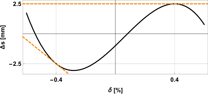
The idea of exploiting the different beam energies accelerating and decelerating within the same arc can be extended to independently control the path lengths and linear longitudinal dispersions of both accelerating and decelerating beams with the right choice of on-momentum first, second and third order longitudinal dispersions. This added flexibility to common transport arcs would however require sextupoles and octupoles to adequately set the higher order longitudinal dispersions while still keeping control over the transverse dispersions and chromatic amplitudes with a wide energy acceptance. Since this method does not provide control over the higher order dispersions as seen by the off-momentum beams, it is potentially useful to implement in arcs where the beam chirp is expected to be zero, and recuperate some path length control between accelerating and decelerating arcs. Figure 13 shows an example where the higher energy beam has a path length longer than the lower energy beam and their effective values are and respectively. The on-momentum longitudinal dispersions , and are , and respectively.
We also consider a configuration where the top energy arc can only be used to compress the bunch, but not to decompress it, as shown in Fig. 14. In this case, we can set an intermediate arc to have the opposite sign. With this scheme, the bunch decompression (black and orange dashed lines) is larger during deceleration (green dashed line) thanks to the combination of the energy spread growth in the interaction region and the adiabatic growth of the relative energy spread in the decelerating RF phases between the top and the decompressing arc (red and blue dashed lines).
X Parasitic crossings
Parasitic crossings, also know as overcompressions, where the bunch head and tail exchange places, provide an additional tool to find longitudinal matches in ERLs as, in effect, they allow the sign of the beam chirp during transport to change between linac passes. Within our model, this corresponds to a negative inverse global compression function . One could expect significant degradation to occur at a parasitic compression, and this would be of particular concern during acceleration. However if the minimum bunch length during this compression is relatively large due to the presence of uncompensated RF curvature at that location, such degradation would be not significant. One can picture this as the bunch “rolling” through a “banana” shape in the phase space, as opposed to standing totally upright.
Bunch decompression immediately after the IP in a compressive match can be such that the bunch chirp is of the opposite sign before and after. The bunch undergoes a parasitic crossing and the bunch energy spread can still be compressed during deceleration by changing the side of trough it is decelerated on with the effect of an imaginary resultant beam load. The collective effects during this process will degrade the beam’s emittance, however this happens after the interaction region and control of higher order longitudinal dispersion can be used to ensure energy recovery remains satisfied. This sequence of longitudinal manipulations is shown in Fig. 15.
First-order transformations like these, via control of , can be used to control second-order parameters of our beam and completely or partially cancel the effects of the rf curvature, as shown in Fig. 16, such that it is then compensated by the remaining RF passes. In order to continue the chirp compensation, the subsequent passes must be on the opposite side of the waveform.
This mechanism, if implemented in a common transport configuration with shared longitudinal dispersions and arc path-lengths requires parasitic crossings during acceleration, deceleration and at top energy, as shown in Fig. 17. The parasitic crossing during acceleration would have the same linearizing effect as during deceleration, but it would also increase the beam emittance before the interaction point. This alternative method of linearization is also applicable in energy spread minimizing matches with the exception of crossings happening at the top energy since the beam would have zero chirp at that point.
The separate transport configurations’ independent control over each arc’s longitudinal dispersions enables the use of this transformations during deceleration without compromising the beam quality before it reaches the interaction region. As the beam quality constraints during deceleration are relaxed, a separate transport can also compress the bunch during deceleration to cope with the energy spread increases expected from an FEL interaction. This is showcased in Fig. 18, showing the beam during acceleration without compressions or parasitic crossings and during deceleration after doubling its energy spread.

XI Conclusions
In this paper we have shown possible longitudinal matches for a wide range of multi-pass ERL configurations comprising compressive matches and energy spread minimising matches for common transport and separate transport topologies and with and without synchrotron radiation compensation as summarized by Fig.2. We conclude that for systems with negligible energy losses, arc path length and longitudinal dispersion configurations exist for both compressive matches and energy spread minimising matches for both common transport and separate transport topologies, although common transport matches will require a more intricate linearizaiton scheme to obtain linearized bunches at both the interaction point and dump.
If synchrotron radiation energy losses must be compensated, we show solutions for compressive matches and energy spread minimising matches for separate transport configurations. Synchrotron radiation compensating compressive matches are also available in common transport configurations. However, synchrotron radiation compensating energy spread minimising matches in a common transport configuration require transport between rf passes with energy acceptances of a few % as shown in Fig. 9 or require strong bunch length modulations including parasitic crossings throughout all of the transport, especially if peak energies are in the range of as proposed for LHeC.
Throughout this analysis, no collective effects have been taken into account. The two collective effects that will have the highest impact on the longitudinal phase space will be coherent synchrotron radiation (CSR) and longitudinal space charge (LSC). CSR will lower the energy at the center of the bunch with respect to the tails. This is opposite to the curvature imprinted by the rf on an accelerating beam and thus will reduce our linearization requirements. However, during deceleration, the changes in the longitudinal phase space from CSR will add to the decelerating RF curvature which together with the adiabatic growth of the energy spread during deceleration will result in a significant energy spread at the dump if not accounted for. LSC can be introduced in our considerations by tracking the bunch through the low energy sections Khan et al. 2019 and taking the pre-accelerated bunch as the start of our analysis and tracking the last decelerating pass towards the dump.
With these caveats, we have demonstrated a methodology for designing multi-pass ERLs for a wide range of applications.
XII Acknowledgments
This work was partially funded by STFC grant ST/P002056/1 “The Cockcroft Institute of Accelerator Science and Technology”.
References
- Tigner (1965) M. Tigner, Il Nuovo Cimento Series 10 37, 1228 (1965), ISSN 00296341.
- Burnett et al. (2020) A. Burnett, M. Borghesi, A. Comley, M. Dean, S. Diaz-moreno, D. Dye, A. Higginbotham, A. Kirrander, J. Marangos, M. Mcmahon, et al., UK-XFEL Science Case (2020).
- Benson et al. (1999) S. Benson, G. Biallas, C. Bohn, D. Douglas, H. F. Dylla, R. Evans, J. Fugitt, R. Hill, K. Jordan, G. Krafft, et al., Nuclear Instruments and Methods in Physics Research, Section A: Accelerators, Spectrometers, Detectors and Associated Equipment 429, 27 (1999), ISSN 01689002, URL https://www.osti.gov/biblio/791572.
- Sands (1970) M. Sands, Conf.Proc. C6906161, 257 (1970).
- Setiniyaz et al. (2020) S. Setiniyaz, R. Apsimon, and P. H. Williams, Implications of beam filling patterns on the design of recirculating energy recovery linacs (2020), URL https://link.aps.org/doi/10.1103/PhysRevAccelBeams.23.072002.
- Setiniyaz et al. (2021) S. Setiniyaz, R. Apsimon, and P. H. Williams, Physical Review Accelerators and Beams 24, 61003 (2021), ISSN 24699888, URL https://doi.org/10.1103/PhysRevAccelBeams.24.061003.
- Ainsworth et al. (2016) R. Ainsworth, G. Burt, I. V. Konoplev, and A. Seryi, Physical Review Accelerators and Beams 083502, 1 (2016).
- Konoplev et al. (2020) I. V. Konoplev, Y. Shashkov, A. Bulygin, M. A. Gusarova, and F. Marhauser, Physical Review Accelerators and Beams 23, 71601 (2020), ISSN 24699888, URL https://doi.org/10.1103/PhysRevAccelBeams.23.071601.
- Bogacz et al. (2016) S. A. Bogacz, D. Douglas, C. Dubbe, A. Hutton, T. Michalski, F. Pilat, Y. Roblin, T. Satogata, M. Spata, C. Tennant, et al., ER @ CEBAF : A test of 5-pass energy recovery at CEBAF (2016).
- Méot et al. (2016) F. Méot, I. Ben-Zvi, Y. Hao, P. Korysko, C. Liu, M. Minty, V. Ptitsyn, G. Robert-Demolaize, T. Roser, P. Thieberger, et al., IPAC 2016 - Proceedings of the 7th International Particle Accelerator Conference pp. 1022–1024 (2016).
- Angal-Kalinin et al. (2018) D. Angal-Kalinin, G. Arduini, B. Auchmann, J. Bernauer, A. Bogacz, F. Bordry, S. Bousson, C. Bracco, O. Brüning, R. Calaga, et al., Journal of Physics G: Nuclear and Particle Physics 45, 065003 (2018), ISSN 0954-3899, URL http://dx.doi.org/10.1088/1361-6471/aaa171.
- Arnold et al. (2019) M. Arnold, T. Bahlo, M. Dutine, R. Grewe, J. Hanten, L. Jürgensen, J. Pforr, N. Pietralla, F. Schließmann, M. Steinhorst, et al., pp. 1–4 (2019).
- Tsai et al. (2017) C.-Y. Tsai, S. Di Mitri, D. Douglas, R. Li, and C. Tennant, Physical Review Accelerators and Beams 20, 024401 (2017), ISSN 2469-9888, URL http://link.aps.org/doi/10.1103/PhysRevAccelBeams.20.024401.
- Zagorodnov and Dohlus (2011) I. Zagorodnov and M. Dohlus, Physical Review Special Topics - Accelerators and Beams 14, 1 (2011), ISSN 10984402.
- Bane and Emma (2005) K. L. Bane and P. Emma, Proceedings of the IEEE Particle Accelerator Conference 2005, 4266 (2005).
- Williams et al. (2020) P. H. Williams, G. Pérez-Segurana, I. R. Bailey, S. Thorin, B. Kyle, and J. B. Svensson, Physical Review Accelerators and Beams 23, 1 (2020), ISSN 24699888.
- Douglas (2001) D. Douglas, Beam Dynamics Newsletter ICFA-BD-NL, 40 (2001), URL https://icfa-usa.jlab.org/archive/newsletter/icfa_bd_nl_26.pdf.
- Piot et al. (2003) P. Piot, D. R. Douglas, and G. A. Krafft, Physical Review Special Topics - Accelerators and Beams 6, 25 (2003), ISSN 10984402.
- Nergiz et al. (2021) Z. Nergiz, N. S. Mirian, A. Aksoy, D. Zhou, F. Zimmermann, and H. Aksakal, Physical Review Accelerators and Beams 24, 100701 (2021), ISSN 24699888, URL https://doi.org/10.1103/PhysRevAccelBeams.24.100701.
- Konoplev et al. (2021) I. V. Konoplev, S. A. Bogacz, Y. Shashkov, and M. A. Gusarova (2021).
- LHeC and FCC-he Study Group (2020) LHeC and FCC-he Study Group, Tech. Rep. (2020).
- Koscica et al. (2019) R. Koscica, N. Banerjee, G. H. Hoffstaetter, W. Lou, and G. Premawardhana, Physical Review Accelerators and Beams 22 (2019), ISSN 24699888.
- Lindstrøm and Adli (2016) C. A. Lindstrøm and E. Adli, Physical Review Accelerators and Beams 19, 071002 (2016), ISSN 2469-9888, URL https://link.aps.org/doi/10.1103/PhysRevAccelBeams.19.071002.
- Khan et al. (2019) A. Khan, O. Boine-Frankenheim, F. Hug, and C. Stoll, Nuclear Instruments and Methods in Physics Research, Section A: Accelerators, Spectrometers, Detectors and Associated Equipment 948, 162822 (2019), ISSN 01689002, URL https://doi.org/10.1016/j.nima.2019.162822.