Fluxons in high-impedance long Josephson junctions
Abstract
The dynamics of fluxons in long Josephson junctions is a well-known example of soliton physics and allows for studying highly nonlinear relativistic electrodynamics on a microscopic scale. Such fluxons are supercurrent vortices that can be accelerated by a bias current up to the Swihart velocity, which is the characteristic velocity of electromagnetic waves in the junction. We experimentally demonstrate slowing down relativistic fluxons in Josephson junctions whose bulk superconducting electrodes are replaced by thin films of a high kinetic inductance superconductor. Here, the amount of magnetic flux carried by each supercurrent vortex is significantly smaller than the magnetic flux quantum . Our data show that the Swihart velocity is reduced by about one order of magnitude compared to conventional long Josephson junctions. At the same time, the characteristic impedance is increased by an order of magnitude, which makes these junctions suitable for a variety of applications in superconducting electronics.
The Josephson effect and weak links in superconductors Josephson 1964; Josephson 1965 are at the basis of a wide range of applications within superconducting electronics and many related fields. The well-known examples are superconducting quantum interference devices Jaklevic et al. 1964; Zimmerman et al. 1970; Mercereau 1970; Clarke 1966, voltage standard circuits Taylor et al. 1967; Field et al. 1973; Hamilton 2000, and superconducting qubits Makhlin et al. 1999; Clarke and Wilhelm 2008. The dynamics of charges and electromagnetic fields in Josephson junctions (JJs) is governed by the phase difference between the overlapping wave functions of superconducting electrodes Josephson 1964; Josephson 1965. In spatially extended JJs, the phase difference can vary in both time and space, which gives rise to a variety of propagating electromagnetic excitations. Common examples are linear waves formed by plasma oscillations of the Cooper pair density (Josephson plasmons), particle-like nonlinear wave packets with conserved amplitude, shape, and velocity (solitons) Barone et al. 1971; Scott et al. 1973; Scott et al. 1976; McLaughlin and Scott 1978; Lomdahl 1985, as well as their bound states formed by soliton-antisoliton pairs oscillating around their common center of mass (breathers) Kaup and Newell 1978; Kivshar and Malomed 1989.
In Josephson junctions, solitons occur in the form of Josephson vortices, often called fluxons Scott et al. 1973; Scott et al. 1976; McLaughlin and Scott 1978; Ustinov 1998, which are pinned at the tunnel barrier plane and may propagate along this plane Kulik 1967a; Scott et al. 1976; Matsuda and Kawakami 1983. By applying a bias current across the junction, these vortices can be accelerated up to the speed of light inside the Josephson transmission line, which is noted as Swihart velocity Swihart 1961. The vortex’s supercurrent is associated with a spatially localized -kink in the superconducting phase difference across the junction. In “conventional” JJs, bulk electrodes provide complete magnetic screening, so that the fluxoid quantization of the phase in units is linked to the magnetic flux carried by the vortex, which in turn is quantized in units of the magnetic flux quantum Josephson 1964; Josephson 1965.
The system’s properties such as velocity and spatial extension of a fluxon are governed by the tunnel barrier’s capacitance and critical current density as well as the lead inductance along the propagation direction. The precise controllability of these parameters qualifies Josephson vortices as excellent candidates for quantitative exploration of soliton physics. A preferred toy model is a quasi one-dimensional long Josephson junction (LJJ), whose length exceeds the characteristic spatial scale of the vortex , whereas the width is much smaller than . Extensive experiments in the past demonstrated, for instance, soliton-(anti)soliton interactions Ustinov 1998; Fujimaki et al. 1987, interplay with cavity resonances Chen et al. 1971; Fulton and Dynes 1973; Fiske 1964; Kulik 1965; Kulik 1967b, Lorentz contraction of relativistic solitons Matsuda and Kawakami 1983; Laub et al. 1995, and flux-flow dynamics of dense chains of solitons Yoshida et al. 1978; Nakajima et al. 1978. The latter regime finds its applications in microwave and millimeter-wave generation Nagatsuma et al. 1983; Koshelets et al. 2001 and amplification of microwave signals Nagatsuma et al. 1985; Nordman 1995.
In all previous experiments with conventional JJs, the typical Swihart velocity was about a few percent of the light velocity in vacuum, while the junction’s characteristic impedance was typically less than a few Ohms Barone and Paterno 1982; Likharev 1986; Holdengreber et al. 2019. These parameters are limited by the electrode’s geometric inductance, which is given by the magnetic field penetration depth in the bulk superconducting electrodes and confined by the feasible structure size. In particular, the very low characteristic impedance of LJJs remained the major obstacle limiting their applications in superconducting electronics.
In this work, we overcome the above constraints by at least one order of magnitude via replacing the bulk electrodes of LJJ with a high kinetic inductance superconductor (HKIS), which increases the total inductance of the Josephson transmission line beyond the purely geometrical limit. Using the sine-Gordon model, we evaluate the impact of kinetic inductance on the Swihart velocity, Josephson length, and junction impedance. We verify these predictions by transport measurements at different magnetic fields, temperatures, and under microwave irradiation. We demonstrate a reduction of the Swihart velocity by one order of magnitude compared to the conventional junctions. Correspondingly, we estimate the characteristic impedance of our junctions to be a few tens of Ohms, opening the way towards matching them to standard 50-Ohm microwave cables and circuits.

Conventional LJJs can theoretically be modeled by lumped elements of resistively and capacitively shunted junctions Josephson 1964; Stewart 1968; McCumber 1968 in -direction, which are extended along the -axis and thus connected via inductive leads. A finite resistance in parallel to an inductor in the equivalent scheme is due to surface losses Scott 1964, see Fig. 1 (b). The resulting perturbed sine-Gordon equation Barone et al. 1971; Ustinov 1998
| (1) |
describes the junction’s phase dynamics . The time and the spatial coordinate are normalized to and , respectively, with the Josephson plasma frequency as inverse time scale and the Josephson penetration length as the characteristic length. Here denotes the critical current density of the tunnel barrier, its specific capacitance, and the lead inductance per square. The left side of the perturbed sine-Gordon equation (1) is a wave equation, which describes the Josephson transmission line with the characteristic (Swihart) velocity Swihart 1961. The terms on the right side of Eq. (1) denote perturbations, namely a normalized bias current density , ohmic dissipation due to quasiparticle tunneling , and the surface resistance losses in the superconducting leads .
The sine-Gordon model remains valid Alfimov and Popkov 1995 even with additional lumped elements of kinetic inductance in the electrodes. Here we compliment with a kinetic part. This additional kinetic inductance of the electrode material comes along with a larger magnetic field penetration depth , which significantly modifies the vortex shape in such LJJs (see Fig. 1 (c) vs. Fig. 1 (d)). The vortex current distributes inhomogeneously over the whole film thicknesses of the HKIS electrodes , . This yields reduced effective participation of the bulk kinetic inductance to the Josephson length . We take this effect into account by introducing a geometrical factor , such that for the junction’s total lead inductance holds .
Compared to conventional long Josephson junctions, here the enlarged results in slower Swihart velocity and smaller vortex size Alfimov and Popkov 1995 while the junction impedance Langenberg et al. 1966, correspondingly, increases. The lead inductance along (see Fig. 1 (b)) plays a minor role for supercurrent oscillations across the barrier, that is why the change in does not affect the Josephson plasma frequency, to the first order. Furthermore, a substantial fraction of the vortex’s total phase winding drops at the dominating kinetic inductance, which generates no magnetic field and results in incomplete magnetic screening. The phase winding (fluxoid) quantization remains valid, but it does no longer necessitate quantized magnetic flux. The magnetic flux transported by a Josephson vortex is thus significantly smaller than , so that this kind of vortex can be more correctly noted as “fluxoid” instead of “fluxon”. Similar fluxoids were previously observed in arrays of JJs van der Zant et al. 1991, where the current distribution is predefined by the array geometry. Our approach to impedance-tailored LJJs provides fluxoids in a continuous Josephson medium where the current distribution evolves with no spatial constraints.

The high kinetic inductance superconductor of our choice is a thin film of granular aluminum oxide (). Thin superconducting films of granular aluminum oxide have been used to establish macroscopic circuit quantum electrodynamics. This material consists of pure aluminum grains separated by intrinsic nanoscale tunnel barriers (TB) Deutscher et al. 1973a, which strongly influence both the normal and the superconducting transport properties. In the superconducting state, this granular material can be considered as a disordered network of Josephson junctions Deutscher et al. 1973a, each of them providing a kinetic-type Josephson inductance Josephson 1964 related to the junction normal state tunnel resistance and the superconducting gap by Mattis and Bardeen 1958; Glover and Tinkham 1957; Annunziata et al. 2010; Rotzinger et al. 2016; Maleeva et al. 2018. The conductivity and inductance of HKIS formed by can vary over five orders of magnitude Deutscher et al. 1973b; Chui et al. 1981, depending on the oxygen concentration in the nanoscale TBs Ziemann et al. 1978, which is controlled by the oxygen partial pressure during the reactive sputtering process Rotzinger et al. 2016. This enormous versatility enables us using for different purposes, e.g., for depositing junctions with an HKIS in the bottom electrode, for depositing an insulating TB, and for forming a top electrode as a combination of HKIS and pure aluminum, as illustrated in Fig. 1 (b). As summarized in Tab. 1, we have fabricated three different junction stacks (A, B, and C) with varied values of and .
Since the normal sheet resistance is the crucial parameter to obtain the desired kinetic inductance per unit square , we monitor both the film thickness and sheet resistance during the film deposition. This in-situ measurement allows us to fit the theoretical model for fine-grained polycrystalline thin films Mayadas et al. Mayadas et al. 1969 and to determine the specific resistance . For sample A, its value is yielding for a thick film (for details see Supplementary Material S1).
As the oxygen partial pressure can be adjusted during sputtering process, this kind of measurement is a powerful tool to achieve the aimed kinetic inductance value, with an accuracy of about , at a fixed film thickness. Figure 2 depicts such adjustments as knees and the creation of a tunnel barrier (emphasized in the inset). By reaching the targeted resistance at the end of the static oxidation process, we can assume the complete oxidation of the aluminum layer and also estimate the barrier thickness.
The junctions were patterned from trilayers by using etching and anodic oxidization processes Gurvitch et al. 1983; Murduck et al. 1989. The fabricated JJs were intentionally varied in length, width, and geometry. The latter defines the distribution of the bias current over the junction Owen and Scalapino 1967; Schwidtal 1970 and therefore affects the vortex dynamics. As discussed in detail in the Supplementary Material S1, we fabricated junctions of square, inline and (quasi-)overlap geometries Sarnelli et al. 1991. We characterized the fabricated JJs (see Fig. 1(a)) by transport measurements at millikelvin temperatures and determined their characteristic parameters , and independently.
|
|
|
|
|
|
|
|
| ||||||||||||||||||||||||||
|---|---|---|---|---|---|---|---|---|---|---|---|---|---|---|---|---|---|---|---|---|---|---|---|---|---|---|---|---|---|---|---|---|---|---|
| A | 0.03 | 2 | LJJ limit not reached for | 0.03 | 0.04 | |||||||||||||||||||||||||||||
| B | 0.3 | 9 | 2.2 | 4 | 0.06 | 0.02 | 0.06 | |||||||||||||||||||||||||||
| C | 0.01 | 9 | 1.8 | 3 | 0.08 | 0.03 | 0.4 | |||||||||||||||||||||||||||
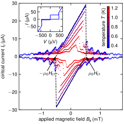
In the first experiment, we determine the fluxoid’s spatial extensions in both and direction, the Josephson length and the magnetic thickness of the tunnel barrier from measurements of the dependence of the critical current on magnetic field applied in the plane of the tunnel barrier. Examples of such critical current versus field patterns are depicted in Fig. 3. In high in-plane magnetic fields, where the junction is considered to be completely penetrated by magnetic flux along the axis, is determined from the critical current’s periodicity by . As can be seen in Tab. 1, affects , since the proximitized top electrode’s London penetration depth enlarges with increasing , whereas the bottom electrode of each stack is in the thin film limit and thus contributes to with Weihnacht 1969. Together with the first critical field , above which vortices can enter the junction, we calculate the vortex size Ferrell and Prange 1963 and the kinetic inductance contributing locally to . The comparison of this value with the kinetic inductance of the bottom layer , estimated from the resistance measured in situ as during the sample deposition, yields the geometry factor on the order of , as given in Tab. 1.
In a second experiment, we determine the Swihart velocity from equidistant subgap current singularities originating in junction cavity mode excitations. In zero magnetic fields, these excitations are Josephson vortices, which are accelerated by the bias current, causing a Lorentz force, and reflected at the edges while reversing their polarity. Such resonant vortex oscillations manifest as current steps at integer multiples of the first zero-field step (ZFS) Fulton and Dynes 1973. Another kind of current singularities arises above the critical magnetic field where the Josephson frequency of a biased junction excites electromagnetic standing waves in the junction cavity. Such singularities are known as Fiske steps (FS) and occur at voltages with half the periodicity of ZFS Fiske 1964; Kulik 1965; Kulik 1967b. As the vortex propagation velocity depends on the bias current and the damping parameter , the characteristic shape of the th ZFS step is given by McLaughlin and Scott 1978
| (2) |
The Swihart velocity is determined by the periodicity of the current singularities and the known junction length (see Tab. 1). As the junctions are underdamped (note the large hysteresis between critical and retrapping currents in the IV characteristics in the inset of Fig. 3), for reliably observing these current singularities arising from the subgap resistance branch it helps to increase the damping by increasing temperature of the sample. Then, however, the Stewart-McCumber branch cuts the lower part of the higher-order steps, as shown in Fig. 4. For underdamped junctions, cavity oscillations are unstable for Cirillo et al. 1997; Cirillo et al. 1998, which explains missing the first FS in Fig. 4.


In the third experiment, we determine the Josephson plasma frequency by measuring the plasma resonance of a square-shaped junction made of the trilayer with the tunnel barrier TB. The Josephson plasma oscillations are excited by applying external microwave irradiation. Resonant, subharmonic, or superharmonic driving Grønbech-Jensen et al. 2004 causes a multi-valued switching current from the zero to the nonzero voltage state. The secondary peaks in the switching current distribution Wallraff et al. 2003a; Grønbech-Jensen et al. 2004; Blackburn et al. 2010 (see inset of Fig. S3 in S2.2) are identified as resonant currents, for which the fixed external drive frequency equals the Josephson plasma resonance frequency , its integer multiples, or its fractions of . Since the bias current tilts the washboard potential of a JJ Martinis et al. 1985 and thus affects its shape, the associated internal oscillation frequency holds Dahm et al. 1968. Orthogonal distance regression, as shown in Fig. S3, yields the plasma frequency , the critical current , and hence the specific tunnel barrier capacitance .
To analyze the impact of the electrode’s kinetic inductance on LJJs, their characteristic parameters, listed in Tab. 1, are compared with estimations for conventional LJJs with equal tunnel barrier properties and , but made from pure aluminum. Here we assume that pure aluminum electrodes have negligible kinetic inductance. The result of this comparison is that the electrode’s kinetic inductance reduces both the Josephson length and the Swihart velocity by a factor of up to , while the Josephson plasma frequency remains nearly unchanged. Accordingly, the wave impedance of LJJs is increased by the same factor. The inductance contributing to Josephson plasma oscillations is dominated by the macroscopic stack TB rather than the nanoscopic TBs in due to the much stronger intergrain coupling, so that the increase of can be neglected to the first order. The combination of the independently measured parameters corresponds to the conventional sine-Gordon model with modified .
In conclusion, our results demonstrate a significantly reduced Swihart velocity in long Josephson junctions fabricated with high kinetic inductance electrodes. In our work, we used disordered oxidized aluminum as a high kinetic inductance superconductor. Our experiments demonstrate a decrease in the vortex’s size and a reduction of its limiting (Swihart) velocity by about one order of magnitude in comparison with conventional LJJs. The measured Swihart velocities down to a small fraction of of the light velocity in vacuum, in turn, correspond to an increase junction’s wave impedance up to compared to of conventional, similarly made LJJs. The high-kinetic inductance electrodes thus enable tailoring the junction impedance and facilitate solving the long-standing problem of impedance matching LJJs to external circuits and cables. Matching the impedance to external loads is crucial for increasing the efficiency of Josephson flux-flow oscillators used for microwave generation and amplification. Furthermore, the reduction of vortex size results in fewer charges participating in internal junction dynamics, a smaller effective capacitance over the vortex area and thus increases the effective charging energy . As plays the key role in experimentally reaching the quantum regime of Josephson vortex dynamics Wallraff et al. 2003b, high kinetic inductance electrodes also facilitate observing the quantum electrodynamics phenomena in long Josephson junctions.
The authors are grateful for fruitful discussions with A. Shnirman, J. Lisenfeld, T. Wolz, and M. Spiecker. We also thank L. Radtke for his assistance during the sample fabrication. The work was supported bilaterally by the German Science Foundation (DFG) through grant No. US 18/18-1 and the Russian Science Foundation through grant No. 19-42-04137. We also acknowledge support from the Landesgraduiertenförderung of the state Baden-Württemberg (M.W.), the Helmholtz International Research School for Teratronics (J.N.V. and Y.S.), and the Carl Zeiss Foundation (A.S.), as well as partial support by the Ministry of Education and Science of the Russian Federation in the framework in the framework of the Program of Strategic Academic Leadership ”Priority 2030” (M.V.F. and A.V.U.).
References
- Josephson (1964) B. D. Josephson, Reviews of Modern Physics 36, 216 (1964).
- Josephson (1965) B. D. Josephson, Advances in Physics 14, 419 (1965).
- Jaklevic et al. (1964) R. C. Jaklevic, J. Lambe, A. H. Silver, and J. E. Mercereau, Physical Review Letters 12, 159 (1964).
- Zimmerman et al. (1970) J. E. Zimmerman, P. Thiene, and J. T. Harding, Journal of Applied Physics 41, 1572 (1970).
- Mercereau (1970) J. Mercereau, Revue de physique appliquée 5, 13 (1970).
- Clarke (1966) J. Clarke, Philosophical Magazine 13, 115 (1966).
- Taylor et al. (1967) B. N. Taylor, W. H. Parker, D. N. Langenberg, and A. Denenstein, Metrologia 3, 89 (1967).
- Field et al. (1973) B. F. Field, T. F. Finnegan, and J. Toots, Metrologia 9, 155 (1973).
- Hamilton (2000) C. A. Hamilton, Review of scientific instruments 71, 3611 (2000).
- Makhlin et al. (1999) Y. Makhlin, G. Schön, and A. Shnirman, Nature 398, 305 (1999).
- Clarke and Wilhelm (2008) J. Clarke and F. K. Wilhelm, Nature 453, 1031 (2008).
- Barone et al. (1971) A. Barone, F. Esposito, C. Magee, and A. Scott, La Rivista del Nuovo Cimento (1971-1977) 1, 227 (1971).
- Scott et al. (1973) A. C. Scott, F. Y. F. Chu, and D. W. McLaughlin, Proceedings of the IEEE 61, 1443 (1973).
- Scott et al. (1976) A. C. Scott, F. Y. Chu, and S. A. Reible, Journal of Applied Physics 47, 3272 (1976).
- McLaughlin and Scott (1978) D. W. McLaughlin and A. C. Scott, Physical Review A 18, 1652 (1978).
- Lomdahl (1985) P. Lomdahl, Journal of Statistical Physics 39, 551 (1985).
- Kaup and Newell (1978) D. J. Kaup and A. C. Newell, Proceedings of the Royal Society of London. A. Mathematical and Physical Sciences 361, 413 (1978).
- Kivshar and Malomed (1989) Y. S. Kivshar and B. A. Malomed, Reviews of Modern Physics 61, 763 (1989).
- Ustinov (1998) A. V. Ustinov, Physica D: Nonlinear Phenomena 123, 315 (1998).
- Kulik (1967a) I. Kulik, JETP 24, 1307 (1967a).
- Matsuda and Kawakami (1983) A. Matsuda and T. Kawakami, Physical Review Letters 51, 694 (1983).
- Swihart (1961) J. C. Swihart, Journal of Applied Physics 32, 461 (1961).
- Fujimaki et al. (1987) A. Fujimaki, K. Nakajima, and Y. Sawada, Physical Review Letters 59, 2895 (1987).
- Chen et al. (1971) J. T. Chen, T. F. Finnegan, and D. N. Langenberg, Physica 55, 413 (1971).
- Fulton and Dynes (1973) T. Fulton and R. Dynes, Solid State Communications 12, 57 (1973).
- Fiske (1964) M. D. Fiske, Reviews of Modern Physics 36, 221 (1964).
- Kulik (1965) I. O. Kulik, ZhPmR 2, 134 (1965).
- Kulik (1967b) I. O. Kulik, Soviet Physics-Technical Physics 12, 111 (1967b).
- Laub et al. (1995) A. Laub, T. Doderer, S. G. Lachenmann, R. P. Huebener, and V. A. Oboznov, Physical Review Letters 75, 1372 (1995).
- Yoshida et al. (1978) K. Yoshida, F. Irie, and K. Hamasaki, Journal of Applied Physics 49, 4468 (1978).
- Nakajima et al. (1978) K. Nakajima, H. Ichimura, and Y. Onodera, Journal of Applied Physics 49, 4881 (1978).
- Nagatsuma et al. (1983) T. Nagatsuma, K. Enpuku, F. Irie, and K. Yoshida, Journal of Applied Physics 54, 3302 (1983).
- Koshelets et al. (2001) V. P. Koshelets, P. N. Dmitriev, A. B. Ermakov, A. S. Sobolev, A. M. Baryshev, P. R. Wesselius, and J. Mygind, Superconductor Science and Technology 14, 1040 (2001).
- Nagatsuma et al. (1985) T. Nagatsuma, K. Enpuku, H. Iwakura, and K. Yoshida, Japanese journal of applied physics 24, L599 (1985).
- Nordman (1995) J. E. Nordman, Superconductor Science and Technology 8, 681 (1995).
- Barone and Paterno (1982) A. Barone and G. Paterno, Physics and applications of the Josephson effect, A Wiley-Interscience publication (Wiley, New York [u.a.], 1982).
- Likharev (1986) K. K. Likharev, Dynamics of Josephson Junctions and Circuits (Gordon and Breach Science Publishers, Philadelphia, Pa. [u.a.], 1986).
- Holdengreber et al. (2019) E. Holdengreber, E. Schacham, and E. Farber, (2019), 10.1049/cp.2019.0731.
- Stewart (1968) W. C. Stewart, Applied Physics Letters 12, 277 (1968).
- McCumber (1968) D. E. McCumber, Journal of Applied Physics 39, 3113 (1968).
- Scott (1964) A. C. Scott, Solid-State Electronics 7, 137 (1964).
- Alfimov and Popkov (1995) G. L. Alfimov and A. F. Popkov, Physical Review B 52, 4503 (1995).
- Langenberg et al. (1966) D. N. Langenberg, D. J. Scalapino, and B. N. Taylor, Proceedings of the IEEE 54, 560 (1966).
- van der Zant et al. (1991) H. S. J. van der Zant, F. C. Fritschy, T. P. Orlando, and J. E. Mooij, Physical Review Letters 66, 2531 (1991).
- Deutscher et al. (1973a) G. Deutscher, H. Fenichel, M. Gershenson, E. Grünbaum, and Z. Ovadyahu, Journal of Low Temperature Physics 10, 231 (1973a).
- Mattis and Bardeen (1958) D. C. Mattis and J. Bardeen, Physical Review 111, 412 (1958).
- Glover and Tinkham (1957) R. E. Glover and M. Tinkham, Physical Review 108, 243 (1957).
- Annunziata et al. (2010) A. J. Annunziata, D. F. Santavicca, L. Frunzio, G. Catelani, M. J. Rooks, A. Frydman, and D. E. Prober, Nanotechnology 21, 445202 (2010).
- Rotzinger et al. (2016) H. Rotzinger, S. T. Skacel, M. Pfirrmann, J. N. Voss, J. Münzberg, S. Probst, P. Bushev, M. P. Weides, A. V. Ustinov, and J. E. Mooij, Superconductor Science and Technology 30, 025002 (2016).
- Maleeva et al. (2018) N. Maleeva, L. Grünhaupt, T. Klein, F. Levy-Bertrand, O. Dupre, M. Calvo, F. Valenti, P. Winkel, F. Friedrich, W. Wernsdorfer, et al., Nature communications 9, 1 (2018).
- Deutscher et al. (1973b) G. Deutscher, M. Gershenson, E. Grünbaum, and Y. Imry, Journal of Vacuum Science and Technology 10, 697 (1973b).
- Chui et al. (1981) T. Chui, G. Deutscher, P. Lindenfeld, and W. L. McLean, Physical Review B 23, 6172 (1981).
- Ziemann et al. (1978) P. Ziemann, G. Heim, and W. Buckel, Solid State Communications 27, 1131 (1978).
- Mayadas et al. (1969) A. F. Mayadas, M. Shatzkes, and J. F. Janak, Applied Physics Letters 14, 345 (1969).
- Gurvitch et al. (1983) M. Gurvitch, M. Washington, and H. Huggins, Applied Physics Letters 42, 472 (1983).
- Murduck et al. (1989) J. M. Murduck, J. Porter, W. Dozier, R. Sandell, J. Burch, J. Bulman, C. Dang, L. Lee, H. Chan, R. Simon, et al., IEEE Transactions on Magnetics 25, 1139 (1989).
- Owen and Scalapino (1967) C. S. Owen and D. J. Scalapino, Physical Review 164, 538 (1967).
- Schwidtal (1970) K. Schwidtal, Physical Review B 2, 2526 (1970).
- Sarnelli et al. (1991) E. Sarnelli, S. Pagano, B. Ruggiero, and M. Russo, IEEE Transactions on Magnetics 27, 2716 (1991).
- Barone et al. (1975) A. Barone, W. J. Johnson, and R. Vaglio, Journal of Applied Physics 46, 3628 (1975).
- Monaco et al. (2013) R. Monaco, V. P. Koshelets, A. Mukhortova, and J. Mygind, Superconductor Science and Technology 26, 055021 (2013).
- Weihnacht (1969) M. Weihnacht, physica status solidi (b) 32, K169 (1969).
- Ferrell and Prange (1963) R. A. Ferrell and R. E. Prange, Physical Review Letters 10, 479 (1963).
- Cirillo et al. (1997) M. Cirillo, T. Doderer, S. G. Lachenmann, F. Santucci, and N. Grønbech-Jensen, Physical Review B 56, 11889 (1997).
- Cirillo et al. (1998) M. Cirillo, N. Grønbech-Jensen, M. R. Samuelsen, M. Salerno, and G. V. Rinati, Physical Review B 58, 12377 (1998).
- Grønbech-Jensen et al. (2004) N. Grønbech-Jensen, M. G. Castellano, F. Chiarello, M. Cirillo, C. Cosmelli, L. V. Filippenko, R. Russo, and G. Torrioli, Physical Review Letters 93, 107002 (2004).
- Wallraff et al. (2003a) A. Wallraff, T. Duty, O. Lukashenko, and A. V. Ustinov, Physical Review Letters 90, 037003 (2003a).
- Blackburn et al. (2010) J. A. Blackburn, M. Cirillo, and N. Grønbech-Jensen, Physics Letters A 374, 2827 (2010).
- Martinis et al. (1985) J. M. Martinis, M. H. Devoret, and J. Clarke, Physical Review Letters 55, 1543 (1985).
- Dahm et al. (1968) A. J. Dahm, A. Denenstein, T. F. Finnegan, D. N. Langenberg, and D. J. Scalapino, Physical Review Letters 20, 859 (1968).
- Wallraff et al. (2003b) A. Wallraff, A. Lukashenko, J. Lisenfeld, A. Kemp, M. Fistul, Y. Koval, and A. Ustinov, Nature 425, 155 (2003b).
- Cohen and Abeles (1968) R. W. Cohen and B. Abeles, Physical Review 168, 444 (1968).
- Braumüller et al. (2015) J. Braumüller, J. Cramer, S. Schlör, H. Rotzinger, L. Radtke, A. Lukashenko, P. Yang, S. T. Skacel, S. Probst, M. Marthaler, L. Guo, A. V. Ustinov, and M. Weides, Physical Review B 91, 054523 (2015).
- Lukashenko and Ustinov (2008) A. Lukashenko and A. V. Ustinov, Review of Scientific Instruments 79, 014701 (2008).
- Fulton and Dunkleberger (1974) T. A. Fulton and L. N. Dunkleberger, Physical Review B 9, 4760 (1974).
- Devoret et al. (1985) M. H. Devoret, J. M. Martinis, and J. Clarke, Physical Review Letters 55, 1908 (1985).
- Ambegaokar and Baratoff (1963) V. Ambegaokar and A. Baratoff, Physical Review Letters 10, 486 (1963).
- Nicol et al. (1960) J. Nicol, S. Shapiro, and P. H. Smith, Physical Review Letters 5, 461 (1960).
- Maezawa et al. (1995) M. Maezawa, M. Aoyagi, H. Nakagawa, I. Kurosawa, and S. Takada, Applied Physics Letters 66, 2134 (1995).
Supplementary Material for “Fluxons in high-impedance long Josephson junctions”
S1 Experimental methods
The kinetic inductance of granular aluminum oxide () can be estimated by Rotzinger et al. 2016, where the superconducting gap is nearly constant for slightly different normal sheet resistances . The control of this is decisive to achieve the desired kinetic inductance Rotzinger et al. 2016. For this reason, we monitor both the film thickness and the normal resistance during the pulsed DC magnetron sputter deposition of . This measurement enables us to fit the specific conductance to estimate the final specific resistance in situ. To describe the thickness dependent specific conductance we use a model for fine-grained polycrystalline thin films by Mayadas et al. Mayadas et al. 1969
| (S1) |
that solves a linearized Boltzmann equation concerning ordinary scattering mechanisms as in bulk materials and superimposed scattering at grain boundaries. Here, denotes the intrinsic thickness independent conductivity from the film interior and is the ratio between the background mean free path and the film thickness , reduced by a scattering reflection coefficient . This estimation allows us to set the specific resistance accurately by readjusting the oxygen partial pressure if necessary and thus to achieve the desired sheet resistance at the fixed film thickness with a precision less than . The least-squares fit for trilayer A as shown in Fig. 2 allows an offset thickness, above which the model holds, and yields and . Assuming for Cohen and Abeles 1968, results in a and that confirms diffusive transport in the granular material. The discrepancy of the measurement and the theoretical model for small film thicknesses originated in a inhomogeneous film thickness and the conductivity of the argon plasma that contributes especially for small film thicknesses, where the film is not entirely connected.
The SIS tunnel junction stacks are grown on a c-plane sapphire substrate and patterned using photolithography and chlorine-based inductively coupled plasma etching. The junctions themselves are defined via anodic oxidation through a solvent of ammonium pentaborate in ethylene glycol and water, to isolate the top from the bottom electrodes. The leads to the upper aluminum electrodes are evaporated thermally, where the galvanic contact is ensured by previous argon milling Braumüller et al. 2015. The junction designs vary in length ( to ), width ( to ) and geometry.
The junction geometry governs the distribution of bias currents over the junction, which drives the vortex (see Fig. S1). Since short squared junctions provide the most homogeneous current distribution, they are used to determine stack characteristic quantities such as critical current density and plasma frequency. The inline geometry provides an inhomogeneous bias current distribution and is suitable for magnetic diffraction patterns. To improve the homogeneity of the bias current, as desired for the investigation of soliton dynamics, a quasi-overlap geometry Sarnelli et al. 1991 is used, where high kinetic inductance material is placed in the bias leads in junction vicinity.

The low-temperature measurements are performed either in a cryostat or in a dilution refrigerator, whereby the DC measurement lines are low-pass filtered using combinations of CLC, RCR and copper powder filters Lukashenko and Ustinov 2008 at different temperature stages. Magnetic fields are applied in-plane and external fields are suppressed by a surrounding Cryoperm® shield.
S2 Low temperature measurements
S2.1 Junction characterization
Transport measurements at low temperatures of about show IV-characteristics as in Fig. S2 (a). The large hysteresis between switching and retrapping current confirms a high quality factor and only little quasiparticle excitations. The critical currents and the ciritcal current densities are determined by switching current measurements and the Ambegaokar-Baratoff relation. In switching current measurements we detect the escape current from the zero-voltage to the nonzero-voltage state for events. The integral equation for the escape probability Fulton and Dunkleberger 1974
| (S2a) | |||
| can be solved for the escape probability density (epd), which reads | |||
| (S2b) | |||
| The epd depends on the current sweep rate and the thermal activation rate Devoret et al. 1985 | |||
| (S2c) | |||
Here, the junction’s potential is assumed as tilted washboard Stewart 1968; McCumber 1968 with the Josephson energy . From the fit of the epd of Eq. (S2b) with Eq. (S2c), shown in Fig. S2 (b), we can extract the critical current . For large squared junctions with areas of , this result coincides with the Ambegaokar-Baratoff model Ambegaokar and Baratoff 1963
| (S3) |
which estimates from the normal resistance and the two superconducting gaps . As typical for JJs with different superconductors the IV-characteristics show two effective gaps Nicol et al. 1960; Barone and Paterno 1982 at with the gap energies of proximitized aluminum and inversely proximitized disordered oxidized aluminum .
S2.2 Plasma frequency
In the washboard potential of a Josephson junction, thermally or microwave driven oscillations can excite the particle to the nonzero voltage state below the critical dc current Devoret et al. 1985. Off-resonant microwave irradiation superimposes a small AC contribution to the DC bias and thus lowers the switching current continuously with increasing amplitude. Resonant, sub- or superharmonic microwave irradiation, however, excites plasma oscillations that manifest as multi-valued switching current Wallraff et al. 2003a; Grønbech-Jensen et al. 2004; Blackburn et al. 2010. As the internal resonance frequency
| (S4) |
depends on DC bias current , such a secondary peak can be assigned as a resonance current to a fixed drive frequency, as shown in Fig. S3. To determine the plasma frequency , we take switching current distributions with events and irradiate various but fixed external drive frequencies with suitable drive power, so that two distinguishable peaks arise. Orthogonal distance regression yields a plasma frequency of , a critical current of and hence a specific capacitance of . This is a typical number for tunnel barriers made from thermally oxidized aluminum Maezawa et al. 1995 and indicates that the additional kinetic inductance does not affect the plasma frequency in the first order.