A Dynamic Codebook Design for Analog Beamforming in MIMO LEO Satellite Communications
Abstract
Beamforming gain is a key ingredient in the performance of LEO satellite communication systems to be integrated into cellular networks. However, beam codebooks previously designed in the context of MIMO communication for terrestrial networks, do not provide the appropriate performance in terms of inter-beam interference and gain stability as the satellite moves. In this paper, we propose a dynamic codebook that provides a stable gain during the period of time that the satellite covers a given cell, while avoiding link retraining and extra calculation as the satellite moves. In addition, the proposed codebook provides a higher signal-to-interference-plus-noise (SINR) ratio than those DFT codebooks commonly used in cellular systems.
I Introduction
New flexible payloads are becoming more common in emerging satellite services due to significant innovations in active antennas and modular processing blocks, among others [1], [2]. These new technologies pave the way for the integration of satellite communications in general, and LEO constellations in particular, into future cellular networks. However, many open challenges still need to be addressed at the physical layer, including the design of appropriate beamforming strategies, modulation and coding schemes or approaches for link adaption [3].
To provide the required beamforning gain, analog fully reconfigurable beamforming networks entail high mass and power dissipation, limiting the number of beams. In the particular case of LEO satellites, large efforts are underway to develop hybrid arrays combining analog beamforming at a subarray level with digital processing of subarrays. Despite the expected performance, especially for large arrays, the flexibility comes at a cost, in such a way that the most relevant massive LEO constellations [4, 5] which are either operational or near to be, still make use of fixed analog beams. However, and similarly to terrestrial cellular systems, some degree of beam steering is desirable to focus the resources at will, keeping in mind that the size of satellite beams is much larger than that for terrestrial beams, able to offer better spatial discrimination.
Beam codebooks for cellular networks being deployed are based on an oversampled 2-D Discrete Fourier Transform (DFT) type grid of beams [6, 7]. This design was adapted in [8] to LEO systems by using the interpolation factor to adjust the beamwidth to the size of the region of interest. However, as shown in [8], using this type of codebook results in a high signal-to-interference-plus-noise ratio (SINR) and a large variation in beamforming gain inside the beam switching time. In addition, the handovers between beams when using a static codebook are very frequent, degrading the user experience [9]. New designs that account for the mobility of the LEO satellite and the short amount of time that a given location is under the coverage of a LEO beam, need to be devised.
In this paper we address the problem of analog beamforming for LEO payloads with limited reconfigurability, by designing a family of codebooks that, together with the appropriate switching strategy, can steer the beams with limited resolution on the region to serve. The proposed design minimizes the number of handovers between beams for the ground terminal while keeping a stable beamforming gain during the period of time that the same LEO satellite is serving a given user.
II System model
We consider the link between a LEO satellite and a user terminal operating in the Ku band with a bandwidth and a full frequency reuse (FFR) scheme across beams. The user terminal is located in an elliptical region of interest (ROI) or coverage area with semi-radius and , designed following a given criteria, for example the one described in [8]. We denote with the axis in the direction of the satellite’s movement, while is the axis orthogonal to . The satellite is operating at a height with an associated angular speed of , where is the Earth’s radius and is the satellite linear speed. Note that the satellite linear speed also depends on the orbit height as
| (1) |
where is the Earth’s mass, and is the gravitational constant. We also define the region of proximity (ROP) as the elliptical region of the same size as the ROI located right under the satellite. Note that the ROI and ROP do not have to be exactly the same, since the exact location of the ROI depends on the main directions of the beampatterns generated at the satellite.
The satellite is equipped with uniform planar sub-arrays of size , for a total number of antenna elements . Note that while it is common to distribute the sub-arrays in a rectangular way, since each sub-array will be working independently of the others, their particular distribution will be irrelevant. By having the relative antenna elements positions defined by , with each of the radiating elements position at , and denoting as the unitary sphere, the steering vectors that describe the response of the satellite’s antenna in the direction are denoted as and defined as
| (2) |
The LEO satellite serves a number of mobile user terminals (UTs) on the ground by illuminating the ROI with analog beams that are chosen from a given codebook and move with the satellite. We denote the analog precoding matrix used by the satellite as . Given that the analog precoding stage will be implemented by means of a phase shifting network, we can write
| (3) |
where is the index of the RF-chain to which the -th antenna is connected. As in [10], we assume that the UTs exploit satellite’s position information for beam tracking. We are considering a uniform planar array (UPA) of size at the terminals. The UT steering vector is denoted as , and is defined as , where are the antenna elements relative positions. The UT combiner is denoted as , and is assumed to be analog-only.
We adopt a Rician geometric channel model with LoS complex gain and Rician factor as in [8]. Given the steering vectors for the satellite and the UT previously defined, and assuming perfect symbol and carrier synchronization, the equivalent channel matrix is
| (4) |
where is the satellite position, is the UT position, and is the Rician component satisfying . The term includes all path loss effects, dominated by the free space path loss and the atmospheric attenuation .

The signal-to-noise ratio (SNR) can be written in terms of the received signal strength (RSS) and the noise power as [11]
| (5) | |||
| (6) | |||
| (7) |
where is the transmit power, is the transmit antenna gain, is the cable loss between the antenna and the transmitter, and is the receiver antenna gain. Additionally, and denote the noise temperature and the Boltzmann constant, respectively. The receiver gain of this antenna when considering a Rician channel is extracted from [8] to be
| (8) |
Same as in [8], we include the gain due to capturing the Rician component of the channel in the receiver as a natural result to ease the formulation.
III Dynamic codebook design
Given a specific coverage area, our goal is to design a codebook of analog precoders that provides appropriate coverage, minimizing the SNR and SINR loss due to the satellite movement and the static beams. This loss has been described and numerically evaluated in [8] for a 2D DFT beam codebook as that used in 5G New Radio (NR). In this section, we design a set of feasible analog precoders that enable seamless communication without having to re-train the link every time a user is not covered anymore by a given beam due to the satellite’s movement.
There are three main ideas behind our design: 1) selection of a basic codebook that provides a better SINR than that associated to the DFT codebook; 2) introduction of a codebook adaptation mechanism so the SNR variation due to the satellite movement is compensated; and 3) definition of a beam ID permutation protocol over the codebook that minimizes handovers. In the next paragraphs we describe these different components of the final design.
III-A Initial codebook design
For the initial codebook design we choose to create beams whose maximum gains appear at the points of a given triangular (or hexagonal) lattice, as illustrated in Fig. 1. The points in the triangular lattice are scaled to be proportional to the diameter covered by a beam-width by a factor in the direction and by a factor in the direction, where is defined as the oversampling factor. The value of the oversampling factor is chosen to adjust the number of points of the triangular lattice that will fall inside the satellite’s shadow, i.e., the number of beams that will illuminate this region. The choice of a triangular lattice over a rectangular one (as that associated to a DFT codebook), gives rise to the common hexagonal tesselation in satellite footprints, and prevents the existence of locations with up to four beams with equal gain, highly detrimental for the signal-to-interference-plus-noise ratio (SINR). In addition, the alignment of the x-axis with the triangulation minimizes the periodicity interval of the lattice in that direction.

III-B Codebook adaptation
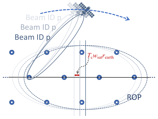
The main idea behind our design consists of automatically updating the analog precoder every time interval of length to compensate for the satellite’s movement without the explicit need of computing a new precoder, but simply playing it from a dynamic codebook in a predefined order. This is illustrated in Fig. 2 for one of the beams in the initial codebook. This way, the beam pattern that points to a specific point in the triangular lattice is updated in a temporal grid to keep a high gain while that point is within the reach of the satellite’s ROP. In an ideal system, the beampattern would be adapted instantaneously as the satellite moves, but in a practical system only a periodic adaptation is feasible.
To simplify the dynamic codebook design problem, we adopt the geometry of the stereographic projection (ignoring the Earth’s curvature and assuming the origin of coordinates is at the satellite’s location), and using the unitary direction of the satellite movement as x-axis and the perpendicular to the satellite movement and the orbital plan as the y-axis. The inaccuracies generated by this adoption can be neglected in the context of a LEO constellation, due to the high altitude of the satellites. Under this assumption, the condition of maximizing the stability of the directionality over the Earth’s surface is equivalent to correcting the relative movement of the UT with respect to the satellite due to the satellite movement, i.e. . Note that during the time interval the point of maximum directionality relative to the satellite moves a distance of in the opposite direction to the satellite’s movement. This tells us how to design the subsequent codebooks given an initial codebook.
Now we define the spatial shift in the axis of the satellite’s ROP over a period as for a given integer number . For an efficient implementation of the dynamic codebook, we realize that by setting such that the scaling factor satisfies , the lattice becomes invariant to the spatial shift . This means that by selecting an integer number , we can create a cyclic dynamic codebook where each iteration lasts , repeats every iterations (cycle), and, as we will explain in Section III-C, shuffles indices for coherence. Mathematically, the lattice points of the -th iteration can be expressed as
| (9) |
describes the lattice points assuming an infinite lattice, although for the definition of the final codebook we just need to keep those points that fall inside the coverage area. The condition for a point being inside the elliptical ROI is . Thus, we select the points in that fulfill this equation. We do this for each iteration , leading to a different number of points being inside the ellipse over time as changes, and in consequence having a slightly different number of RF-chains and active beams in use over time. This process is illustrated in Fig. 3 for , i.e., a dynamic codebook built from 4 static codebooks in 4 iterations. The duration if the cycle is in this case. Note that in each iteration, the number of active beams can decrease, increase, or keep unchanged, depending on the set of points of the triangular lattice that stay inside the corresponding ROP.
To compute the expression for the beamformers in the dynamic codebook as a function of the iteration , by considering a point at height with origin on the satellite?s shadow, the direction from the satellite to that point can be computed as . Constructive interference to create a narrow beam-pattern in that direction can be achieved by setting the satellite’s -th antenna’s phase-shift equal to the normalized satellite’s steering vector coefficient evaluated at that direction, i.e., . Note that the normalization factor depends on the size of the subarray connected to a specific RF chain. In consequence, for every iteration , with one RF-chain per beam pointing to , we can set the phase-shift coefficient of the -th antenna connected to that RF-chain to
| (10) |
for , and otherwise.
III-C Beam IDs permutations
Beam IDs are permuted at each iteration if the dynamic codebook to guarantee that the beam ID covering a given hexagonal area is static, as illustrated in Fig. 2. In terms of the directionality of the beam-pattern, this means that the point on the Earth’s surface such that a specific beam with ID at time has its maximum directionality, is also the maximum directionality point for the beam with ID at time .
 |
 |
 |
| (a) | (b) | (c) |
After completion of a cycle of the codebook, and due to the satellite movement, the Earth location initially illuminated by the beam pointing to the lattice point , becomes illuminated by the beam pointing to the lattice point , so that the beam index changes. To avoid the need of constant handover, a permutation of the beam indices can be applied under the constraint that if , then the index of the beam pointing to the lattice point gets updated to the index of the beam pointing to the lattice point . A proposal to address the index updating procedure starts by determining all the lattice points that will be eventually active: , then label them as for the th point, such that or if with respect to the coordinates of point if . With this, the updating procedure boils down to a cyclic increase of each beam index in one unit.
Note that when using this codebook, the cells on the Earth surface, considered as those locations receiving higher power from a given beam, will be nearly hexagonal, with sides at the equidistant lines to the six nearest lattice points as will be shown in the simulations.
| Parameter | Symbol | Value | Units |
| Constellation and ROI | |||
| Satellite height | km | ||
| Number of orbital planes | |||
| Number of satellites per orbital plane | |||
| Orbital plane inclination | degrees | ||
| Semiradius of the ROI in -dimension | 534.1 | km | |
| Semiradius of the ROI in -dimension | 170.5 | km | |
| Channel | |||
| Carrier frequency | GHz | ||
| Bandwidth | MHz | ||
| Atmospheric path loss | dB | ||
| Rician factor | |||
| Satellite | |||
| Sub-array elements in -dimension | |||
| Sub-array elements in -dimension | |||
| Number of RF chains | |||
| Transmit power | dBW | ||
| Oversampling factor | |||
| User terminal | |||
| User antenna gain | 27.6 | dB | |
| Receiver noise temperature | T | 24.1 | dB |
IV Simulation Results
We simulate the downlink of a LEO satellite communication system operating with the parameters described in Table I. The LEO constellation includes 53 satellites in each of its 83 orbits, with an orbital plane inclination of . Each satellite orbits at a km height, covering an ellipsoidal area with semi-radius km in the axis and km in the axis. The satellite large phased array consists of sub-arrays of antennas, which operate independently. The gain at the UT corresponds to that of a uniform rectangular array of elements, i.e., .
We start by analyzing the satellite’s coverage in the elliptical area when using a static initial codebook as described in Section III-A. To this end, since , and are user location dependent, we plot maps of the SNR and SINR in Fig. 4. The values of the SNR and SINR for each location have been computed using (15) and (19) in [8]. While the SNR values show relatively small variations all over the ellipse, the SINR map shows areas with relative high interference. This is a consequence of using the same codebook on a single satellite for all users over the whole bandwidth spectrum. A full frequency reuse leads to SINR values no larger than at those locations covered by three beams with the same gain. We compare now the performance provided by this initial codebook design with that of an oversampled 2D DFT codebook comprised of 15 beam-patterns, evaluated in [8] in the context of a LEO satellite communication system. To that aim, we evaluate the probability of the SINR being larger than a given threshold. Fig. 5 shows that our design significantly outperforms the 2D DFT codebook used in 5G NR even when using fewer beam-patterns to cover the same area, providing a higher probability of achieving a given SINR threshold. For example, the probability of having a SINR larger than 4 dB is 0.5 when using the proposed dynamic codebook, and only 0.25 when operating with a fixed 2D DFT codebook. These results show how the initial codebook design proposed in Section III-A outperforms the 2D DFT codebook.

Now we evaluate the performance of the dynamic codebook design based on the previous initial codebook. To this aim, we compute the SNR degradation over time due to the satellite’s movement. The UT is initially located at the center of the ROP, which is moving as the satellite travels. Fig. 6 shows the evolution of the SNR value when using the initial codebook without beam adaptation, and the proposed dynamic codebook. When using the initial codebook in a static way, we can see that the user is illuminated for around seconds by each beam-pattern, with an SNR variation of around 3dB inside the beam footprint. In addition, there is a progressive degradation of the peak gain that the best beam can provide. With the proposed dynamic codebook, the UT experiences an SNR with a variation of the order of only 0.5 dB over the same period of time.
 |
 |
| (a) | (b) |
We consider now the evolution of SNR over time for a user located 50 km away on the y-axis from the center of the ROP, using both the DFT codebook and the dynamic codebook. The results are shown in Fig. 7. In this case, the user experiences a variation of 1.5 dB with the static 2D DFT codebook, while the dynamic codebook provides approximately the same peak SNR over the analyzed cycles. These two examples show how the dynamic codebook clearly outperforms the static DFT codebook at different user locations.
 |
 |
| (a) | (b) |
Finally, we evaluate the ability of the beam ID permutation mechanism to reduce the number of handovers. Fig. 8 shows the number of handovers that a user located at a given point would experience when using the static and dynamic codebooks. It is easy to check that the number of handovers is kept to one for most of the locations in the ROI when using the dynamic codebook, while the static one requires at least three handovers for most of the locations.
 |
| (a) |
 |
| (b) |
V Conclusions
In this paper we have proposed a family of codebooks specifically designed for analog beamforming in LEO satellites, which affords some flexibility for beam steering without incurring in extra computational complexity at the payload. The selection of the appropriate codebook from a judiciously designed family allows to offer a smoother coverage to the ground terminals, minimizing handovers while keeping a stable beamforning gain.
References
- [1] R. De Gaudenzi, P. Angeletti, D. Petrolati, and E. Re, “Future technologies for very high throughput satellite systems,” Intl. Journal of Satellite Communications and Networking, vol. 38, no. 2, pp. 141–161, 2020.
- [2] P. Angeletti and R. De Gaudenzi, “A Pragmatic Approach to Massive MIMO for Broadband Communication Satellites,” IEEE Access, vol. 8, pp. 132 212–132 236, 2020.
- [3] O. Kodheli, A. Guidotti, and A. Vanelli-Coralli, “Integration of Satellites in 5G through LEO Constellations,” in GLOBECOM 2017 - 2017 IEEE Global Communications Conference, 2017, pp. 1–6.
- [4] I. del Portillo, B. G. Cameron, and E. F. Crawley, “A technical comparison of three low earth orbit satellite constellation systems to provide global broadband,” Acta Astronautica, vol. 159, pp. 123–135, 2019.
- [5] S. Xia, Q. Jiang, C. Zou, and G. Li, “Beam Coverage Comparison of LEO Satellite Systems Based on User Diversification,” IEEE Access, vol. 7, pp. 181 656–181 667, 2019.
- [6] H. Miao, M. D. Mueck, and M. Faerber, “Amplitude Quantization for Type-2 Codebook Based CSI Feedback in New Radio System,” in European Conf. on Networks and Communications (EuCNC), 2018, pp. 1–9.
- [7] Samsung, “WF on Type I and II CSI codebooks,” 3GPP, Hangzhou, China, Tech. Rep. Meeting RAN1#89, May 2017.
- [8] J. Palacios, N. Gonzalez-Prelcic, C. Mosquera, T. Shimizu, and C. H. Wang, “A hybrid beamforming design for massive MIMO LEO satellite communications,” Frontiers in Space Technologies, vol. 2, p. 4, 2021.
- [9] Y. Su, Y. Liu, Y. Zhou, J. Yuan, H. Cao, and J. Shi, “Broadband LEO Satellite Communications: Architectures and Key Technologies,” IEEE Wireless Communications, vol. 26, no. 2, pp. 55–61, 2019.
- [10] J. Kim, M. Y. Yun, D. You, and M. Lee, “Beam Management for 5G Satellite Systems Based on NR,” in International Conference on Information Networking (ICOIN), 2020, pp. 32–34.
- [11] Technical Specification Group Radio Access Network, “Solutions for NR to support non-terrestrial networks (NTN) (Release 16),” 3GPP, Tech. Rep. V16.0.0, dec 2019.