Science Case for the new High-Intensity Muon Beams HIMB at PSI
Abstract
In April 2021, scientists active in muon physics met to discuss and work out the physics case for the new High-Intensity Muon Beams (HIMB) project at PSI that could deliver of order s-1 surface muons to experiments. Ideas and concrete proposals were further substantiated over the following months and assembled in the present document. The high intensities will allow for completely new experiments with considerable discovery potential and unique sensitivities. The physics case is outstanding and extremely rich, ranging from fundamental particle physics via chemistry to condensed matter research and applications in energy research and elemental analysis. In all these fields, HIMB will ensure that the facilities SS and CHRISP on PSI’s High Intensity Proton Accelerator complex HIPA remain world-leading, despite the competition of muon facilities elsewhere.
1 Introduction
Muon physics covers research fields from fundamental particle physics to materials science. Muons are leptons with either negative or positive electric charge, such as electrons and positrons, but 207 times more massive and unstable. Muons are efficiently produced in weak decays of pions which are usually produced by proton beams hitting nuclei in some target material. Muons themselves decay again weakly, with a lifetime of about 2.2 s. They have spin 1/2 and a magnetic moment.
In particle physics, since their first discovery, muons played an important role to help develop the theory and establish the present Standard Model of particle physics. Muons are today used to perform some of the most sensitive tests to probe the limits of our theoretical understanding. In almost all presently existing tensions of experimental measurements with precision predictions of the Standard Model of particle physics muons are involved, suggesting they might be playing a key role in finding and establishing the breaking of this best theory to date. With a similarly long history, a broad range of research topics in solid-state physics, chemistry and materials science is being addressed by muon spin spectroscopy, usually using positive muons as highly sensitive local magnetic probes.
In all these fields, the availability of low-momentum, high-intensity muon beams is a prerequisite, and technological progress from muon production to detector development and sample environments boosted reach and capabilities of the research over decades.
World-wide, several large-scale facilities provide muons to experiments and user instrumentation. They are located at RAL (UK), at J-PARC (Japan), at TRIUMF (Canada) and at PSI in Switzerland. They are all active in condensed matter research, while broader programs in particle physics are pursued mostly at J-PARC and at PSI. A dedicated program in particle physics also exists at the muon campus of FNAL (USA). Several other accelerator facilities are developing or considering a future muon physics program, among them the CSNS (China), RAON (Korea), SNS (USA), and the ESS (Sweden). Some facilities provide pulsed, others continuous muon beams, complementing each other and allowing for different kinds of experiments.
The High Intensity Proton Accelerator facility HIPA at PSI [1] provides one of the most powerful proton beams to target stations, with 1.4 MW average beam power presently only matched by the pulsed SNS. HIPA has a 50 MHz time structure leading to quasi-continuous beams of slow muons. Many experiments today use so-called ‘surface muons’, positive muons generated in the decay of positive pions stopped close to the surface of a production target. These muons have well-defined momenta, are fully polarised and can be efficiently transported into secondary beam areas. The muon beams at PSI are presently leading the high-intensity frontier, with surface muon rates of order s-1, and PSI is home to world-leading research in particle physics (see [2] for a recent review) and condensed matter research with muons (see [3, 4, 5, 6, 7, 8] for reviews).
Installation of two new High-Intensity Muon Beams, proposed within the IMPACT project (Isotope and Muon Production using Advanced Cyclotron and Target technology) at PSI, will constitute a leap forward for muon physics. Surface muon intensities will be boosted to s-1, serving particle physics in one and condensed matter research in a second beamline. These unprecedented muon intensities will allow for completely new experiments.
The interested national and international muon science community met for a High-Intensity Muon Beams physics case workshop, April 6-9, 2021 at PSI, as a kick-off event for the work presented in this paper. While we report on ongoing work and many aspects will be worked out over the coming years and many new, additional applications and ideas for High-Intensity Muon Beams will continue to appear, we have assembled here a compelling physics case documenting unprecedented opportunities for muon science. High-Intensity Muon Beams will secure a world-wide leading position of fundamental and applied muon science at PSI and attract many national and international user groups. Specific findings of future research cannot be predicted, however, it is clear that High-Intensity Muon Beams will have great impact. Projects to be conducted on this new facility will push the limit of the known far into presently unknown territory with plenty of opportunities for ground-breaking discovery, furthering basic knowledge and understanding of nature, development of novel technologies and fertilising spin-offs to other fields.
This paper is structured according to the two main use cases of the two beamline branches of High-Intensity Muon Beams as follows: Opportunities for particle physics are discussed in Section 2. Muon spin spectroscopy and materials science follow in Section 3. In Section 4 we deal with facility aspects, a short description of the lay-out and the properties of HIMB as well as further add-ons and technological aspects.
2 Particle physics with HIMB
2.1 Muon flavour physics
Flavour is arguably the least understood sector of the SM. There is still no compelling explanation as to why three copies (or flavours) of matter field families exist. Put specifically for charged leptons, why is there a muon and a tau in addition to the electron? According to the SM, the only difference between the various flavours is the coupling to the Higgs field, resulting in (widely) different masses.
Given the need to go beyond the SM it is natural to explore the sector that is least understood. Does the muon indeed behave precisely as the electron? There have been several recent measurements that cast doubt on this statement. The so-called -anomalies seem to indicate that the decay of some mesons involving a pair in the final state do not precisely follow the pattern expected from corresponding decays with an electron-positron or tau pair in the final state [9, 10, 11]. Also, measurements of the anomalous magnetic moment (AMM) of the muon [12, 13] are in tension with the prediction of the SM [14]. Thus, it is not inconceivable that the role of the muon in particle physics will evolve from “who ordered that” to being the key to unlock the door to physics beyond the SM. Ever more precise investigations of processes involving muons are required to address these questions.
In the Standard Model of particle physics without right-handed (and therefore with massless) neutrinos, lepton flavour is conserved. Hence, a muon cannot decay into an electron without a muon neutrino and an electron antineutrino in the final state. The neutrinos are required to balance muon and electron flavour. However, this symmetry is accidental. Writing down all operators with the fields of the Standard Model of particle physics, compatible with gauge invariance, Lorentz invariance, and renormalisability (i.e. of dimension 4 or less) it just so happens that there is no operator that violates lepton flavour symmetry. It is by no means a fundamental ingredient in the construction of the Standard Model of particle physics. And, more importantly, we know that this symmetry is broken in nature. Indeed, neutrinos have tiny but non-vanishing masses and as a result they oscillate, i.e. they change their flavour. This can be seen for example by letting muons decay and observe at a distant detector the emergence of electrons. This is precisely the observation of lepton flavour violation. Accordingly, the Standard Model of particle physics has to be modified by the introduction of right-handed neutrinos. This also leads charged lepton flavour violation in muon decays investigated at PSI such as or . In the Standard Model of particle physics with massive neutrinos, these decays can happen, albeit with a branching ratio smaller than . Thus, while there is nothing sacred about lepton flavour, for practical purposes charged lepton flavour violation processes are forbidden in the SM and any measurement of such a process is a clear signal of beyond the Standard Model physics. This offers a unique opportunity to search for beyond the Standard Model physics and has triggered a wealth of experimental and theoretical activities [15].
Similar to the introduction of right-handed neutrinos, a generic beyond the Standard Model model induces charged lepton flavour violation. As one typical example we mention supersymmetry. Even in the minimal supersymmetric Standard Model the soft breaking terms include numerous charged lepton flavour violation operators and currently there is no satisfactory explanation as to why they are absent or suppressed. The situation is similar for virtually all extensions of the Standard Model of particle physics. Thus, from a beyond the Standard Model point of view there is absolutely nothing exotic about charged lepton flavour violation. To the contrary, the absence of cLFV is exotic.
This can also be understood from an effective field theory point of view. If we assume beyond the Standard Model physics is at a high scale well beyond the energy scale of the process, we can parameterise BSM effects through operators of dimension larger than 4. Using the SM fields, there is a single dimension 5 operator [16], closely linked to neutrino masses. At dimension 6, there are numerous operators including contact interactions (four-fermion operators) and dipole interactions among others [17, 18]. The flavour-diagonal dipole operators contribute to the electric dipole moment and anomalous magnetic moment of the corresponding particles. Their off-diagonal variants directly induce for example the charged lepton flavour violation decay . Similarly, off-diagonal four-fermion operators contribute to decays like . Including a flavour-diagonal dimension 6 operator to parameterise beyond the Standard Model effects, but avoiding the corresponding charged lepton flavour violation operators requires either the introduction of an additional symmetry as explanation, or a fine-tuning for which there is currently no theoretical justification at all. In this connection it should also be mentioned that the conventional split into contributions from dipole and contact interactions is applicable at the high scale only. Through renormalisation-group evolution these operators mix and contact interactions directly impact, e.g., the process [19, 20].
The mixing of different effects also implies that a diverse program is required to investigate cLFV. In case a signal is measured in a single process, it is impossible to pinpoint what precisely causes this cLFV decay. As for the current tension for the AMM of the muon, there will be many possible explanations. In order to narrow down the nature of BSM that causes a potential cLFV decay it is imperative to measure or constrain as many such processes as possible. While this also concerns cLFV tau decays, the most stringent limits come from cLFV muon decays.

There are three golden cLFV muon-decay channels that have dramatic impact. In addition to the already mentioned , these are the decay (or for short) as well as the conversion of a muon to an electron in the field of a nucleus, . As illustrated in Figure 1, there is a long history of searches for such decays. The current best limits on the branching ratio for all three decays have been obtained at PSI with [22], [23] and [24].
The sensitivity to and will be improved further in the coming years. Using the currently existing beamline E5 at PSI with , MEG II [25] and phase I of Mu3e [26] aim to reach a sensitivity of and , respectively.
To improve the sensitivity for the third golden channel, , it is advantageous to use a pulsed beam. At J-PARC and Fermilab a dedicated effort is ongoing by COMET [27] and Mu2e [28] with the long-term goal to increase the sensitivity for muon conversion by several orders of magnitude. For the other two channels a continuous muon beam is better suited. As illustrated in Figure 1, improving upon MEG II and phase I of Mu3e requires an increased muon intensity, as provided by the High-Intensity Muon Beams project. In fact, from the beginning it was envisaged to have a phase II for Mu3e and in Section 2.2 the decisive impact of High-Intensity Muon Beams for Mu3e will be described in detail. Prospects for measurements of beyond MEG II will be discussed in Section 2.3.
There are several observables linked to cLFV that can also be investigated more precisely with HIMB. As already mentioned, the anomalous magnetic moment and the electric dipole moment of the muon are related to the same dipole operator, albeit with diagonal flavour indices. Plans for future PSI activities in this direction are discussed in Section 2.4. Muonium, a bound state of a positive muon with an electron also serves as a clean probe for testing cLFV through oscillation into antimuonium . More generally, muonium serves as a laboratory for quantum electrodynamics and gravity tests. This will be elaborated upon in Section 2.5. In Section 2.6 we will touch upon further possible applications of HIMB for particle physics with muons. Taken together, HIMB is an essential facility to fully explore the opportunities provided by high-intensity, low-energy experiments. It will ensure PSI remains at the forefront of this branch of particle physics, lead to further insights into its theory landscape [29] and trigger progress in experimental techniques that often has applications well beyond particle physics as well.
2.2 The Mu3e experiment
The Mu3e experiment at PSI is aiming to search for the lepton flavour violation decay of the muon in the reaction with unprecedented sensitivity.
The ultimate experimental sensitivity depends mainly on the achievable energy (momentum) resolution and has been estimated [30] to be ) single event sensititivity for the new and innovative conceptual design of the Mu3e experiment, and assuming state-of-the-art detector technologies. Another limitation comes from the available muon rate which, for a given number of muon stops, not only determines the total running time of the experiment but also the accidental background rate, and thus the maximum achievable sensitivity.
The validity of the experimental concept and the performance of the applied high-rate detector technologies will be tested during Mu3e phase I at the E5 compact muon beam line, with an anticipated start of data taking in the year 2023. Experience collected during phase I will provide important input for the design of the phase II detector.

The design of the Mu3e phase I experiment is sketched in Figure 2 and shortly described here. A full description of the experimental setup is given in the Mu3e phase I technical design report [26]. Positively charged muons with a momentum of about (“surface muons”) pass a moderator and are then stopped on a hollow double cone shaped target. The long muon stopping target is surrounded by two layers of silicon pixel sensors which have a pixel size of . Tracking is completed by the two outer pixel layers in the central region, and the up- and downstream recurl stations which register hits from back-curling tracks in the strong solenoidal magnetic fields of . All silicon pixel layers use the monolithic MuPix chip produced in high-voltage monolithic active pixel sensor technology [31, 32]. The ultra-thin pixel modules have a radiation length of only about and are cooled by an innovative gaseous helium system. The timing system consists of scintillating fibres in the central region and scintillating tiles placed up- and downstream from the central region. Both timing detector systems provide sub-nanosecond resolution to measure time coincidences. Vertex and timing information combined are crucial to suppress accidental background, mainly originating from Bhabha scattered positrons in combination with ordinary Michel decays, see Section 2.2.3. The data are continuously readout and processed by a graphics processing unit based filter farm which searches for three tracks pointing to a common vertex (3-prong) and reconstructs the charge and momentum of the particles.
In the following the proposed detector design for Mu3e phase II is presented, taking into account the High-Intensity Muon Beams constraints as well as the expected background.
2.2.1 Mu3e final focus
The transverse beam emittance of the High-Intensity Muon Beams will be about one order of magnitude larger compared to the compact muon beam line used for Mu3e phase I. The so-called matched beam size depends on the magnetic field of the experimental solenoid
| (2.1) |
with being the muon momentum at the stopping target. To achieve an overall muon stopping efficiency similar to Mu3e phase I the diameter of the stopping target ( in phase I) would have to be significantly increased.
However, a wider muon stopping target is detrimental to the requirement of an excellent vertex resolution which is mainly given by the track extrapolation uncertainties due to multiple scattering. As a consequence the accidental BG rejection scales with the muon stopping target diameter as . Thus a small target diameter, and correspondingly small beam size, is favoured to achieve highest sensitivity in an accidental BG limited environment, see also discussion in Section 2.2.3


Consequently, one of the design challenges for Mu3e at High-Intensity Muon Beams is the minimisation of the matched beam size which can be achieved, according to (2.1), by three measures:
- •
reduction of the muon beam momentum ,
- •
increase of the magnetic field strength of the experiment,
- •
special optics with oscillating beam envelope.
Simulation studies show that the initial muon beam momentum of about / can be decreased using a moderator to about / without significantly losing muons. In order to profit from the lower beam momentum, the moderator must be placed in a region of small beam waist where the beam dispersion is large and the additional contribution from multiple scattering in the moderator is negligible. Several designs with different placements of the moderator, different type of moderators (solid and gaseous), and with and without pre-solenoids have been simulated by the method of single particle tracking. The simulation also considers the fringe field of the solenoid which significantly influences the trajectories of the very low momentum muons. For the example of a design with a solid moderator in the entrance region of the Mu3e solenoid, the envelope is shown in Figure 3 (right). The most critical parameter for the muon transmission efficiency is the size of the beam pipe inside the experimental magnet. Simulation studies show that the transmission efficiency scales approximately linear with the beam-pipe radius in the region - . Whether the beam-pipe radius can be increased with respect to the phase I design () needs to be answered by detailed technical design studies.
The second option is to increase the experimental solenoid field strength. According to (2.1) the beam size would shrink . At the same time, however, particles from the muon decay would be bent more strongly, leading to a larger acceptance loss of low-momentum tracks, if the detector system is not resized accordingly. Considering the already very tight space constraints of the Mu3e phase I design, a simple miniaturisation with two inner and two outer pixel layers would be very challenging. A better option is to add a third inner pixel layer. With three closely stacked pixel layers low-momentum tracks can be reconstructed which do not reach the outer pixel layers due to the strong magnetic field. The higher redundancy also helps to reduce the hit combinatorics in the track reconstruction. Ideally, one of the three pixel layers would also provide very precise time information (timing layer). Designs with three inner pixel layers are discussed in the context of a combined Mu3e and MEG search in Section 2.2.6.
The third option is to use a special beam optics where the final focus of the muon beam is intentionally not matched with the experimental solenoid field. In that case the beam envelope inside the experiment oscillates with a wave length of for and , see Figure 3 (left). This beam setup provides periodic minima which are significantly smaller than the equilibrium beam size. Such a design, however, is difficult to realise for several reasons: A) the beam pipe must be large to include all periodic beam waists, B) the minima are smeared out due to dispersion effects especially after placing a moderator, and C) the region around the minimum is relatively narrow, , thus excluding a long muon stopping target which is favoured to reduce accidental BG.
2.2.2 Muon stopping target
Accidental BG can be best suppressed by using a long muon stopping target and by ensuring excellent vertex resolution, so that two muons decaying at the same time can be distinguished by tracking (vertexing). For a given beam momentum, the longitudinal radiation length is fixed by the required stopping power and given by , with being the average density of the muon stopping target. The transverse direction is the preferred detection plane. The average transverse radiation length is given by the product of target density and radius which should ideally match the beam size, . Since affects the signal particles (e.g. multiple scattering) and the generation of accidental BG (Bhabha), the primary design goal11 1 The relation between longitudinal and transverse radiation length holds, irrespective of the detailed stopping target geometry and material (gas, solid, etc.). is a long muon stopping target and a small beam size, see Figure 4.
The impact of the radial target size on the directional momentum resolution is illustrated in Figure 5. The accidental BG rate depends on the vertex resolution which is mainly determined by multiple scattering in the first tracking layer. The vertex resolution can be improved by reducing the material in the first tracking layer or by using a smaller target radius, thus reducing the extrapolation uncertainties.
For Mu3e phase II, a hollow double cone structure similar to phase I is considered as well as new ideas like silicon aerogel or gaseous targets. Gas is favourable for constructing a long muon stopping target and has also the advantage of a very small transverse radiation length. Active (instrumented) targets, which provide direct information about the muons stop/decay position, have the potential to improve the tracking, and therefore momentum resolution. However, the potential improvement is very small and probably not worth the effort22 2 Active targets could also be used to reject accidental BG by identifying and rejecting close muon stops in space and time, which however also reduces the effective muon stopping rate. .
Several target designs and materials have been simulated in a field and optimised with the goal to equally distribute the muon stops along the beam direction [33]. For a muon stopping target radius of , stopping rates of about were calculated for solid state targets with different geometries (double cone, tilted plane, helicoid). The flattest stopping distribution on the longitudinal axis was achieved with a long gaseous ethane target at atmospheric pressure. The corresponding total stopping rate is about and slightly higher as for the solid targets. These estimates were obtained for a rather large beam-pipe radius of . Which target design eventually is chosen will also depend on the technical feasibility to build a long () stopping target with low density.
2.2.3 Mu3e signal and background
Detailed studies of signal efficiencies and BG suppression have been performed in the context of Mu3e phase I and are documented in the technical design report [26]. Assuming a muon stopping rate of a single event sensitivity of is expected.
In order to reach the ultimate sensitivity goal of at High-Intensity Muon Beams, higher muon stopping rates and an improved detector are required. In the following, some of the challenges for almost completely suppressing BG whilst keeping a reasonable signal efficiency in a much harsher environment are discussed.
For High-Intensity Muon Beams, we assume that a surface muon beam with is stopped in the experiment and the muons decay at rest. The signal signature is then two positrons and one electron originating from a common vertex, coincident in time and with a four-momentum sum corresponding to a stopped muon. All BG processes that can mimic this signal topology need to be suppressed to an expectation of less than one BG event in the signal region over the lifetime of the experiment. The two main BG classes, namely the rare muon decay and accidental combinations of two positrons and an electron are discussed below.
Besides an excellent BG suppression, a decent efficiency for the signal process is required in order to achieve the sensitivity goal in a reasonable amount of time. The efficiency is on the one hand limited by the detector geometry, which does not cover the area around the beam and defines a lower limit on reconstructable transverse momenta (roughly / transverse momentum for the phase I Mu3e design). On the other hand, any gaps or deficient parts in the detector will affect the efficiency. As all three tracks have to be fully reconstructed, detector inefficiencies enter the final efficiency with a high power. The exact signal efficiency depends on the signal kinematics, which in turn depends on the type of new physics. For the phase I design it ranges from about 10% for pure dipole operators to about 19% for four-fermion operators [34, 35, 26]. With the planned improvements for the phase II detector design, see Section 2.2.4, the signal efficiency is expected to increase by at least 50% compared to phase I.
The process is allowed in the Standard Model of particle physics and occurs with a branching ratio of [36]. It is indistinguishable from the signal process except for the energy and momentum carried away by the neutrinos. The invariant mass of the system has been calculated to next-to-leading order [37]. Close to the endpoint, the spectrum falls roughly with the sixth power of the visible mass and the branching fraction falls below about below the endpoint, driving the requirements for the invariant mass resolution.
Combinations of different processes that in total have two positrons and one electron in the final state can mimic the signal signature if their origins in space and time are not resolvable by the detector and their combined kinematics match the signal. These accidental BGs scale with powers of the muon decay rate . The ordinary muon decay is a very rich source of positrons. So when studying accidental BGs, sources of electrons have to be investigated, where those that appear in coincidence with a positron are particularly dangerous. Since most electron production processes scale with the amount of material seen by positrons leaving the target region transverse to the beam , see Figure 4, the best BG mitigation is to reduce all material to the minimum. Furthermore, accidental BGs can be reduced by good timing () and vertex () resolution as well as good resolution for the kinematics, e.g. the three-particle invariant mass resolution , and the centre-of-mass-system momentum resolution .
Detailed simulation studies for the phase I Mu3e experiment have shown that the most frequent accidental BG is from the combination of a Michel positron which undergoes Bhabha scattering in the detector material (leading to an pair) with another Michel positron. In order to match the signal kinematics, both Michel positrons must have energies close to the maximum allowed energy33 3 Note that this BG has its kinematic endpoint electron mass above the muon mass, as the electron originates from the detector material and is not created in the muon decay.. The scattering of a positron at with an electron at rest creates an pair with an invariant mass of which can be used to suppress this BG with little signal loss if the two particle invariant mass resolution is sufficiently small.
A similar BG topology is produced by a photon conversion combined with a Michel positron. The rarity of photons combined with the small amount of material in the muon stopping target region strongly suppresses this BG and obviates the need for a two-particle invariant mass cut (which would remove the expected signal kinematics in case of dominating dipole operators).
The third variety of accidental BG with two coincident particles combining with a Michel positron takes the pair from a rare muon decay . A detailed study of this BG was performed for the phase I Mu3e experiment [38], a simple rate extrapolation produces 17 events in the signal region for running the phase I apparatus under High-Intensity Muon Beams conditions, giving a target for the necessary improvements in kinematic, vertex and timing resolution.
Backgrounds with three unrelated particles can arise from combinations of any of the above processes which include one electron, or from Compton scattering with two Michel positrons. The BG rates scale with the muon rate to the third power, but are also suppressed by the vertex and timing resolution squared. Extrapolations from the phase I simulation show that at muon rates of a few per second this kind of BG is completely negligible if the detector performance is sufficient to deal with the “2+1” accidental background.
2.2.4 Mu3e phase II detector design
To further optimise the signal sensitivity it is planned to expand the geometrical acceptance for tracks with respect to Mu3e phase I design. This can be achieved by extending the pixel sensor instrumentation in up- and downstream directions. With the experience from Mu3e phase I, we believe that significantly larger tracking modules can be produced. For Mu3e phase II, we consider a vertex detector length of about , see Figure 6, or even longer. Currently, the longest pixel modules for Mu3e phase I have a length of . Twice as long pixel modules could be produced with a new pixel sensor generation with improved readout capabilities, like daisy chaining of the data. With such a design the requirements will be less stringent for the flexprint, where the individual pixel sensors are glued onto.
The detector technologies of Mu3e phase I were specifically chosen to prove the high-rate capability of the experiment for phase II and to pave the road for extremely high beam stopping rates in excess of /s. Nonetheless, for Mu3e phase II several improvements with respect to the phase I detector are necessary to further suppress BG and to exploit the full High-Intensity Muon Beams potential. In addition to the extended vertex region and the increase of the overall acceptance, the scintillating fibre detector, see Figure 2, needs to be exchanged due to occupancy limitations. The alternative technology has to provide a significantly higher granularity and a time resolution of about , or better. Therefore, the development of a monolithic silicon pad detector (PicoPix) based on the SiGe BiCMOS process from IHP44 4 Institute for High Performance Microelectronics in Frankfurt/Oder, Germany was started. This technology was proven in test beams to provide time resolutions as good as for a design with sub-millimeter pixel size [39]. Replacing the scintillating fibre detector by a layer of PicoPix sensors would provide 4-dimensional information (time and spatial coordinates). The high granularity of these sensors will allow to place them at small radii close to the muon stopping target, see Figure 6. The PicoPix detector can be regarded as a fifth tracking layer, in addition to the four standard pixel layers, for which a new generation of MuPix sensors with improved time resolution and readout capabilities will be used. Running Mu3e at High-Intensity Muon Beams with about 20 times higher beam rates compared to phase I will substantially increase the hit combinatorial problem in the online track finding on the filter farm, see Section 2.2.5. The generally much improved time resolution of the tracking detectors will help to mitigate the combinatorial problem.
The final layout of the phase II design will be subject of further simulation studies. They will address the possibility to increase the magnetic field and to change the radius of the outer pixel layer to further improve the momentum resolution, see also Section 2.2.6. During the workshop also an idea was discussed to use the most inner pixel layer to stop the muons. With such a concept the rate of muon stops could be further increased. The feasibility of this idea needs to be experimentally studied.
2.2.5 Online data processing at high rates
The data rate produced by the Mu3e detector at High-Intensity Muon Beams is three to four orders of magnitude larger than what can technologically and economically be saved to mass storage. The experiment thus relies on a fast and efficient on-line reconstruction, which identifies interesting events in real time. For the phase I experiment it was shown [40, 41, 42] that a compact and affordable farm of a dozen PCs with graphics processing units is capable of finding and fitting all relevant particle tracks and identifying three-track vertices, all using algorithms developed specifically for the multiple scattering dominated regime in which Mu3e operates [43, 44, 45, 46]. Assuming a four-layer tracking on the filter farm, the computing power needed scales roughly with the third power of the rate; even with optimistic assumptions about the evolution of graphics processing units until the start of data taking at High-Intensity Muon Beams, this factor 8000 cannot be compensated simply by more and newer hardware. One key to tackling the online reconstruction challenge is improved time resolution of the pixel sensors, in particular in the vertex region. If a resolution of the order of can be reached, the graphics processing unit only based approach is likely viable even at High-Intensity Muon Beams rates. Alternatively, large associative memories can be used for matching with pre-computed patterns; this option introduces additional complexity into the system, but we can profit from experience gained in the ATLAS hardware track trigger projects [47, 48].
2.2.6 Mu3e-Gamma


Considering the very high rates of the HIMB with up to , a converter can be considered for photon detection, despite the in general low conversion (detection) efficiency. By tracking the pair, a photon converter allows for a precise measurement of the photon position, a good measurement of the photon direction and a very precise measurement of the photon energy. This makes the converter option very interesting for the search , see also section Section 2.3.4. In particular an active converter is of high interest as it further improves the excellent energy resolution of a photon converter tracker by directly measuring the energy loss of the pair in the converter, which is the main limitation for the energy resolution.
The feasibility of a passive photon converter in the Mu3e phase I experiment has been studied in [49] using a GEANT4 simulation. In the studied design the converter consists of gold and the pair is reconstructed in a two-layer high-voltage monolithic active pixel sensor spectrometer with a pixel size of . For photons with energy , a resolution of about (peak) was found, to be compared with the in average energy loss of a single MIP in gold. A significant contribution to the uncertainty comes from the unknown position of the conversion point and the therefore unknown path length of the pair in the converter material. Also energy straggling significantly contributes to the energy resolution which is more severe for large Z materials due to the larger possible energy transfer in collisions.
Both contributions to the energy resolution can be significantly reduced if thick silicon sensors are used as active converter which measures directly the energy loss in the depleted region. To make this concept work the sensor should be thick and the depleted region which is relevant for charge collection should be large. A charge collection region of about can be achieved if a high ohmic substrate (e.g. ) is depleted at about . Using three such active converter layers results in a total radiation length of about 2%. The resulting photon conversion (detection) efficiency is on one hand much smaller than for photon calorimeters, on the other hand such a detector provides and excellent photon energy resolution of about , more than an order of magnitude better than the upgraded MEG II xenon calorimeter. For not too small pixel sizes the active converter serves as spectrometer for the reconstruction of the without the need of any additional tracking detectors, thus largely simplifying the design.
Two possible designs of a Mu3e detector combined with a three-layer active converter pixel spectrometer are shown in Figure 7 (Mu3e-). The designs are optimised for different solenoid fields and provide an excellent momentum resolution of about over a large momentum range. This is achieved by choosing a spacing of the tracking layers that ensures that for all particle momenta at least one section of the track (a section is defined between two detection layers) approximately fulfils the condition of a half turn where the multiple scattering uncertainty on the track momentum vanishes, see discussion in [44]. Because of the excellent momentum resolution of the Mu3e- designs, this concept is very well suited for a combined search of and .
The design in Figure 7 is optimised to provide a large kinematic acceptance55 5 Assuming standalone tracking in the three innermost pixel layers. (). With such a design even very exotic processes like can be detected with good efficiency. This design requires the instrumentation of large detector areas with pixel sensors which is costly and creates a high power consumption. The instrumented areas are almost a factor two smaller for the design, however for the price of a smaller kinematic acceptance (). The larger solenoid field has also the advantage of better muon beam focusing which leads to an increase of the muon stopping rate of almost a factor compared to the design, see the discussion in Section 2.2.1.
In all designs, charged particles from the muon decays remain inside a radius of and cannot reach the active converter pixel spectrometer. The BG rate for photon detection is therefore very small, thus making it together with the excellent photon energy resolution a promising instrument to search for or any other decay involving photons in the final state. Examples are the search for exotic LFV decays such as with being a pseudo-scalar axion, and the search for dark photons with being a long living dark photon which weakly mixes with SM particles and decays in flight after a few picoseconds.
For the search an excellent timing resolution is crucial. This could be achieved by using a dedicated timing layer in one of the inner three pixel layers for measuring the timing and by integrating a time-to-digital converter in the active converter pixel layers. For monolithic silicon pixel detectors time resolutions of have only been achieved with small prototypes, so far [39]. If such a time resolution can be achieved on a large scale chip in a large scale tracker system will be an important research topic for the coming years. Alternatively, a dedicated timing detector (e.g. scintillator) could be added in front to the converter station66 6 The timing layer would measure the time of the pair after a half turn. to measure the photon timing.
2.3
2.3.1 General introduction
The state-of-the-art of the search is represented by the MEG II experiment [25] at PSI.
The best current upper limit on the BR of the decay has been set by the MEG experiment at PSI as [23]. An upgrade of the experiment to MEG II has been carried out. MEG II preserves the concept of the previous experiment while improving the detector performances roughly by a factor 2 for all the kinematic variables and aiming at running up to /s. The expected final sensitivity is for a data-taking period of 3 years. The MEG II experiment has successfully completed its engineering phase and it has just entered into the physics run mode (run2021). For all technical aspects we refer to the most recent document [50].
The signature of a decay at rest is a back-to-back, mono-energetic, time coincident and . There are two main background sources, the dominant being the accidental coincidences between a high-energy positron from the principal decay (Michel decay) and a high-energy photon from positron annihilation-in-flight or bremsstrahlung or from the radiative muon decay . The other source comes from the radiative muon decay itself, when neutrinos take off only a small amount of energy.

| MEG | MEGII | |
| (core) [keV] | 306 | 130 |
| (core) [mrad] | 9.4 | 5.3 |
| (core) [mrad] | 8.7 | 3.7 |
| [ps] | 70 | 35 |
| [mm] | 5 | 2.4 |
| [mm] | 5 | 2.2 |
| [mm] | 6 | 3.1 |
| (w 2 cm) [] | 2.4 | 1.1 |
| (w 2 cm) [] | 1.7 | 1.0 |
| [ps] | 67 | 60 |
| [ps] | 122 | 84 |
| Tracking efficiency [] | 65 | 78 |
| CDCH-pTC matching efficiency [] | 45 | 90 |
| Gamma efficiency [] | 63 | 69 |
| Trigger efficiency [] | 99 | 99 |
In MEG II, positive surface muons with a momentum of 28 are stopped in a thin slanted polyethylene target (thickness 140 ; angle deg), located at the centre of the apparatus.
All kinematic variables of the (energy , time and interaction point ) are measured using a liquid xenon calorimeter. All kinematic variables of the are measured with a spectrometer made of a cylindrical drift chamber combined with plastic scintillators coupled to silicon photomultiplier - the so-called pixelated timing counter mounted inside a gradient magnetic field. The performance of the experiment is continuously monitored by a variety of calibration methods. All signals are recorded with custom designed waveform digitisers up to 5 Gsample/s with the DRS4 chip. A flexible trigger system allows to select candidate events together with pre-scaled calibration data.
A sketch of the MEG II experiment with all the key elements is shown in Figure 8. Table 1 summarises the performances of MEG (measured) and MEG II (expected).
Pushing down the sensitivity of the search requires both beam rate increase and improved background rejection capability. The single event sensititivity scales as
| (2.2) |
where is the beam rate, is the acquisition time, is the geometrical acceptance and the product of all the efficiencies (detection efficiency, selection efficiency, etc.).
The branching ratio of the accidental background scales as
| (2.3) |
where , , and are the positron energy, gamma energy, relative positron and gamma timing and relative positron and gamma angle resolutions.
These formulas suggest that, given a very good detector geometrical acceptance and detector efficiency, the most effective parameter to improve sensitivity is the beam rate. On the other hand the branching ratio of the accidental background – the dominant background – increases linearly with the beam rate. In order to really benefit from a beam-rate increase therefore relies on detectors able to simultaneously sustain higher beam intensity and provide better kinematic variable resolutions.
While the measurement of the positron kinematic variables is conceptually delineated and the spectrometer option is the most competitive one, leaving just room for the specific technology to be selected, the measurement of the gamma kinematic variables is in principle open to two different approaches: either detecting the gamma directly via a calorimeter or converting it into an electron-positron pair and then measuring it via a spectrometer.
The calorimeter option offers a higher detection efficiency compared to the conversion one. Nonetheless, the latter could be the favourite choice at a very high beam rate in order to keep the background under control, due to the better kinematic resolutions. The capability of sustaining a higher beam rate compensates for the drop in terms of efficiency. The best option as a function of the beam rate is defined by the background regime. Figure 10 shows it in a schematic way.


In the next sections the different experimental approaches summarised in Figure 10 will be presented. While a calorimeter with improved performance could still be appealing, based on the current and foreseen technologies external photon conversion seems to be more promising at very high beam intensities, as expected with High-Intensity Muon Beams. Photon conversion can be further improved if complemented with an active target.
2.3.2 Gaseous positron tracker
A precise reconstruction of the kinematics of 52.8 MeV/ positrons can only be achieved with a very light tracker in a magnetic field. Indeed, at such low momentum, the contribution of the multiple Coulomb scattering to the tracking resolutions tends to become dominant, so that an extremely good position resolution is not necessary if it is compensated by a reduced material budget. Despite the rapid evolution of ultra-thin silicon detectors, this aspect makes gaseous detectors still competitive for this application.
The state of the art is represented by the cylindrical drift chamber of the MEG II experiment [51]. With a gas mixture of helium and isobutane in 90:10 volume concentrations and cells made of 20 m gold-plated tungsten sense wires and 50 m silver-plated aluminium field wires, with a minimum cell size of mm2 and a full-stereo geometry, this detector is designed to provide 100 m single-hit resolution in the plane transverse to the beam axis, with an average radiation length of about 350 m. The resulting momentum and angular resolutions are expected to be around 100 keV and 5 mrad, respectively. In consideration of the technical difficulties for building a chamber with thinner wires, and the intrinsic limitations to the achievable single-hit resolution in a drift chamber, we cannot expect any dramatic improvement of these performances, although there are proposals to refine the track reconstruction exploiting the detection of single ionisation clusters [52] and to use carbon monofilaments to build wires with reduced density [53].
For these reasons, in terms of performances, the MEG II cylindrical drift chamber can be considered the benchmark for the next generation of gaseous trackers for . There is anyway a strong limitation to the use of such a kind of detector at beam intensities much higher than /s: the MEG II cylindrical drift chamber is expected to undergo a 25% gain loss per year in the inner and most illuminated region at /s, due to wire ageing effects [25]. While in MEG II an increase of the sense wire voltage can be applied to compensate for this loss, with a much higher beam intensity the ageing rate would clearly become unmanageable.
As a possible solution, a radical change in the geometry of the drift chamber, with wires lying in planes transverse to the beam axis, would reduce the positron rate per unit length in the inner wires, so suppressing the ageing rate by a factor of about 10. This design requires the wire support structures and the readout electronics to be distributed in between the tracker and the outer detectors (positron timing and photon detectors), whose performances could deteriorate by the consequently higher material budget.
As an alternative approach, the replacement of the drift chamber with a time projection chamber can be considered, so to strongly reduce the material budget (thanks to the absence of wires in the tracking volume) and exploit the high particle flow capabilities of modern time projection chambers readout by micro-pattern gaseous detectors. The typical geometry of a experiment requires anyway a relatively long detector along the beam axis (2 m for the MEG II cylindrical drift chamber). If a conventional time projection chamber is used, with the electrons drifting along the beam axis, the deterioration of the longitudinal position resolution due to the electron diffusion would spoil the detector performances. Moreover, simulations show that the current density in the readout detector and the space charge density in the tracking volume would be prohibitive also with the most advanced micro-pattern gaseous detectors. We considered, as a possible alternative, a radial time projection chamber, i.e. with electrons drifting radially, toward the external surface of the cylindrical detector. This surface could be instrumented with a cylindrical micro-pattern gaseous detector (e.g. a cylindrical GEM [54] or RWell [55]). The shorter drift distance would allow to reduce the readout current and space charge densities, down to values that are comparable with the ones expected in the GEM-time projection chamber of the upgraded ALICE experiment [56]. It supports the feasibility of such a solution, although big challenges need to be faced. Beside the ones already experienced in ALICE, there is the specific need of keeping the material budget on the external surface of the detector very low, which would require a dedicated effort to integrate the front-end electronics with its cooling in the structure of the readout micro-pattern gaseous detector.
2.3.3 Photon calorimeter
The photon measurement is the most difficult and crucial part of the experiment. A significant improvement of the photon detector performance would be a key to higher sensitivities of future experiments. Photon measurements with a liquid xenon scintillation detector have been carried out in the MEG/MEG II experiment. This calorimetric approach has been nicely working with the muon beam intensity up to in the MEG II experiment. The performance of the calorimeter would, however, be limited at higher beam intensities above foreseen at future experiments aiming at sensitivity.
The challenges for new calorimetry for incoming experiments at the intensity frontier is to provide detectors with ultra-precise time resolution and supreme energy resolution. Two very promising materials on the market are BrilLanCe (cerium doped lanthanum bromide, ) and Lutetium–Yttrium oxyorthosilicate , supported by recent developments aiming at providing relatively large crystals.
Cerium doped lanthanum bromide stands out due to its ultra-high light yield (1.65 NaI(Tl)) and by a more than an order of magnitude faster decay time compared to NaI(Tl). With these properties together with its high density, is the ideal medium for calorimetry limited only by the currently available crystal sizes on the market.
Due to recent developments, larger crystals up to a radius = and a length = can be produced commercially. A calorimeter built from such a large crystal is a potential candidate for the detection of photons at energies from few tens up one hundred MeV. This corresponds to the interesting energy range of current cLFV experiments. Thus may be a suitable candidate for future experiments in this sector.
Lutetium–Yttrium oxyorthosilicate on the other hand exhibits a very high density, comparable to BGO and thus features short radiation length and Molière radius . Despite the fact that the light yield is only roughly of NaI and the decay time roughly three times longer compared to , its density makes Lutetium–Yttrium oxyorthosilicate an attractive candidate as well, especially considering that the available crystal size is one of the limiting factors.
Table 2summarises the main scintillation properties compared to the widely used scintillation media. For a quick comparison a figure of merit (F.o.M.) is defined as the square root of the ratio of the scintillation decay time and the product of the light yield (LY) and the density .
| Scintillator | Density | Light yield | Decay time | F.o.M. |
|---|---|---|---|---|
| () | LY (ph/keV) | (ns) | ||
| 5.08 | 63 | 16 | 0.22 | |
| LYSO | 7.1 | 27 | 41 | 0.46 |
| YAP | 5.35 | 22 | 26 | 0.47 |
| LXe | 2.89 | 40 | 45 | 0.62 |
| NaI(Tl) | 3.67 | 38 | 250 | 1.34 |
| BGO | 7.13 | 9 | 300 | 2.16 |
The result is a detector with a high photosensor granularity, high rate sustainability, maximal photosensor coverage area, optimal geometrical acceptance and insensitivity to magnetic fields. Due to the small thickness of modern photosensors of a few mm, even the radiation impinging area can be covered with minimal impact on photons passing through. This feature allows for a double readout scheme, where the multi-pixel photon counters are mounted also on the front/entrance face. The smaller the multi-pixel photon counter pixel size the smaller the saturation effect. In addition, the granularity due to the multi-pixel photon counters allows some geometrical reconstruction of the event. A sketch of a detector assembly is shown in Figure 12.


Figure 12shows the results obtained with different crystal sizes of both and Lutetium–Yttrium oxyorthosilicate up to the so-called ultimate dimension, not yet available on the market. The detectors are exposed to 55 MeV gammas impinging on the entrance face. Two types of multi-pixel photon counter were selected to be used as a model in the simulation: Hamamatsu S13360-6025PE and sensL MicroFj-60035TSV. For crystals of 15 cm diameter and 20 cm and 16 cm of length for and Lutetium–Yttrium oxyorthosilicate respectively, an energy resolution up to around for and for Lutetium–Yttrium oxyorthosilicate is obtained. In order for to fully benefit from its higher light yield, one has to go for even larger crystals of about 40 cm diameter. In such a configuration, resolutions around and better has been quoted also for the .
Examples of time distributions are shown in Figure 13. Timing resolutions below 50 ps are in the reach. The Monte-Carlo simulations are based on the Geant4 libraries with dedicated code that includes the multi-pixel photon counter response and the whole electronic chain up to the DAQ, based on waveform digitisers with a sampling frequency up to 5 GSample/s. The reconstructed algorithms are based on waveform analysis. The simulations are supported by measurements done with available LaBr3(Ce) crystals with sizes of (=3.81 cm, =7.62 cm) and (=1.27 cm, =10.16 cm) coupled to either photomultiplier tubes or multi-pixel photon counters and the characterisation of the multi-pixel photon counter response.
In conclusion, new detectors have been considered here based on either large LaBr3(Ce) or Lutetium–Yttrium oxyorthosilicate crystals coupled to multi-pixel photon counters showing very promising results for high-energy MeV photon calorimetry. Independent of the specific detector assembly, simultaneous energy, timing and position resolutions below 0.5 MeV, 50 ps and a few mm appear to be feasible. Such results put this new calorimetry at the detector forefront for particle physics research at beam intensity frontiers.
2.3.4 Photon conversion spectrometer
Photon measurements based on a pair conversion spectrometer would be an alternative and viable option with several advantages over the calorimetric approach with higher beam intensity. In the pair conversion spectrometer, the incident photon is converted to an electron-positron pair in a thin converter and the conversion pair is then measured with a tracker. More precise measurements of the energy and position as well as higher rate capabilities are expected. In addition, the photon direction can be measured with the conversion spectrometer since the emission of the conversion pair is highly boosted along the incident photon direction. This would provide a possibility to further reduce the accidental background together with a widely spread distribution of the stopping muon. It must be noted that the precise measurement of the photon direction is not possible with the calorimetric approach. On the other hand, a major challenge for the conversion spectrometer is the low detection efficiency due to the low conversion efficiency with a thin conversion layer. It can be mitigated to some extent with multiple conversion layers. The pair spectrometer was employed in the previous experiment, MEGA (1985–1999)[57]. It consisted of three photon conversion layers, each of which was based on two 250 m thick lead converters, with the overall detection efficiency of 5%. The signal statistics can be improved by increasing the beam intensity, limited by the rate capability of the detectors.
Another crucial limiting factor of the conversion spectrometer is the energy loss of the conversion pair inside the converter. Figure 15 shows the simulated result for the energy sum of the conversion pair emitted from a 560 m thick lead converter with signal photon injection, where a significant tail due to the energy loss in the converter can be seen. This leads to an inefficiency for the signal photon and/or deterioration of the energy resolution.

It is proposed here to use a so-called “active converter” where the energy loss of the conversion pair in the converter is measured by the converter itself. Figure 15 shows a possible structure of the conversion spectrometer composed of an active converter, a tracking layer, and a timing layer. The incident photon is converted in the active converter layer which measures the energy loss of the conversion pair in the converter. The possible technology for the active converter is a scintillator coupled with a photo-detector or silicon detector. The tracks of the conversion pair are measured in the tracking layer. It is not a harsh environment since the Michel positrons do not reach the conversion spectrometer placed outside the positron spectrometer in the proposed design as shown later. A gaseous detector such as a drift chamber or a time projection chamber can therefore be used as a tracker, although thin silicon detectors can be an attractive candidate technology as well. The timing layer placed in front of the active converter measures the timing of the returning conversion pair, with which the photon timing can be extracted after correcting for the time-of-flight of the conversion pair. The timing layer is required to be low-mass to avoid the photon conversion before the active converter, although it can basically be vetoed by placing a thin scintillator layer between the active converter and the timing layer. The use of multi-layer resistive plate chamber detectors is considered as a candidate technology. The timing can also be measured by the active converter if its timing resolution is good enough.
Figure 16shows a possible layout of the experiment with the photon conversion spectrometer. The photon spectrometer with four layers of the active converters is placed outside the positron spectrometer. Silicon detectors are envisaged as a technology option for the positron spectrometer because of their high rate capability. The design of the positron spectrometer is inspired by the Mu3e detector, which would provide a possibility of a concurrent search for in this setup. One of the most important improvements in the experimental design compared to the MEG II experiment is the enhanced signal acceptance especially for the zenith angle, which is , while it is for the MEG II experiment. The enhanced zenith-angle acceptance would enable us to measure the angular distribution of with polarised muon beam after a possible discovery of decay in the MEG II experiment. Together with the measurement of the branching ratio, we could pin-down the underlying new physics behind .
The materials for the active converter are being investigated from the viewpoint of the expected performance of the active converter such as conversion efficiency and the detector resolutions. One of the crucial parameters is the critical energy, above which the energy loss by bremsstrahlung dominates over ionisation energy loss. Since the active converter can basically measure the ionisation energy loss only, the critical energy should ideally be higher than the energies of the conversion pair, which range from 0 to 52.8 MeV. The critical energy is known to have an empirical dependence on the atomic number as [58]. The critical energies of Lutetium–Yttrium oxyorthosilicate and YAP as good candidates for scintillator materials from the viewpoint of the detection efficiency are 12 MeV and 23 MeV, respectively, which are not sufficiently high compared to the energies of the conversion pair. On the other hand, the critical energy for plastic scintillator, which is not ideal from the viewpoint of the detection efficiency, is 93 MeV and thus sufficiently high. The comparison among the candidate materials is not straightforward since some part of the energy loss by bremsstrahlung can be absorbed and measured by the converter. Simulation studies are in progress to compare the performance of different materials as the active converter. The energy loss measurement can be ruined when the returning conversion pair hits the converter. A segmentation of the scintillator into cells is therefore required for the active converter.
The gaseous photo multiplier tube and silicon photomultiplier are under consideration as the photodetector for the scintillator converter. The gaseous photo multiplier tube consists of a photocathode and resistive plate chamber as electron multiplier. The technology of the ultra-low mass resistive plate chamber with diamond-like carbon electrodes developed for the MEG II radiative decay counter [59] can be used for the resistive plate chamber of the gaseous photo multiplier tube. The development of the large-area photocathode sensitive to visible scintillation light is, however, extremely challenging. The combination of the vacuum ultraviolet scintillator and the CsI photocathode sensitive to vacuum ultraviolet light is also under investigation because CsI photocathodes are much easier to handle. The scintillation readout by silicon photomultiplier is also viable option. A good light collection efficiency and its small position dependence have been already demonstrated by the CALICE scintillator calorimeters [60].
Further studies on the design and the performance of the photon conversion spectrometer are in progress, including detailed simulation studies and prototype tests for the candidate technologies.
2.3.5 Silicon pixel sensor for
With the advent of monolithic silicon pixel sensors, which can be thinned to a few tens of micrometers, silicon detectors became an attractive alternative for tracking low-energy particles, especially for high-rate applications, where gaseous detectors suffer from sparks and ageing effects. Ultra-light mechanical designs combined with gaseous helium cooling of the sensors allow for the construction of silicon tracking layers with a thickness of about 1 per mill of radiation length, as demonstrated by the Mu3e Phase I experiment. A similar design could also be used for precisely measuring the trajectory of the positron in the search. Since positrons from this decay are mono-energetic a further optimisation of the Mu3e spectrometer can be done and applied to MEG to achieve a momentum resolution of about 100 keV/. This optimisation aims at detecting the decay positrons after curling half a turn ( in the solenoid field). This can be achieved by operating the Mu3e pixel detector in a magnetic field of about (instead of ) or by increasing the radius of the outer pixel layer with respect to the Mu3e phase I design. In order to fully profit from the high rate capability of the silicon detector technology (in terms of radiation hardness) the sensor is required to provide a very good time resolution as well. The high-voltage monolithic active pixel sensor sensor used for the Mu3e phase I experiment has a time resolution of about and would perfectly fulfil the requirements of a search at High-Intensity Muon Beams. For the search the first tracking layer must be as thin as possible in terms of radiation length. The thinner the sensor the less multiple scattering affects the measurement of the initial positron direction, which is derived from the hit positions in the first two tracking layers and is crucial for the topological background rejection (back-to-back signature of signal).

The experimentally proven radiation hardness of the high-voltage complementary metal-oxide-semiconductor process [61] also allows to use high-voltage monolithic active pixel sensor for beam monitoring applications and the usage as active muon stopping target such that the muon decay position is directly measured. The achievable resolution is a few tens of microns and much smaller than the uncertainty of a few hundreds of micrometer by extrapolating the reconstructed positron trajectory back to the muon stopping target, see Figure 17. By directly measuring the muon decay vertex, the direction of the signal positrons and photons can be more precisely determined and background not exhibiting the back-to-back topology can be more efficiently suppressed. This concept, however, only works if the active muon stopping target is not too thick since multiple scattering inside the material would otherwise compromise the measurement of the positron direction. Studies are ongoing where the signal response of thinned high-voltage monolithic active pixel sensor is measured and a small reduction of the hit detection efficiency has been observed with the MuPix10 sensor for substrate thickness below 50 m. This efficiency loss, however, might be recovered with an improved amplifier design in future sensor versions. Furthermore, in order to make this concept viable, the density of muon stops must not be too high as otherwise ambiguities in the matching of positron tracks with the muon decay positrons will reduce the track linking efficiency. This requirement defines a limit on the maximum muon stop rate, depending on the maximum distance (radius) of the first tracking layer and the thickness of the first tracking layer in case of a silicon tracker.
The possibility to implement an active conversion target (see Section 2.3.4) in a depleted silicon detector as photon detector was already discussed in the context of a combined Mu3e-MEG experiment in Section 2.2.6. A sketch of such a detector is shown in Figure 18. Photons with an energy convert in the sensor material and create an pair which undergoes ionisation loss. Electron-hole pairs are produced in the silicon. The electrons drift to the anode (n-well) and are registered by the readout circuitry which is implemented in CMOS. An interesting feature of this concept is that the active converter can also be used as high precision spectrometer if the pixel size is not too large. The goal is to reach an energy resolution of about for photons.
For the development of the active converter pixel sensor the following challenges need to be tackled. Assuming a substrate resistivity of about a depletion voltage of about is required to fully deplete of silicon. The pixel and guard-ring design must therefore allow for a breakdown voltage . The pixel size should not be larger than for the setup so that spatial hit uncertainties do not deteriorate the momentum resolution. The pixel sensor circuitry has to provide a time resolution of . The time-to-digital converter and the readout electronics has to be capable to provide a time resolution of a . The amplitude of the signal should be measured with a relative accuracy of 10% or better. Furthermore all active converter layers must not have any significant amount of support material, making the detector design very challenging. Significant R&D effort will be required to realise such an active converter pixel sensor.
In summary, monolithic silicon detectors are a very promising detector technology for search for . They provide excellent tracking in a high-rate experiment at HIMB and can also be used as active muon stopping target and active photon converter.
2.4 Muon moments
Measurements of magnetic and electric dipole moments have historically provided unique insights into new physics as well as stringent tests of the Standard Model of particle physics. There is huge potential for a future muon () experiment at PSI, using re-accelerated muons from a new low-energy, high-brightness source (muCool) coupled to the future High-Intensity Muon Beams. This complements ongoing efforts at Fermilab and J-PARC, potentially further increasing the precision. Similarly, there is potential to improve the sensitivity of a search for a muon electric dipole moment to better than . A null result sets a stringent limit on a currently poorly constrained Wilson coefficient and a discovery of a muon electric dipole moment would prove the existence of physics beyond the Standard Model of particle physics.
2.4.1 and muon electric dipole moment
The anomalous magnetic moment of the electron and muon have a long tradition as precision tests of the Standard Model of particle physics, going back to Schwinger’s famous prediction [62, 63]. For the electron, the precision at which Standard Model of particle physics prediction and direct measurement can be confronted is approaching , with [64]
| (2.4) |
Regarding the Standard Model of particle physics prediction, the mass-independent -loop quantum electrodynamics coefficient is known semi-analytically [65], so that the dominant uncertainties, both at the level of , arise from the numerical evaluation of the -loop coefficient [66] and hadronic contributions [67].77 7 For the -loop quantum electrodynamics coefficient there is a tension between [66] and [68] in the evaluation of diagrams without closed lepton loops. The present limiting factor thus concerns independent input for the fine-structure constant , with the current most precise measurements in atom interferometry [69, 70] differing by ,
| (2.5) |
i.e., above and below (2.4), respectively.
The value for the muon provides an intriguing hint of new physics given the discrepancy between the theoretical predication and current world’s best measurement. The experimental value is
| (2.6) |
with a combined precision of after averaging the Run-1 result from the Fermilab experiment [12, 71, 72, 73] and the Brookhaven measurement [13]. The resulting tension with the Standard Model of particle physics prediction [14]
| (2.7) |
will be scrutinised at subsequent runs at Fermilab [74] and at J-PARC [75], with a precision goal of and , respectively. In particular, the J-PARC experiment will pioneer a new experimental technique that does not rely on the so called “magic momentum” in a storage ring, see also [76], with a set-up similar to the experiment proposed here, see Section 2.4.4.
The uncertainty in the Standard Model of particle physics prediction (2.7) is completely dominated by hadronic contributions, with hadronic vacuum polarisation and hadronic light-by-light scattering at and producing a total precision of . This value reflects the current recommendation from the muon Theory Initiative [14], which is based on major input from [77, 66, 78, 79, 80, 81, 82, 83, 84, 67, 85, 86, 87, 88, 89, 90, 91, 92, 93, 94]. While the current precision suffices for the comparison to the precision of the current measured value, further improvements both on hadronic vacuum polarisation and hadronic light-by-light scattering are required to match the experimental projections, including new data, consolidated lattice-QCD calculations of hadronic vacuum polarisation, and direct input on space-like hadronic vacuum polarisation from the proposed MUonE experiment [95, 96]. A first lattice calculation of hadronic vacuum polarisation at sub-percent precision [97] has been reported recently, indicating a tension with the data-driven determination [98, 99, 100, 101, 102]. Other developments include new data for from SND [103] and improved radiative corrections [104]. For hadronic light-by-light scattering, a recent evaluation in lattice QCD agrees with the phenomenological result at a similar level of precision [105], but the sub-leading contributions to hadronic light-by-light scattering [106, 107, 108, 109, 110, 111] need to be better understood to meet the target precision set by experiment.
The current discrepancy between the measured and theoretical value is larger than the electroweak contribution and so requires some form of enhancement mechanism, but there are several well-motivated examples that provide this. One example concerns new light, weakly coupled models that provide an explanation via the small mass of the new particle [112, 113, 114, 115, 116, 117, 118, 119]. Alternatively, solutions with new heavy particles above the electroweak scale are possible if the chirality flip originates from a large coupling to the Standard Model of particle physics Higgs, instead of the muon Yukawa coupling in the Standard Model of particle physics, leading to a chiral enhancement that allows for viable solutions for particle masses up to tens of TeV [120, 121, 122, 123].
The most-studied theoretical framework of beyond the Standard Model physics above the electroweak scale that can explain of the muon is the minimal supersymmetric Standard Model. Here, the necessary chiral enhancement is provided by , where and are the vacuum expectation values of the two Higgs doublets and , which give mass to up-type and down-type fermions, respectively. A large value of is suggested by top–bottom Yukawa coupling unification [124, 125], which can thus provide a natural explanation [126, 127, 128].
Another possible explanation, also motivated by the hints for lepton flavour universality violation in semi-leptonic decays, are leptoquarks. In fact, two scalar leptoquark representations can provide a chiral enhancement factor of [129, 130, 131, 132, 133, 134]. This allows for a beyond the Standard Model explanation with perturbative couplings that is not in conflict with direct Large Hadron Collider searches. It is furthermore very predictive as it involves only two free couplings whose product is determined by . Thus, correlated effects in [134], and, to a lesser extent, in [133, 135] arise.
Alternatively, there exist many heavy BSM explanations such as composite or extra-dimensional models [136, 137, 138] or models with vector-like leptons [121, 139, 140, 141, 142, 143, 122, 144, 145], including in addition a second Higgs doublet [146, 147, 148](2HDM). Note that also a pure 2HDM can provide a solution, either via Barr–Zee diagrams in the 2HDM-X [149, 150, 151, 152, 153, 154] or through a lepton-flavour-violating coupling [155, 156, 157, 158], which is, however, strongly constrained from searches.
Unlike the magnetic dipole moment of the muon, the electric dipole moment is predicted to be well below the reach of current experiments and so any measurement would be an indication of new physics. In comparison to other electric dipole moment bounds [159], the limit on the muon electric dipole moment is particularly weak: the current direct limit [160] is ten orders of magnitude higher than the one for [161]. One reason for this is that in the past, the muon electric dipole moment was often discarded as a valuable BSM probe by rescaling the limits on , assuming minimal flavour violation [162, 163, 164, 165] (by the ratio ), with a resulting limit of , which is orders of magnitude below the direct limit. However, minimal flavour violation is, at least to some extent, an ad-hoc symmetry imposed to allow for light particle spectra, in particular within the minimal supersymmetric Standard Model, where this reduces the degree of fine-tuning in the Higgs sector while respecting at the same time flavour constraints. However, since the Large Hadron Collider did not discover any new particles directly [166, 167], the concept of naturalness is challenged. Furthermore, LHCb, Belle, and BaBar discovered significant tensions in semi-leptonic decays [168, 169, 170, 171, 172, 173, 174, 175, 176, 177] implying a discrepancy significantly above the -level within a global analysis [178, 179, 180, 181, 182]. These hints for beyond the Standard Model physics point towards a significant violation of lepton flavour universality and are therefore not compatible with minimal flavour violation in the lepton sector [183].
Further, the tension in the muon sets the expected size for the muon electric dipole moment if the -violating phase in the respective Wilson coefficient is sizeable. That is, even though the value of is not directly related to the electric dipole moment, any beyond the Standard Model contribution would result from the real part of the Wilson coefficient whose imaginary part determines the electric dipole moment, with an -phase (in case of a chirally enhanced explanation) leading to a muon electric dipole moment of the order of . Moreover, while by itself does not conflict the minimal flavour violation paradigm, solutions with chiral enhancement mentioned above can violate the minimal flavour violation scaling [139, 122], and particularly in the case of leptoquarks they even must do so, in order to respect the bounds from [133]. At the same time, such scenarios automatically provide an a priori free phase, leading to a large electric dipole moment unless the phase happens to be small.
Therefore, it is well-motivated that the BSM flavour structure goes beyond MFV, a notion sometimes contested on grounds of naturalness arguments. However, this does not mean that a conflict with arises, as in the limit of vanishing neutrino masses lepton flavour is conserved, and thus it is possible to completely disentangle the muon from the electron electric dipole moment. This can even be achieved via a symmetry, such as symmetry [184, 185, 186], which, even after its breaking, protects the electron electric dipole moment and from BSM contributions [142]. Also from an effective field theory point of view [187, 122, 188], it is clear that the muon electric dipole moment can be large and that its measurement is the only way of determining the imaginary part of the associated Wilson coefficient.
For these reasons, both a high-precision measurement of the muon and a dedicated muon electric dipole moment experiment are highly motivated, and would be valuable contributions in the search for beyond the Standard Model physics in low-energy precision observables.
2.4.2 A / EDM measurement at PSI
Currently the most precise measurement of the muon is being performed at Fermilab, with an expected relative precision of . The second experiment proposed at J-PARC [75] will have a precision of about . Both experiments also intend to use the same data to search for the muon electric dipole moment with a precision of about [189, 75].
The possible experiment at PSI would provide an independent measurement of the muon with a different experimental technique and systematic uncertainties, as well as providing insight into uncharted terrain by improving on the sensitivity to a muon electric dipole moment.
Both measurements observe the spin precession of a muon in a storage ring with an electric field and magnetic field given by
| (2.8) |
Certain choices of the muon momentum and the combination of electric and magnetic fields permit measurements with strongly reduced systematic effects.
The muEDM collaboration at PSI proposes a search for the muon electric dipole moment with a sensitivity of about for a year of data taking using muons with a momentum of , , and an average polarisation of better than from the E1 beam line at PSI with a particle flux of up to /s. The concept is based on the frozen-spin technique [190, 191] combined with a spiral injection into a magnetic field of , similar as in the J-PARC /muEDM experiment [192, 75]. A sketch of the experiment is shown in Figure 19.

The search profits from the large electric field in the rest frame of the muon . A radial electrode system provides an electric field perpendicular to the motion of the muon and the magnetic field , hence , and . By adjusting the strength of the electric field such that
| (2.9) |
it is possible to cancel the anomalous precession term in (2.8), which simplifies the spin precession to
| (2.10) |
known as the frozen-spin technique.
The statistical sensitivity of this proposal is limited by the maximum muon momentum and the large lateral phase at E1. As we outline in the following, by using a dedicated beam line with sub millirad divergence and a momentum of , this concept has the potential to improve the sensitivity of the muEDM search to better than . Without the electric field, i.e., with both electrodes grounded, this same setup measures the anomalous magnetic moment and could reach a relative statistical precision of the muon of about .
2.4.3 Prospects for a search of the muon electric dipole moment
The sensitivity for a muon electric dipole moment experiment deploying the frozen-spin technique [190] with is given by
| (2.11) |
Figure 20illustrates expected sensitivities to a muon electric dipole moment in the case that a new dedicated beam could deliver muons with a phase space optimally adapted for injection. We assume an overall positron detection efficiency of 70%. As a benchmark case we consider the solenoid based layout described in the letter of intent [193] with a muon orbit of . Note that the sensitivity at , the nominal field value for the experiment proposed for the E1 beamline, will be improved by a factor two if the next muon can be injected on request, whenever the previous positron decay was confirmed or a time-out of five times the laboratory lifetime is reached. In this single-muon-at-a-time scenario it is possible to improve the sensitivity to about . Figure 20b shows that with a mean muon multiplicity above three, i.e. in average three muons are injected at a time, and a magnetic field above a sensitivity of better than , c.f. current limit [160], in a year of measurement can be reached. This could be accomplished with a muon rate from muCool of and a repetition rate of (see Table 3 for a comparison of potential sensitivities).


| E1 | High-Intensity Muon Beams muCool | ||
| / | / | / | |
| -Field (MV/m) | 2 | 2 | 8 |
| -Field (T) | 3 | 3 | 5 |
| radius (m) | 0.14 | 0.14 | 0.14 |
| /year (1 muon) | |||
| Sensitivity/ year (1 muon) | 6 | 2.3 | 1 |
| () | |||
| Sensitivity/ year (3 muons) | - | 1.9 | 0.8 |
| () | |||
2.4.4 Prospects for a high-precision measurement of the muon
The High-Intensity Muon Beams in combination with a muon cooling stage and a re-acceleration beamline means that the same experimental setup, without the electric field applied, can be used to make a dedicated measurement of the magnetic moment of the muon. In this anomalous magnetic moment measurement in the muEDM setup (AMMiED) no electric field will be applied and (2.8) will reduce to
| (2.12) |
in the absence of an electric dipole moment. In the case of using the same apparatus as for the search for an electric dipole moment the central electrode should be removed, to reduce multiple scattering, while the outer electrode is simply grounded.
The relative sensitivity of the anomalous frequency measurement is given by
| (2.13) |
Measurement of in muEDM setup
For the sensitivity calculation, shown in Figure 21, we assume the same values for and as in the muEDM scenario and a muon on request operation scheme with an integral positron detection efficiency of 70%. It can be seen that for a field strength of a statistical sensitivity of can be reached, matching the expected final precision of the experiment at Fermilab. An improvement can be seen when the muon multiplicity is increased with the potential to achieve about , or to match the Fermilab sensitivity with a lower field strength of .
In terms of the systematic uncertainties, the experimental design benefits from the more compact magnet and hence a high field homogeneity is expected, as demonstrated in magnetic resonance imaging technologies. Further investigations need to be undertaken in order to fully understand the exact levels of these uncertainties.

Both previously discussed scenarios for a muon electric dipole moment and anomalous magnetic moment measurement are based on the assumption of a highly efficient re-acceleration of muons to at least / from the future low-energy, high-brightness source muCool. The caveat of such a scenario is the difficulty of a low loss extraction of muons from the high magnetic field region in muCool to the first acceleration stage and subsequent further acceleration. Although the initial phase space density and lateral extension within the muCool source are excellent, significant losses will appear due to muon decay and a mismatch of final beam and the experimental acceptance phase space, resulting in the likely situation of one single-muon-on-request-scenario.
Tiny all magnetic storage ring
An alternative concept, similar to first ideas presented during the PSI workshop 2010 by D. Taqqu, is to use non-relativistic muons, with an energy of , in a tiny storage ring as depicted in Figure 22. This scenario circumvents the challenges of a long re-acceleration beam line by proposing to use only one radio frequency quadrupole acceleration stage within the same high magnetic field of muCool and transporting the muons into a high magnetic solenoid field of . The muons longitudinal motion along the field lines is stopped by a short quadrupolar pulse similar as in the PSI muEDM concept. The muon is then confined to an orbit of about diameter by using a weakly focusing magnetic field configuration. A combination of scintillating fibres and a segmented calorimeter detects the decay positron. Although, sub nanosecond timing resolution for scintillating fibres has been reported, a direct measurement of the muon spin precession frequency to extract and not seems still too ambitious as it would require a resolution of better than . Instead we propose to use a central scintillating fibre bundle within the tiny storage orbit to distinguish between in and outwards going positrons for a measurement of the anomalous precession frequency.

| Fermilab E989 | J-PARC | AMMiED | TiAMMo | |
| Muon momentum | ||||
| Lorentz | 29.3 | 3 | 1.56 | 1 |
| Polarisation | 100% | 50% | 95% | 95% |
| Magnetic field | ||||
| Focusing field | E-quadrupoles | weakly focusing (wf) | wf | wf |
| Cyclotron period | ||||
| AMM precession period | ||||
| Number of detected | ||||
| AMM precision (stat.) | ||||
| AMM precision (sys.) | – | – |
2.4.5 Conclusion
There is potential to investigate the tantalising hints of new physics by measuring the magnetic dipole moment of the muon using a different method and to reach four orders of magnitude below the current muon electric dipole moment limit using a novel low-energy, high-brightness muon source coupled to the proposed High-Intensity Muon Beams. In this section we discussed possible prospects for a muon electric dipole moment measurement, which will ideally require a highly efficient re-acceleration to muon momenta of about /. For a measurement scheme based on a single-muon-on-request we show that a sensitivity of may be expected within one year of data taking, with a potential improvement if multiple muons are stored at the same time. Similarly, we presented two possible scenarios for a high-precision measurement of the muon with a statistical sensitivity better than 0.1 ppm in one year of data taking, matching or even surpassing the prospected sensitivity of the currently ongoing effort at Fermilab (see Table 4). Again higher sensitivity could be achieved if the source provided sufficient muons to permit a storage of more than one muon at a time within the storage ring. The tiny non-relativistic storage ring proposal has the advantage to avoid a long re-acceleration beam line. The price for this is a re-acceleration scheme within a solenoid guiding field and a high magnetic field for storage of resulting in an orbit of less than diameter.
2.5 Muonium
2.5.1 Development of novel muonium sources at PSI
A high-intensity, low-emittance atomic muonium beam is being developed at PSI, which would enable improving the precision of spectroscopy measurements, and may allow a direct observation of the gravitational interaction.
Improvements in measuring the 1S-2S transition frequency using state-of-the art laser spectroscopy techniques is strongly motivated by recent experiments measuring the muon anomalous magnetic moment [12], and other searches for beyond the Standard Model physics. Measurement of the free fall of atoms would be the first test of the weak equivalence principle using elementary antimatter () and a purely leptonic system.
Both experiments rely on the high-intensity, continuous muon beams at PSI with significant benefits expected from the proposed High-Intensity Muon Beams upgrade. The especially challenging gravity experiment additionally relies on a proposed novel atomic source, with cold atoms converted in the surface of superfluid helium.
Present state-of-the-art vacuum muonium sources are room temperature, porous materials that allow combination of the muon with an electron from the bulk, and a following quick diffusion inside the nanoscopic pores, with laser ablated silica aerogel being one of the best room temperature converters. Such sources provide muon-to-vacuum conversion using surface beams of 28 MeV/ momentum [194].
Mesoporous materials have been shown to convert to vacuum with efficiencies of 40% (20%) at room temperature (down to 100 K) when using highly moderated, keV energy muons from the Low Energy Muons beamline at PSI [195, 196]; this has an intensity four orders-of-magnitude lower than a surface muon beam. Future developments of moderated low-energy muons (the muCool experiment described in Section 4.2) may reach one to two orders of magnitude higher rates. However, such converters produce a beam with broad (thermal) energy and angular () distributions. Improving the source quality by cooling these samples results in lower emission rates, with no observable emission below K due to the decreased diffusion constant, and to the sticking of to the pore walls that occurs unavoidably with any conventional converter [195, 197].
A newly proposed experiment at PSI plans to tackle the above difficulties by using superfluid helium as a vacuum converter, due to its inert nature that rejects impurities from its bulk even at the lowest temperatures [198, 199, 200]. Based on the calculated and measured chemical potentials of hydrogen isotopes in superfluid helium [201, 202], atoms are expected to have a high chemical potential in the liquid compared to the thermal energies, implying that they would be ejected from the superfluid helium surface with a well defined longitudinal velocity of m/s only broadened by the thermal spread which is expected to fall below the Landau velocity ( m/s).
Assuming high muon-to-vacuum-muonium conversion rates on the order of 10-20% in superfluid helium, the present E5 beamline at PSI could provide a flux of /s from the cold atomic beam, while the High-Intensity Muon Beams beamline could offer up to an order of magnitude higher rates.
2.5.2 Spectroscopy
Pure leptonic systems, such as positronium and muonium are free of finite-size effects and therefore are ideal systems to test bound state quantum electrodynamics [203]. They are essential to extract fundamental constants such as the muon mass and magnetic moment. Those systems can also be used to search for new physics, including dark-sector particles and new muonic forces [204], as well as testing Lorentz/CPT symmetries [205] or measure the effect of gravity on antimatter via the gravitational redshift [206].
Past spectroscopy experiments were conducted between at TRIUMF, RAL and LAMPF (see [207] for a recent review). As a result of the difficulty in obtaining a high flux of and the necessity to slow down the muons so that into vacuum can be formed efficiently, all those experiments were essentially limited by statistics, or statistics-related systematic effects [207]. With its intense beam, PSI harbours tremendous opportunities for improving spectroscopy experiments. Higher statistics makes it possible to implement experimental techniques that are systematically more robust. In this respect the Low Energy Muons beamline at PSI [208] plays a crucial role as recently demonstrated by the Mu-MASS collaboration [209] which improved the determination of the Lamb shift (LS) by one order of magnitude [210].
A recent review of the ongoing measurements of the 1S-2S transition and the LS of muonium in the context of the Mu-MASS experiment at PSI is given in [211]. A description of the progress of the Muonium Spectroscopy Experiment Using Microwave (MuSEUM) that is ongoing at J-PARC aiming to improve the muonium hyperfine splitting can be found in [212]. Here we point out the impact that High-Intensity Muon Beams would have on muonium spectroscopy. High-Intensity Muon Beams would increase by orders of magnitude the available statistics of these experiments. This will also allow for accurate studies of the systematic effects and for the implementation of new measurement schemes, such as the employment of an enhancement cavity with a larger laser beam to reduce AC-stark shift in the 1S-2S measurement or the use of separated oscillatory fields spectroscopy to measure Lamb shift, fine structure and hyperfine splitting.
High-Intensity Muon Beams would allow to push the experimental projected accuracy of the ongoing MuMASS and MUSEUM experiment by an order of magnitude, below 1 kHz for the 1S-2S transition and to the few Hz level for the hyperfine splitting. Assuming the theoretical accuracy could also be improved to match the experimental one, combining those measurement will result in a very stringent test of bound state quantum electrodynamics [213]. It will also allow to improve the determination of fundamental constants such as the muon mass, the muon magnetic dipole moment, and a determination of the Rydberg constant independent of finite size effects as well as the determination of the fine structure constant at a level comparable with the current best determinations [70, 69] .
Moreover, as pointed out recently [214], spectroscopy at this level of precision would provide an independent determination of the muon anomalous magnetic moment with an uncertainty at the level of the current tension. This is illustrated in Figure 23.
spectroscopy offers also the possibility to search for new light bosons coupled to electrons and muons [204]. This is very interesting since those could provide an explanation in terms of new physics of the muon anomalous magnetic moment. In this case, a dark force between the electron and the antimuon could be mediated for example by a new scalar or a new vector gauge boson giving rise to Yukawa-like attractive potentials [215]
| (2.14) | ||||
| (2.15) |
where and are for scalar and vector potentials, respectively, is the scalar boson mass, is the vector boson mass, and are the coupling strengths to electrons and antimuons. The effect of such new forces on the measured transitions can be estimated by applying first order perturbation theory.
In Figure 24, we present the current and projected sensitivity with High-Intensity Muon Beams of muonium spectroscopy to new physics. The constraints on as a function of the scalar/vector mass, which are nearly identical in the mass range considered here, are compared to the region favoured by the muon anomaly, considering the bounds from the electron gyromagnetic factor [64]. However, as pointed out in Section 2.4.1, the situation for the electron anomalous magnetic moment should be clarified since the two latest determinations of the fine structure constant using atom interferometry differ from each other by 5 [69, 70]. We do not present results from experiments at the intensity frontier since those typically depend on assumptions on the decay channels. An example is the recent results of the NA64 experiment placing stringent bounds on new bosons with the assumption that those would decay invisibly [216]. The combination of the Lamb shift and 1S2S measurements provides the most stringent laboratory constraint excluding that a new scalar/vector boson with a mass keV could contribute to the muon anomaly.
Another interesting application is that spectroscopy is sensitive to Lorentz and CPT violating effects. In the context of the Standard Model Extension (SME) this would improve the current limits [205]. Moreover, a test of the gravitational behaviour of second generation leptons via the gravitational redshift [206] will become possible.
The realisation of High-Intensity Muon Beams would thus greatly expand the physics reach of spectroscopy.
2.5.3 Gravitational free fall experiment of muonium
The novel cold atomic beam under development would enable the measurement of the gravitational fall of atoms by means of atom interferometry. However, such an experiment is inherently challenging due to the short lifetime or the muon (s) which allows a mere pm gravitational fall in a time of . Measuring small deflections like this needs a precise knowledge of the initial momentum of the atoms, and requires strict momentum selection. Two periodic gratings (G1 and G2) with horizontal slits of pitch and spaced by a distance could be used to achieve this momentum selection as shown in Figure 25.

The classical and quantum regime of this device is characterised by the de Broglie wavelength of the atoms, , and grating pitch in terms of the Talbot length, , which is approximately 18 microns for thermal atoms with nm. Trajectory selection for both classical and quantum regimes of this device by G1 and G2 will result in an intensity pattern with the same periodicity at a distance after G2. Gravitational acceleration and deflection of the atoms causes a phase shift of this pattern in the vertical direction as , where is the time of flight between each pair of gratings.
Direct observation of this sub-micron pattern and sub-nanometer shifts needed for measuring gravity would be extremely hard. It is possible however to carry out an indirect measurement using a third grating (G3) of the same pitch , placed at distance from G2. By counting the total rate of atoms transmitted through G3 as a function of the G3 vertical position the phase shift can be measured.
The contrast of the intensity pattern is defined by the ratio of the amplitude and the average yield as shown in Figure 25. This contrast strongly depends on the transverse coherence length of the beam, , that determines how many slits of G1 are illuminated with a coherent wavefront. This coherence length in relation to the beam width and the interferometer parameters (the grating periodicity and distances ) together with the de Broglie wavelength () of the atoms is sufficient to estimate the interferometer performance in the first approximation. In analogy to statistical optics (Van Cittert-Zernike theorem [218]), we can relate the transverse coherence length of the beam to the transverse momentum distribution of the atoms as nm, where is the angular spread of the cold source.
The sensitivity in measuring the gravitational acceleration is given by [219]
| (2.16) |
where is the number of atoms transmitted through G3 and measured by the detector given by
| (2.17) |
with being the number of atoms produced at the source, and the transport efficiency from the source to G1. The decay is accounted for by the third term , where is the time of flight from the source to G1. The number of detected atoms is further reduced by the detection efficiency , and by the limited transmission of a single grating. The short lifetime of the muon necessitates a gain in sensitivity by using a small grating pitch . Maximal sensitivity, as a tradeoff between phase shift and statistics , is obtained for s corresponding to an interferometer length of 40-50 mm.
A calculation of the interferometer parameters to extract the contrast , uses an approximation of the source with a Gaussian Schell-model beam [220], and adapted mutual intensity functions that are widely used to describe the propagation of partially coherent light [218]. Using realistic parameters on the initial beam size and quality expected from the superfluid source above, the fringe contrast of at the exact position of G3 can be achieved, with a few m high-contrast region along the beam axis. Such a measurement thus requires precise G3 positioning with m-accuracy in the beam axis, and below-nm-accuracy in the vertical direction.
From (2.16) we see that determining the sign of (more precisely to reach ) in about one day, requires the detection of 3.2 /s, assuming a contrast . Following (2.17), and taking pessimistic estimates from Monte-Carlo simulations and initial detector and grating studies studies by using , and , at the source we need /s. As a comparison the E5 beam line at PSI can presently deliver /s at a momentum of 10 MeV/ within a transverse area of about 400 mm2. At this muon momentum we may expect a muon-to-vacuum-M conversion efficiency of about 0.1-0.3 in the best case, when fast diffusion of the atoms can be assumed. This will result in rates of up to /s. These high rates may allow a further collimation of the beam to a mm area, which would put less strain on grating production and alignment and would cut the number of useful atoms conservatively by a factor 5 mm2/400 mm. Using these parameters where there is room for contingency, we expect to produce the necessary rate of /s in an small area of mm2, and reach the goal sensitivity of with present sources. An increase by two orders of magnitude in rates expected by the proposed High-Intensity Muon Beams project at PSI will allow shorter measurement times and further improvements on the sensitivity to .
2.6 Further particle-physics applications
2.6.1 Muon decays
LFV muon decays and are flagship cases for HIMB. In this subsection we consider other SM and BSM muon decay processes that allow to further scrutinise the operator causing the decay of the muon, but also allows for a more general approach to look for low-mass BSM particles coupling e.g. to electrons or neutrinos. As we will describe there, has been a lot of activity in the past decades to use muons as a more general laboratory for BSM physics. Many of the results described here can in principle be improved upon with an increased rate provided by HIMB.
The Michel decay of muons played an important role in many aspects of particle physics. Its description through the Fermi theory with a four-fermion interaction was an early application of effective theories and the determination of the Fermi constant via the muon lifetime [221] is a crucial ingredient for electroweak precision tests.
A more general analysis of muon decays is typically done allowing for right-handed neutrinos, but neglecting their mass [222, 223]. If no information on the positron polarisation is available, the energy spectrum of the decay positron can be expressed in terms of four decay parameters [224], usually denoted by , , and , with the polarisation of the muon. The presence of BSM physics results in deviations of these parameters from their SM value. Earlier searches for right-handed currents [225] have been generalised [226] and lead to stringent constraints on , , and .
The most recent and most precise measurements of the muon decay parameters , , and were obtained by the TWIST experiments stopping a highly polarised beam in a silver target located inside a 2 T solenoid and surrounded by tracking and timing detectors [227, 228]. These measurements were not statistically limited, but relied on a precise control of all relevant systematic effects. In that sense, such measurements will not profit from the increase in muon rates offered by High-Intensity Muon Beams. This is especially true when measuring where a very precise knowledge of the muon beam polarisation is paramount and which is almost impossible to achieve at a high-acceptance beamline such as High-Intensity Muon Beams. However, the measurements of and could profit from a beam such as High-Intensity Muon Beams-muCool (see Section 4.2), which would allow to stop the beam in an extremely thin target thus greatly reducing systematic uncertainties related to the passage of the Michel positron through the target and would allow a very compact detector arrangement potentially reducing the systematic uncertainties related to detector response and calibrations.
Interpreting the muon decay parameters in terms of Wilson coefficients of a general EFT containing SM particles and some number of sterile neutrinos provides a framework to combine muon decay constraints with more general BSM explorations. Contrary to [222, 223] this requires to allow for non-negligible sterile neutrino masses, as e.g. in [229, 230, 231]. In addition to the Michel decay, also the radiative muon decay and the rare muon decay can be used. The additional visible final-state particles can help to analyse potential effects in more detail. On the other hand it has to be kept in mind that the low energy scale of the process severely limits the scale of beyond the Standard Model physics that can be tested.
While the rate of the radiative muon decay and rare decay with HIMB is no issue at all, analysing these processes would require to collect a certain amount of data disregarding the kinematic cuts used in charged lepton flavour violation searches. For the rare decay in connection with Mu3e this is probably more realistic than for the radiative muon decay in connection with a MEG-like experiment.
Regarding more general searches for low-mass BSM, in recent years theorists have actively explored new physics prospects below GeV [232], and various experiments have found hints for new particles below the muon mass. For instance, there are neutrino experiments which individually find evidence for an additional massive neutrino, and as a possible explanation for the 8Be anomaly in nuclear decays [233] a 17 MeV boson has been suggested. The fact that a 17 MeV boson coupled to electrons is difficult to confirm or rule out motivates the search for deviations in SM muon decays.
There are also numerous theoretically well motivated scenarios with nearly massless axion-like particles. They appear as Goldstone bosons and possibly have even LFV couplings. This can lead to muon decays where there are BSM particles among the invisibles [234, 232, 235]. Searches for the two-body decay with an axion-like particle were carried out at TRIUMF [225, 236]. For sufficiently large such a process would lead to a bump in the positron energy spectrum. For nearly massless the endpoint of the spectrum is modified and a careful comparison to the SM prediction is required. In this context there is also the possibility to use a forward detector to increase the sensitivity, since the SM background is strongly suppressed in the forward direction [237, 238, 239]. The sensitivity of experiments to emission of an axion-like particle is explored in [240]. Several decades ago Cristal Box looked for [241] and [242]. Regarding the latter, the two photons could arise from an axion-like particle decay or a contact interaction (of dimension 8). More recently, MEG has looked for [243] and improved the limits for the branching ratio in the range MeV.
Another prominent example of a BSM particle that can be looked for in muon decays is a dark photon. For Mu3e there are first studies [35] for dark photon and LFV two-body decays. While they can be carried out in phase I of Mu3e, a dedicated experimental search with HIMB would improve the sensitivity.
Astrophysics can constrain particles with masses few MeV that are feebly coupled to the first generation, and energy frontier experiments exclude new particles with large couplings — but for new particles coupled to the first and/or second generation, there remains an allowed triangle [232], beyond astrophysics, the energy frontier and current intensity frontier bounds, which precision decays could explore.
An boson coupled to neutrinos could alleviate [244] the current tension [245, 246] in cosmology, and be produced via . Some current experimental constraints on this scenario have been discussed [247], but the theoretical study [248] suggests that meson decays could be more sensitive to such an than , because emission removes the chiral suppression of the meson decays.
To summarise, there are many low-mass BSM physics scenarios that can affect muon decay processes. A general effective field theory extension as well as a collection of simplified low-mass BSM models are being implemented for muon decay processes in the framework McMule [249]. Together with the precise prediction of SM muon decays this gives a theoretical basis for a detailed investigation of the potential impact of future measurements with High-Intensity Muon Beams.
2.6.2 Muonium - antimuonium oscillations
Bruno Pontocorvo predicted there might be oscillations [250], in analogy to mixing, even before was discovered [251]. In the past, oscillations were searched for in Ar gas [252], at TRIUMF [253, 254], with foils at LAMPF [255] and also with powder targets at LAMPF [256, 257, 258], and most recently with the same approach at PSI [259, 260]. The current best upper limit for the probability of spontaneous muonium to antimuonium oscillation is (90% CL) and was obtained with the MACS apparatus at PSI.
Muonium has a lifetime of and decays into a fast positron () from the muon decay and a slow electron () from the bound electron. The decay of an antimuonium is signalled by a final state with the opposite electrical charges, i.e., a fast electron () and a slow positron ().
To study the different beam setups in more detail, a straw-man GEANT4 [261] simulation setup emulating the MACS apparatus was developed as shown in Figure 26 (left). A target is embedded inside a five-layer tracker with total length of 1m. In a region extending over 2 cm along the beam direction, an electric field of 1.5 kV/cm provides acceleration for , and a solenoidal magnetic volume bends the accelerated onto a sensitive volume. This simulation allows the modelling and estimation of (1) the decay characteristics of the , (2) the acceptance (defined as the fraction of decays inside the active detector volume), and (3) the detection efficiency as a function of the kinetic energy () and production divergence. For a real detector, a configuration allowing the simultaneous measurement of and (e.g. with the accelerating electric field perpendicular to the direction) would be chosen.
In all setups, the simulated detector setup was kept constant. Therefore, the fraction of decays inside the active volume () decreases strongly with increasing . Table 5 illustrates this behaviour.
| Target | |||||
|---|---|---|---|---|---|
| HIMB-3/Al(a) | 0.001 | 20000 | 0.07 | ||
| HIMB-3/(b) | 0.028 | 0.026 | 1.00 | ||
| HIMB-3/aerogel | 0.015 | 0.026 | 1.00 |
(a)Assuming as in [255] (b)Target not stable over time.
2.6.3 Atomic parity violation in muonic atoms
A muonic atom is formed when a negative muon comes to rest in a material and subsequently gets captured by a nearby atom. After this atomic capture, the muon quickly cascades down to the atomic orbital, emitting Auger electrons and X-rays. Due to its relatively large mass, there is significant overlap between the muon wave function and the atomic nucleus. This makes this system particularly attractive to study short range interactions between the muon and a nucleus/nucleon.
Muonic atoms are being used to determine absolute nuclear charge radii, most recently by the CREMA collaboration for low Z nuclei [262, 263, 264] and by the muX collaboration for high-Z radioactive elements [265].
Another compelling physics case for muonic X-rays is atomic parity violation which arises from the mixing of the opposite parity and atomic levels, resulting in an E1 admixture in the otherwise pure M1 transition [266]. The most straightforward parity violation observable is the angular correlation between the X-ray and the electron from the decay in orbit.
Observing the single photon transition is a challenge however. For Z30 nuclei, this transition has a branching ratio of . At lower Z two-photon and Auger transitions completely dominate the depopulation of the 2s level. A clean detection of this X-ray is hampered by a dominant background from Compton scattered X-rays. In addition, the Standard Model of particle physics amplitude of a parity violation observable is expected to be smaller than . For boron (Z=5) or neon (Z=10) the parity violation correlation is expected to be at the 10-2 or 10-3 level, respectively. Additional challenges arise however due to the Auger depopulation of the level, necessitating a low pressure gas target to avoid repopulating the electric orbitals [267]. Furthermore, the small energy difference between the and levels, responsible for the large atomic parity violation, makes it hard to resolve the and transitions with traditional X-ray detectors.

The muX collaboration has been investigating the reach of a atomic parity violation experiment for Z30 nuclei. Deploying a high-purity germanium detector array at the E1 beamline, the transition was observed in Kr and Zn for the first time [265]. Despite being the photon detector of choice for many applications in the energy range, high-purity germanium detectors have long charge collection times and are susceptible to neutron damage, limiting the instantaneous and integrated rate, which in turns limits a muX-style atomic parity violation experiment (Figure 27) to a sensitivity of on a parity violation observable such as the correlation.
To fully profit from the high rates at High-Intensity Muon Beams, or even from the current intensities available at the E5 beam area, alternative high-resolution photon detector technologies have to be considered. One promising technology are high-resolution inorganic scintillators such as doped LaBr3 detectors, where resolutions of better than 2 % at are on the horizon. A rough estimate with 50 inch detectors placed from a muon target shows that a statistical precision on the correlation of better than is possible.
For Z30 nuclei this would mean an Standard Model of particle physics test. Searching for muon-specific dark forces, as suggested in [268], this level of sensitivity can be competitive when only taking the low-energy two-loop constraints from normal atomic parity violation. Taking into account Large Hadron Collider bounds from non-resonant di-lepton data [269], the sensitivity of a muon atomic parity violation experiment to needs to be similar as the 133Cs atomic parity violation measurement, which is at the 1% level. As a consequence, from this perspective only a measurement with low-Z nuclei is worth pursuing as the atomic parity violation amplitude is experimentally accessible due to the near degeneracy of the and states. This energy split quickly increases with a Z4 dependence, yielding atomic parity violation amplitudes for Z30 nuclei. To realize such atomic parity violation measurement with sufficient sensitivity, R&D efforts need to be put into novel detector technologies, as well as in efficient low-pressure gas-targets.
The High-Intensity Muon Beams intensities also open up the opportunity to apply ultra-high resolution detectors such as crystal spectrometers (see e.g. [270]) and state of the art cryogenic microcalorimeters (see e.g. [271, 272]) to muonic X-rays spectroscopy. A first possible physics case are bound-state quantum electrodynamics tests using exotic atoms as suggested in [273]. Such a measurement can probably be done with a fairly simple target station.
2.6.4 Muon conversion
Searches for the conversion of the muon into an electron in the field of the nucleus have been performed at PSI in the past and indeed the current best limit on this so far unobserved process is given by the SINDRUM II collaboration in [24]. Large efforts are currently being undertaken by the Mu2e and COMET collaborations [28, 27] to perform these measurements at Fermilab and J-PARC, respectively, aiming at improving the sensitivity of the SINDRUM II experiment by a factor . The search for muon conversion profits from the pulsed structure of the Fermilab and J-PARC proton accelerators as after the formation of the muonic atom a certain amount of time can be waited until the background events stemming from the proton pulse on the muon production target has significantly dropped.
The experiments at PSI needed to adopt a different method to reduce such backgrounds, as the quasi-continuous structure of the proton accelerator at PSI does not allow to implement this strategy. Instead the experiment relied on making the muon beam as pure as possible by strongly reducing the amount of pions transported by the beamline responsible for the largest backgrounds. Figure 28 shows the setup employed by the SINDRUM II experiment. It consisted of the actual spectrometer shown at the end of the beamline used to accurately track and measure the particles emitted from the muon conversion gold target placed at its centre. A transport solenoid connected the spectrometer to the E5 beamline. At the beginning of the transport solenoid an thick CH2 degrader was placed. The degrader was used to separate the surviving pions in the beam at the momentum of / through their much shorter range in material compared to muons. The thickness was chosen to stop all pions while most of the muons continued further downstream – guided by the transport solenoid – to the spectrometer. Figure 1 in [24] shows the difference in range for muons and pions in the degrader (however keep in mind that this simulation was performed for monoenergetic beams thus exaggerating the separation power).

In order to see how such an experiment could be improved by High-Intensity Muon Beams at PSI, let us examine what the improvement in muon rate could be and what strategies could be employed to combat backgrounds at the same time:
- •
Muon rate:
SINDRUM II was running at a beam momentum of / in the E5 area of PSI with an estimated rate of around /s available at that time. Due to the limited focusing power of the solenoids used in the High-Intensity Muon Beams beamline compared to quadrupoles, the momentum reach of the High-Intensity Muon Beams muon beamlines are limited. Good transmission should be achieved up to a momentum of about /, at which point it is expected to reach about /s. At this momentum the muon/pion separation separation through a degrader is obviously not as good as in the case of SINDRUM II – see Figure 29. However, due to the lower momentum the pion content of the beamline is approximately an order of magnitude lower to start with. - •
Backgrounds:
backgrounds in the SINDRUM II experiment originated mostly from pions decaying in front of or stopping in the degrader. High-energy electrons generated in these decays could reach the spectrometer and mimic the electron produced in the muon conversion process. Different strategies can be employed to reduce the background to levels much below the ones achieved by SINDRUM II to fully exploit the increased muon rate. i) A spectrometer with modern detector technology as, e.g., employed by the Mu3e experiment (see Section 2.2) will much improve the identification of the electron emitted in the muon conversion process and thus allow for tighter cuts and correspondingly reduced backgrounds. ii) Developments on active targets for such kind of experiments will also provide an additional handle to reduce backgrounds by uniquely identifying events originating from the conversion target. iii) Using a curved transport solenoid with the degrader at its entrance would eliminate a direct line-of-sight between the degrader and the spectrometer thus stopping any high-energy electrons originating at the degrader from reaching the spectrometer. Similar concepts are also employed by the Mu2e and COMET experiments [28, 27].

Based on the above considerations an improvement of around two orders of magnitude over the sensitivity of the SINDRUM II experiment seems feasible by performing a dedicated and new experiment at High-Intensity Muon Beams. Given the fact that both Mu2e and COMET aim at reaching four orders of magnitude improved sensitivity, the reach of such an experiment at PSI is certainly very limited. The situation could of course change if either these experiments are not able to reach their ultimate sensitivity or detect the muon conversion process with a relatively high branching ratio. At this point, an experiment at High-Intensity Muon Beams could become interesting – especially as it is hard for the experiments at pulsed beams to work with high-Z conversion targets, which would reveal some insights into the underlying physics of the conversion process [274].
3 Muon spin spectroscopy and material science with HIMB
Muon spin spectroscopy typically uses positive muons as highly sensitive local magnetic probes to study a broad range of research topics in solid-state physics, chemistry and materials science [275]. The experimental techniques referred to as muon spin rotation (for Muon Spin Rotation, Relaxation, Resonance or Research) are universally applicable since muons can be implanted in any material. The spin- muons are produced with 100% spin polarisation, providing muon spin rotation with a great advantage compared to other local probe methods such as nuclear magnetic resonance or electron spin resonance which typically rely upon a tiny thermal equilibrium spin polarisation. The muon is a very sensitive probe of local static and dynamic magnetic properties of materials. Its short mean lifetime of 2.2 s and relatively large gyromagnetic ratio of MHz/T makes it suitable for measurements of magnetic fields ranging from T to several Tesla, and fluctuating on a time scales from pico- to microseconds. The muon decays into two neutrinos and an energetic positron which is emitted preferentially along the direction of the muon spin, thus providing information on the time evolution of the muon spin polarisation in the investigated material.
Applications of muon spin rotation include a large variety of topics in condensed matter research with a focus on the investigation of novel and unconventional magnetic and superconducting materials. As a local probe, muon spin rotation is a powerful tool in this context since it allows studying the detailed nature of magnetic and superconducting phases on a microscopic scale and as a function of control parameters such as doping, temperature, applied magnetic field or pressure. One of the particular advantages of muon spin rotation in such measurements is its sensitivity to both the superconducting and magnetic volume fractions, and to their respective order parameters. In the case of superconductors, fundamental microscopic parameters such as the magnetic penetration depth can be determined absolutely. In magnetic materials, muon spin rotation is extremely sensitive to small magnetic moments and short range magnetic order. In addition, it is possible to discriminate between static and dynamic magnetism and to characterise magnetic fluctuations within a unique time window, which falls between that of neutron scattering and nuclear magnetic resonance. Thanks to the volume fraction sensitivity of muon spin rotation, the technique is often used to complement scattering probes like X-ray diffraction and neutron scattering where phase volume information is difficult to obtain.
In addition to the common applications of muon spin rotation in magnetism and related subjects, it is used to investigate molecular dynamics, charge transport phenomena such as polaron motion in conducting polymers, electron and spin transport as well as ion conduction in technologically relevant battery materials. As a ”light isotope” of the proton the can form the hydrogen-like exotic atom muonium [] which may substitute for hydrogen in insulators, semiconductors and organic materials and provide accurate spectroscopic information on hydrogen levels in these materials and their potential for practical applications. As a ”light proton isotope”, the muon can also serve as a test model for light particle diffusion, radical formation, and chemical reactions with the largest known kinetic isotope effect [276].
The majority of the muon spin rotation experiments use one of the following experimental setups, which vary in the orientation of the initial muon spin direction with respect to the external field and the physical information that can be obtained. Very roughly speaking, zero-field muon spin rotation allows studying the static magnetic order parameter, the volume fraction and magnetic correlation times. Longitudinal-field (LF, a magnetic field is applied along the initial muon spin direction) muon spin rotation is used to discriminate between static and dynamic ground states and to investigate magnetic fluctuations, as well as spin or ion diffusion rates. Transverse-field (TF, a magnetic field is applied perpendicular to the initial muon spin direction) muon spin rotation is often used to determine fundamental length scales in superconductors and to measure the q-integrated local susceptibility (Knight shift).
In time-integrated measurements the time evolution of the polarisation is not determined, and the measurements can be carried out at very high muon rates (also at continuous mean beams, because one does not need to have only one muon at a given time in the sample as in time-differential measurements, see Section 3.1). Time-integrated experiments provide information about the energy-level scheme of the muon spin coupled to other spins species (electrons and/or nuclei). Examples are avoided-level-crossing spectroscopy (ALC) or radio-frequency SR (RF-SR).
3.1 Different muon sources around the world
Condensed matter research using muon spin rotation requires intense muon beams which at present are available at four large scale facilities: the ISIS facility at the Rutherford Appleton Laboratory (UK), the MUSE facility at J-PARC (Japan), the CMMS facility at TRIUMF (Canada) and the Swiss Muon Source facility at PSI. The first two are pulsed muon sources with 50 Hz and 25 Hz repetition rates, respectively, while those at TRIUMF and at PSI deliver continuous muon beams. Pulsed and continuous muon sources complement each other allowing for different kinds of experiments. At pulsed sources it is possible to determine very small muon spin relaxation rates due to the virtually zero background between the pulses, but these sources are strongly limited in time resolution due to the 50 – 80 ns width of the muon pulses. In contrast, at continuous sources the time resolution can be up to a factor of thousand better since it is solely determined by the detector construction and the read-out electronics. However, the incoming muon rate has to be reduced compared to a pulsed beam facility to minimise pile-up events. In a traditional muon spin rotation setup at a continuous beam, an incoming muon is registered in a muon counter, which opens a data gate of typically 10 s length. A valid muon spin rotation event is given after the detection of the decay positron in one of the scintillators of the positron spectrometer. In case of a pileup event, where a second muon or a second positron is observed within the data gate, it is not possible to determine which muon belongs to which positron, and the event is discarded. At a beam rate of /s, the accepted rate of /s is at maximum for a data gate of 10 s. At beam rates /s, the increasing pile-up probability causes a reduction of the accepted rate to /s. In contrast, at pulsed beams, the accepted rate of incoming muons can easily exceed /s.
The rate limitation at a continuous muon beam could be overcome, if the stopping position of the incoming muon in the studied sample could be detected and the corresponding emitted positron tracked. In this case, each decay positron could be assigned unambiguously to its parent muon by vertex reconstruction, thus allowing for multiple muons to stop in the sample at any given moment. This makes muon spin rotation measurements with at least ten times higher incoming muon rates feasible. This paradigm shift for muon spin rotation measurements at a continuous source will be discussed in detail in Section 3.3.
3.2 Current status of SR at PSI
The Laboratory for Muon Spin Spectroscopy (LMU) develops and operates six state-of-the-art instruments of the Swiss Muon Source facility, the worldwide most powerful muon source for condensed-matter research. The six instruments are permanently installed at five separate secondary muon beamlines of the high-intensity proton accelerator cyclotron complex. The different instruments provide the users with a variety of experimental capabilities with respect to temperature, magnetic field, pressure, time resolution, measurement geometry, probing depth and minimal sample size to fulfil the various requirements for the broad scientific spectrum addressed by the Swiss and international user community (see Table 6). To maintain the leading international research position, the muon spin rotation instruments need to be kept at the state-of-the-art. This requires a continuous development of new experimental capabilities to be able to address topical and novel research questions.
| Instrument | energy | T-range | B-range | Comments |
|---|---|---|---|---|
| DOLLY | 4 MeV | 0.25 – 300 K | 0 – 0.6 T | Unique device for uniaxial strain up to 1 GPa. |
| FLAME | 4 MeV | 0.02 – 300 K | 0 – 3.5 T | Flexible and Advanced muon spin rotation Environment. Begin operation in 2022. |
| GPD | 15 – 60 MeV | 0.30 – 500 K | 0 – 0.6 T | Unique hydrostatic pressure up to 2.8 GPa. |
| GPS | 4 MeV | 1.60 – 1000 K | 0 – 0.78 T | General Purpose Instr. Unique MORE capability (Muons On REquest). |
| HAL-9500 | 4 MeV | 0.01 – 300 K | 0 – 9.5 T | Unique combination of low T and very high B. Record time resolution in muon spin rotation of 60 ps. |
| Low Energy Muons | 1 – 30 keV | 2.30 – 600 K | 0 – 0.3 T | Unique low-energy muon beam and low-energy muon spin rotation spectrometer. Thin films & heterostructures. range up to 200 nm. |
| s-Ne | 1 – 20 keV | 23 kHz moderated . | ||
| s-Ar | 14 kHz moderated . |
The research programme at Laboratory for Muon Spin Spectroscopy/Swiss Muon Source includes the “classical” applications of muon spin rotation in magnetic materials, superconductors, and semiconductors, as described at the beginning of Section 3 but also goes well beyond this scope. Frontier research topics of recent years include high-spin molecules [278, 279, 280], low-dimensional magnets [281, 282], quantum spin liquids [283, 284], organic superconductors [285], conducting polymers [286, 287], liquid crystals [288], topological materials [289, 290, 291, 292], defect regions in novel solar-cell materials [293, 294], and defects in semiconductor device heterostructures and near-surface regions [295, 296, 297].
Despite the very successful research program at Swiss Muon Source, there are limitations of muon spin rotation for the further evolution of the technique towards novel applications and research directions. These limitations, summarised below, are determined by the muon beam and detection characteristics of the muon spin rotation spectrometers.
- •
Large sample area: The sample area must be mm2 due to the large phase space of typical muon beams, the limited incoming muon rate and the difficulty in determining whether the muon stopped in the sample or not. For example, this makes it difficult to contribute to the field of some novel quantum materials, which often can be grown with high quality or single crystalline form only in small amounts and small cross sections ( mm2).
- •
Limited muon rate: As discussed in Section 3.1, the maximum incoming muon rate is limited to about /s due to the pileup problem at continuous muon beams, and the inability of detecting the muon/positron vertex. The accepted muon rate, i.e. those events without pileup, is then limited to only /s for a 10-s data gate of a typical muon spin rotation experiment at a continuous beam. This limits the statistical precision of an experiment, compared to pulsed muon sources with /s accepted muon rate, and it makes it often impossible to investigate very subtle effects like very slow magnetic dynamics or time reversal symmetry breaking in unconventional superconductors.
- •
Limited data gate: Due to the continuous beam, uncorrelated muon-positron events produce a small time-independent background in the muon spin rotation spectra. Therefore, the signal to noise ratio gets progressively worse for longer measurement times limiting the available data gate length. This obstructs the measurement of long relaxation times and reduces the frequency resolution for ultra precise Knight shift measurements. These problems can partially be avoided by the use of the so-called Muons On REquest system (MORE) [298] which however reduces the count rate.
- •
Limited pressure: SS has the world leading muon spin rotation high-pressure facility. Due to the limitations in beam spot size and sample size – causing problems with background of muons stopping in the pressure cells, or problems with the mechanical stability of large samples in the device for applying uniaxial pressure – the maximum pressures are 1 GPa and 2.8 GPa for uniaxial and hydrostatic pressures, respectively.
- •
Inaccessible depth range: Due to available beam energies at reasonable rates, the depth range of muons is limited to either nm [low-energy muon], or m by with energies MeV, provided by the surface- or decay-muon beams. The currently accessible depth ranges are shown in Figure 30. There is a big inaccessible gap in the so-called sub-surface muon beam region, which is at energies between keV and MeV, corresponding to muon momenta of MeV/ and MeV/, respectively.
The reason for the range gap is the strong dependence on momentum of sub-surface muon beam intensity [299]
| (3.1) |

Already at 25 MeV/, the beam intensity drops by a factor of two, making it unfeasible to go to even lower beam momenta/energies for muon spin rotation applications. Additional complications arise due to the fact that in a standard muon spin rotation spectrometer, the muons have to cross a 200-m-thin scintillator to detect the incoming muon, plus additional thin metal windows in the radiation shield of the cryostat where the sample is located. In these materials, the muons lose tens to hundreds of keV, which requires an incoming beam energy in the MeV range. Note, that this momentum dependence of beam intensity does not apply to the low-energy muon beam at keV: these muons are generated by the moderation of a highest-intensity surface muon beam with a /s in a cryogenic solid moderator (solid argon or solid neon) to generate low-energy muon with a rate up to /s at the moderator target, see Table 6, and [208, 301, 302].
3.3 New opportunities for SR at HIMB: key science drivers
High-Intensity Muon Beams in combination with the novel vertex reconstruction (see Figure 31) – based on the development of a new generation of Si-Pixel detectors (see Section 4.3) – will lead to a ”quantum leap” of the muon spin rotation technique, enabling new research directions/science for muon spin rotation by much faster, higher statistics and more efficient measurements, extending the depth range of muon spin rotation, introducing lateral spatial resolution, and by being able to apply external stimuli with unprecedented levels. The envisaged determination of the muon decay vertex with a precision of mm will
- •
enable to measure small samples of cross section mm2, at least twenty times smaller than currently possible. It will also allow measuring multiple samples in parallel, thus, for example, determining the phase diagram as a function of doping in one measurement. This is extremely important for the efficient and fast characterisation of novel quantum materials, which can be often grown in small amounts only.
- •
enable to avoid the pile-up problem by tracking each muon and its corresponding decay positron. The incoming muon beam rate can be significantly increased by at least one order of magnitude compared to the current limit of /s. Experiments can be carried out much faster, therefore more efficiently using precious beam time at the two to three times oversubscribed instruments. Due to the significantly enhanced statistics, subtle effects can be detected, for example to measure very slow magnetic fluctuations in quantum materials or detect ultra weak magnetic fields in time reversal symmetry breaking superconductors.
- •
enable to avoid uncorrelated background in the muon spin rotation spectra which allows extending the accessible data gate by at least a factor two. This opens the possibility to measure significantly longer relaxation times and to increase the frequency resolution for high field measurements (Knight shift).
- •
enable the mapping of imposed lateral variation with mm resolution of sample parameters under chemical, thermal or pressure gradients. This allows measuring extended portions of phase diagrams in one sample or stimulating gradient induced properties like time reversal symmetry breaking in superconductors by thermal gradients.
- •
enable new opportunities for muon spin rotation under extreme conditions. With smaller samples of mm size, the application of about ten times larger uniaxial strain (10 GPa) and hydrostatic pressures (30 GPa) will become possible, allowing the exploration of so far inaccessible regions in the phase diagrams of novel materials.
Other external stimuli such as illumination or the study under direct current or radio frequency electromagnetic fields will become possible with at least one order of magnitude higher intensities/fields. The use of small samples will ease the mitigation of sample heating by more efficient cooling, and it will allow building very compact and mechanically stable and reliable setups. Possible applications are, e.g., novel investigations of charge carrier lifetimes and dynamics in semiconductors by photo-generated carriers, vortex dynamics in superconductors under direct current currents, skyrmion dynamics under direct current or radio frequency fields, or quantum information processing using molecular spins or skyrmions in pump-probe experiments (see Section 3.3.3).


Besides the exciting new opportunities offered by the combination of High-Intensity Muon Beams and vertex reconstruction, High-Intensity Muon Beams will enable i) novel applications in energy materials by closing the range gap between 200 nm and 200 m (Section 3.3.2 and Table 7), ii) new pump-probe experiments at continuous muon beams (Section 3.3.3), iii) low-energy muon applications with an order of magnitude intensity gain (Section 3.3.4), and iv) significantly improved applications of negative muons in non-destructive, depth-selective elemental analysis studies (Section 3.3.5).
3.3.1 Novel quantum materials
Core activities in condensed matter physics and materials science are the search for, understanding and tuning of phases of quantum materials. muon spin rotation as a powerful local probe technique can provide unique insights in the properties of unconventional magnetic and superconducting materials. A large variety of new materials, including those with topologically non-trivial band structures, offer the possibility of realising interesting phenomena, where muon spin rotation is a very sensitive experimental technique for their characterisation.
The possibility of measuring ten to hundred times smaller samples, at ten to hundred times higher rates, will have a huge impact on the use of muon spin rotation for the investigation of novel quantum materials. In the following, we give a short overview of possible muon spin rotation applications with High-Intensity Muon Beams, which currently can only be carried out to a limited extent or are even unfeasible.
- •
Higher uniaxial pressure up to 10 GPa due to smaller sample size, which means higher mechanical stability of sample and setup and better homogeneity of samples as well as higher hydrostatic pressure of up to 30 GPa by using high-pressure anvil cells with small sample volumes.
- –
Realisation and detection of quantum spin liquids by systematic and symmetry-lowering control of the magnetic interactions by uniaxial strain in kagome, triangular and Kitaev systems.
- –
Tuning of flat-band superconductivity in kagome-lattice systems, for example in LaRu3Si2, XV3Sb5 (X=K, Rb, Cs) and investigation of the interplay of time-reversal symmetry breaking, charge density wave order and superconductivity in these systems.
- –
Investigation of 3D charge density wave order beyond 1 GPa uniaxial strain in YBa2Cu3O7, where only small high quality crystals are available.
- –
Hydrostatic and uniaxial pressure tuning of the competition of charge density wave and superconductivity, e.g. in NbSe2.
- –
Uniaxial pressure tuning of stripe order and pair density wave superconductivity in La2-xBaxCuO4.
- –
Tuning of semiconductor to metal transitions in magnetic layered transition metal dichalgoneides (TMC), e.g. 2H-MoTe2.
- –
Pressure tuning of superconducting Weyl semi-metal 1T-MoTe2.
- –
Stabilisation and control of topological fermions by tuning of magnetic competition, e.g. in the ferromagnetic Weyl semi-metal Co3Sn2S2.
- –
Novel low-temperature topological magnetic states in TbMn6Sn6: pushing topological properties towards room temperature.
- –
Strain-induced topological magnon transition in ferromagnetic kagome systems.
- –
Tuning of mechanically soft quantum magnets, e.g. CsFeCl3 and TlCuCl3 which is only possible with small specimens.
- –
Lifting degeneracy of multi-component unconventional superconductivity, e.g. study of time-reversal symmetry breaking in Sr2RuO4 under strain.
- –
Elucidating the source of unconventional high temperature magnetism in Sr2RuO4 using high pressure.
- –
Local probe investigation of the magnetic and superconducting phase diagram of FeSe under hydrostatic pressures larger than 2 GPa.
- –
Strain-tuning of nematicity in Fe-based superconductors.
- –
Investigation of two-dome superconductivity in the temperature-pressure phase diagram of K0.8Fe1.7Se2.
- –
Black phosphorus as an emerging 2D material: Superconducting phases at pressures up to 20 GPa.
- –
Pressure induced superconductivity in elemental Fe.
- –
- •
Small samples allow application of stronger external stimuli (higher current densities, electric fields or luminosity).
- –
Current induced tuning of magnetic properties of iridates.
- –
Current induced modification of charge order in the quantum chain systems, e.g. in (La,Sr,Ca)14Cu24O41.
- –
Microwave / RF induced Skyrmion motion.
- –
Current induced vortex lattice dynamics.
- –
Manipulation of spin states in molecular magnets using light and microwave irradiation.
- –
Spectroscopic investigation of muonium states in semiconductors and insulators.
- –
- •
Simultaneous measurements of multiple and high quality samples.
- –
Much more efficient exploration of phase diagrams (transition temperatures and order parameters) of unconventional superconductors and novel magnets, while thermal and magnetic history are identical for all samples.
- –
Precise measurements of Knight shifts and line shapes in superconductors, spin liquids and topological materials, using a reference sample (e.g. Ag) for in-situ calibration of magnetic field and detection of field drifts.
- –
- •
High statistics measurements and low positron background (allows long data gates of s).
- –
Small changes in relaxation rates and internal magnetic fields to investigate time-reversal symmetry breaking in superconductors.
- –
Subtle features in muon spin rotation depolarisation function at long times: quantum entanglement and quantum decoherence in F-Mu-F systems.
- –
Measurement of decoherence times of spin states in single molecule/ion magnets.
- –
Volume fraction of spontaneous magnetic fields in time-reversal symmetry breaking in unconventional superconductors.
- –
Thermal gradients as a source of time-reversal symmetry breaking fields in unconventional superconductors.
- –
- •
Laterally resolved muon spin rotation measurements.
- –
Thermal gradient effects on materials, e.g. spin Seeback effect.
- –
Homogeneity of phases in magnetic and superconducting sample.
- –
Measurement of the effect of light irradiation intensity on properties of materials in a single shot, e.g. by irradiating with a gradient of light intensity.
- –
This list – although by far not complete – demonstrates the versatile future opportunities for muon spin rotation with High-Intensity Muon Beams combined with vertex reconstruction, allowing a significantly increased access to sample phase space of quantum materials by muon spin rotation and thus enabling the exploration of new research avenues by muon spin rotation.
3.3.2 Energy materials
In recent years, low-energy muon spin rotation has been successfully extended to the study of semiconductor interfaces to provide valuable information – with unprecedented depth resolution of a few nanometres – about charge carrier profiles/gradients and their manipulation by illumination, as well as defect regions in technologically relevant Si and SiC and its oxide interfaces, and defect regions in copper indium gallium selenide (CIGS) based solar cell heterostructures [293, 294, 295, 296, 297, 303]. The goal of these studies is to obtain a better microscopic characterisation of device interfaces with a depth resolution superior to standard characterisation techniques, in order to be able to adapt the growth conditions and achieve optimum device efficiency.
Another important extension of muon spin rotation demonstrated its capability to measure the Li+ ion diffusion coefficient, , in battery materials [304, 305]. In contrast, conventional nuclear magnetic resonance is unable to provide useful information due to the dominant effect of localised magnetic moments on the nuclear magnetic resonance spin-lattice relaxation. With the knowledge of , other crucial parameters relevant for the performance of battery materials can be derived, such as the reactive surface area, diffusion pathway, and density of mobile ions.
So far, these muon spin rotation studies are either limited to thin layers/heterostructures with a thickness nm, or to bulk material. In many cases, semiconductor and solar cell devices as well as real life battery devices have thicknesses in the range of hundreds of nanometres to tens of m. Therefore, it would be highly appealing to use such a sensitive local probe technique as muon spin rotation to study interface and bulk regions in real devices in-operando, to gain unparalleled insights into their function and to enable the development of better devices in future. With the expected intensities of low momentum sub-surface muons at High-Intensity Muon Beams, as shown in Table 7, the study of buried layers in so far inaccessible depth ranges will become possible, allowing the extension of muon spin rotation to become a new in-operando technique for contributing to the solution of important societal problems in energy research.
| momentum | energy | beam rate | mean implantation depth |
|---|---|---|---|
| 2.5 MeV/ | 30 keV | /s | nm |
| 3.2 MeV/ | 50 keV | /s | nm |
| 3.8 MeV/ | 70 keV | /s | nm |
| 4.6 MeV/ | 100 keV | /s | nm |
3.3.3 Pulsed beam and pump-probe
The new H3 beamline at High-Intensity Muon Beams is expected to deliver a surface muon rate of /s downstream of the H3 spin-rotator (see also Table 7). The spin-rotator will significantly cut the initially large phase space, allowing for pulsing/chopping of the continuous surface muon beam. A possible pulse scheme is sketched in Figure 32.


During the pulse of a length of T = 1 s, about 100 will enter the muon spin rotation spectrometer on average at an incoming rate of /s. Between the pulses, the measurement is free of accidental background, similar to a pulsed muon beam facility. This technique is already in use at the -NMR facility at TRIUMF, where a beam of radioactive 8Li+ ions with tunable energies between 1 and 30 keV is used for depth-resolved condensed matter physics applications in thin films or near-surface regions, see Figure 33, similar to low-energy muon spin rotation. Compared to muon spin rotation, 8Li+ -NMR is sensitive to much longer times scales due to its orders of magnitude longer lifetime of 1.2 s. For a much more efficient use of beamtime in this scheme, the beam could be split to serve different spectrometers at the same time, as shown on the right side of Figure 33.
Such a scheme of pulsed muon beams, with an average muon rate of /s, will enable new research directions at a continuous muon beam facility:
- •
The possibility of measuring the effect of external stimuli synchronised with the muon pulse will allow novel muon spin rotation applications in quantum information processing with molecular spin systems, magnetic skyrmions etc. For example, quantum states can be prepared in molecular magnet systems and the decoherence time of these states can be measured by muon spin rotation. Magnetic skyrmions have the potential to be used as information carriers in future spintronics devices, susceptible to manipulation by very small electric currents or magnetic/electric field pulses. In a magnetic skyrmion system, collective magnon modes can be resonantly stimulated by GHz microwave excitation – ferromagnetic resonance – and probed by its effect on the muon spin rotation polarisation and the local internal field at the muon site. This combination of ferromagnetic resonance-muon spin rotation has the potential to examine magnon modes while accessing the internal fields and fluctuations by muon spin rotation.
- •
In general, such a pump-probe scheme can be applied to many systems to gain information about the dynamics in the MHz to GHz range by using light or microwave stimuli, and probe with the muon as a very sensitive local magnetic field sensor. For example, excess carrier lifetimes in semiconductors can be measured by photoexcited muon spin rotation [307].
- •
With this kind of a pulsed beam – similar to a pulsed muon beam facility but with much better time resolution – a long data gate of 20 s width can be employed due to the very low positron background to measure very small relaxation rates, low muon spin precession frequencies and better resolved split frequencies (e.g. in semiconductors with shallow muonium states). High-statistics measurements would become possible – without vertex reconstruction – to measure very small changes of muon spin rotation parameters (see also Section 3.3.1).
- •
In this pulsing scheme with an effective muon rate in the MHz range, a muon spin rotation spectrum can be recorded with sufficient statistics within seconds. This will allow to extend muon spin rotation to a new field of applications: the study of transient states with seconds lifetimes. Examples are slow magnetic dynamics, slow chemical reactions and diffusion processes, and vortex creep in superconductors.
3.3.4 Low-energy muons
The current techniques for generating low-energy with energies in the eV- and keV- range at continuous muon beam facilities are based on the moderation of a 4-MeV surface muon beam in either a thin film of a solid rare gas (argon or neon) [208, 301] or in low-pressure He gas placed in superimposed electric and magnetic fields (muCool, see Section 4.2 and [308]). The conversion efficiencies to the eV range are typically small, between and per incoming . This requires very high surface muon beam intensities of /s to be able to generate /s – /s low-energy . This order of magnitude of low-energy muon rates is at the lower limit for practical low-energy muon spin rotation applications. Obviously, an increase of the 4-MeV surface muon beam rate on the moderator target by one or even two orders of magnitude would have an enormous impact on the entire research program with low-energy muons.
The PSI Low Energy Muons facility is the leading facility for low-energy applications, delivering up to 23 kHz moderated muons. However, taking into account beam transport and detection efficiencies of the Low Energy Muons facility, the maximum recorded low-energy muon spin rotation event rate is less than 2.7 kHz at the moment, far below the pile-up limit at a continuous muon beam. This reduces the available statistics of a typical low-energy muon spin rotation measurement to to recorded muon decays in the muon spin rotation histograms, and thus the investigation of small muon spin rotation signals or subtle changes in depolarisation rates and local magnetic fields is not feasible. An additional limitation is the large low-energy muon beam spot with a root mean square width of 6 – 7 mm. This requires a minimum sample cross section of mm2. For optimum usage of the beam, samples with sizes of mm2 are required. Using a collimator in front of the low-energy muon spin rotation start detector with 10 mm or 15 mm diameter reduces the beam spot size to root mean square values of 3 – 4 mm, while losing 45 – 60% of beam rate.
- •
An increase of low-energy muon rate by one order of magnitude obviously leads to significantly improved low-energy muon spin rotation experiments with much better statistics and faster measurements. Small samples with mm2 cross section or even smaller will become possible using beam collimation, while compensating the beam loss in the collimator by the increased initial rate after moderation. Such small samples will enable new low-energy muon spin rotation applications on novel, small size quantum materials and device structures. In addition, experiments under external stimuli such as illumination, electric fields or electric currents can be carried out with much higher light intensities and current densities without excessive heating, therefore expanding the parameter range of low-energy muon spin rotation to new regions. Current experiments to directly measure the local magnetic field generated by current-induced spin accumulation at the surface/interface (spin Hall effect) are limited by sample heating in the large cross section samples [309]. In samples with 5 times smaller area, the current densities can be increased by a factor 5 (in-plane current) or even a factor 25 (out-of-plane current), therefore bringing the local magnetic field generated by spin accumulation closer to the detection limit of low-energy muon spin rotation. Furthermore, the quality and homogeneity of electrical contacts can be much better controlled with small sample areas mm2, which is the ideal sample size at Low Energy Muons at the moment. This is important for experiments on new device structures, such as reversible spin storage in metal/metal-oxide/fullerene heterojunctions [310], but also for future applications to study charge carrier dynamics and accumulation/depletion in the presence of defects at technologically important semiconductor interfaces [303] and solar cell devices [293, 294]. For the latter, low-energy muon spin rotation is used as a local probe technique to characterise these interfaces with a resolution of a few nanometre with the overall goal to obtain important insights in optimising the growth conditions of these devices.
- •
With a significant increase of low-energy muon rate, about twenty times lower temperatures of mK will become feasible at the Low Energy Muons facility. At the moment, the lowest temperature of K is achieved with a home-made 4He cryostat, where the 6-cm-diameter opening in the radiation shield of the cryostat88 8 low-energy muon would stop in any of the typically used m-thick radiation shield windows. leads to a thermal load of mW on the sample. A dilution refrigerator, needed to reach mK, has a cooling power of only W. This requires a cooling of all surfaces “seen” by the sample to 4 K. Since one needs an opening of several cm diameter in the radiation shield, all the beam pipes with direct view on the sample have to be cooled with liquid 4He. This means, that the existing low-energy muon beam at Low Energy Muons needs to be extended by a section with another bend, where from the bend towards the dilution refrigerator the entire beam section will be cooled. This extension of the beamline will cause a significant loss of at least 50% in transmission, which can be compensated by an increase of the initial low-energy muon rate. The possibility of achieving twenty times lower temperatures down to 100 mK or less will open new fascinating applications of low-energy muon spin rotation in various fields of condensed matter physics, for example:
- –
Direct determination of the magnetic penetration depth and coherence length in low temperature superconductors, e.g. the type-I superconductor Al with large and a Tc of 1.6 K.
- –
Magnetic and superconducting properties of 2D electron gases at interfaces, where coexistence of magnetic and superconducting order at LaAlO3/SrTiO3 interfaces (T mK) was observed [311, 312]. low-energy muon spin rotation can measure the vortex broadening of the magnetic field distribution in the superconducting state to determine the magnetic penetration depth as a function of temperature. This allows determining the symmetry of the superconducting order parameter.
- –
Direct probing of time-reversal symmetry breaking magnetic fields at the surface of unconventional superconductors with low Tc, e.g. SrRuO4 with T K [313].
- –
Extension of low-energy muon spin rotation to determine the magnetic penetration depth in unconventional heavy-fermion superconductors. For example, UTe2 with T K is showing signs of spin-triplet pairing, time-reversal symmetry breaking, multiple order parameters and chiral surface states [314].
- –
Proximity effects with low-temperature superconductors.
- –
Low-temperature magnetism: frustrated magnetic systems, spin-ice and quantum spin liquid systems, and its properties near surfaces or interfaces.
- –
- •
A beam of low-energy muon can be used to efficiently generate muonium in vacuum, which is essential for performing high-precision muonium spectroscopy to provide stringent tests of bound state quantum electrodynamics and to determine fundamental parameters of the Standard Model (such as muon mass, muon magnetic moment, etc.), as described in Section 2.5. At the Low Energy Muons facility, the efficient generation of thermal muonium in vacuum has been demonstrated [195, 196], which will enable a new muonium 1s-2s experiment with up to hundred times improved precision [209]. Recently, the efficient generation of a muonium beam in the metastable 2s state [315] has been achieved in the Low Energy Muons facility, which enabled a ten times more precise measurement of the 2s-Lamb shift in muonium [210]. It is obvious, that the precision of muonium spectroscopy would tremendously benefit from an order of magnitude increase in low-energy muon rate.
- •
A very exciting future opportunity – also pursued at the MUSE facility at J-PARC [316] – is the generation of muon microbeams by re-acceleration of the small phase space of the moderated muon beams to hundreds of keV or even MeV. The moderated muons from muCool might be better suited for this purpose compared to the moderation in a solid argon or neon layer due to the smaller phase space of muCool. However, the extraction of muons from the muCool apparatus and routine operation at a large phase space surface muon beam still need to be demonstrated. A re-accelerated beam of moderated muons would have a much smaller phase space compared to the existing sub-surface and surface muon beams. This would allow focusing the beam on spot sizes of mm2, tunable implantation depths from hundreds of nanometre to the m range, and the realisation of a transmission muon microscope [317] – a novel extension of muon applications to material science. Obviously, this is a further route to completely new muon applications offered by High-Intensity Muon Beams.
An upgrade of the E4 beamline is currently being studied, where the use of solenoids instead of quadrupole magnets can yield an improved transmission and focusing on the moderator target. With this upgrade, an increase of about a factor of two of muons on moderator [318] can be expected. However, for full exploitation of the capabilities of low-energy muon experiments, low-energy muon rates of /s are highly desirable.
3.3.5 Elemental analysis and SR
The use of negative muons for non-destructive, elemental analysis by the detection of element-specific muonic X-rays has been tested some decades ago [319, 320], while its routine use has been initiated since 2010 at the pulsed muon sources at J-PARC [321] and ISIS [322]. A main drawback of these studies at pulsed muon sources to date is the use of high-purity germanium detectors, which have long dead times of 5 - 10 s. This means, that per muon pulse of width 50 - 100 ns, on average only one muonic X-ray can be detected, resulting in an event rate determined by the repetition rate of the muon facility (50 Hz at ISIS, and 25 Hz at J-PARC). This pile-up problem does not exist at a continuous muon beam with a rate of even 100 kHz, where the average distance in time between two muons is 10 s. A feasibility study at PSI in 2018 has demonstrated (for the setup, see Figure 27, that at the existing E1 beamline with rates of about 30 kHz and beam momentum of MeV/, the statistics can be increased by more than three orders of magnitude compared to the pulsed muon beam facilities. In addition, active collimation is possible at a continuous muon beam leading to a significant reduction of background. This enables faster measurements with much better signal-to-background ratio, higher sensitivity to low-concentration elements, and the resolution of fine structure splittings and a much better separation of adjacent muonic X-ray lines from different elements.
High-Intensity Muon Beams has the potential to lead to a significant boost of applications in elemental analysis:
- •
With the higher rates, even faster measurements will be possible, and in-operando measurements of devices such as Li-batteries will become feasible, where the diffusion of Li ions through charging/discharging cycles can be monitored as a function of depth.
- •
Lower beam momenta MeV/ will become feasible, extending the range of muon stopping depths from m to mm.
- •
Due to the high rates, it will become possible to perform tomography, a very exciting novel extension to image the distribution of elements inside bulky samples and artefacts.
- •
With High-Intensity Muon Beams, could potentially be used in “parasitic mode”: the extraction of muons from the new production target H is made by solenoids, transporting and in the same way. At the first bending magnet, a ”parasitic beamline” can be installed to transport – deflected by the opposite angle with respect to the – into a separate beamline, where the momentum can be adjusted by a second bending magnet. In this way, a dedicated experimental area for research would become available without the need to share the beamtime with one of the overbooked SR instruments.
With higher intensity beams, a new kind of SR experiments will become possible: ”X-ray triggered SR” with routing of histograms for individual elements, i.e. ”element-specific” SR. This will open new possibilities to measure element specific diffusion rates and local magnetic fields at element specific lattice sites.
4 The HIMB project & related beam and detector developments
4.1 The HIMB project

The High-Intensity Muon Beams project aims at delivering surface muons per second (positive muons stemming from pion decays at rest close to the surface of the production target [299]) to experiments. To do so, the existing TgM station located in the experimental hall at PSI on the high-energy proton beamline of the HIPA accelerator and its connected beamlines M1 and M3 will be completely rebuilt. Figure 34 shows how the layout of the new target and beamlines will look like. While the existing graphite target features a length of , this will be increased to in order to achieve the required rate. Additionally, the target is slanted at 10 degrees with respect to the proton beam such that the overall length of the graphite slab can be increased to , while keeping the effective length as seen by the proton beam at . This optimisation of the target geometry increases the rate of emitted surface muons by about a factor of two.

The key to reach the intensity goal is to use capture solenoids with a 500-mm aperture located only away from the target. Figure 35 shows a cross-section through the two capture solenoids overlaid by the trajectories of surface muons emitted from the target. Already from this picture alone it is clear that a large fraction of the emitted surface muons can be captured by this arrangement and transported further. The capture solenoids will be radiation-hard and are based on the design of two existing solenoids built for the E4 beamline at PSI [208]. In order to transport the large phase space accepted by the capture solenoids the rest of the beamline also relies on solenoids for focusing combined with large-aperture dipoles. Overall a combined capture and transport efficiency of around 10% is achieved compared to the typical efficiencies of much less than 1% found in the other secondary beamlines of PSI.
High-Intensity Muon Beams is embedded in the larger IMPACT project that combines two major upgrades of the PSI facilities: High-Intensity Muon Beams and TATTOOS [323]. The IMPACT project team consisting of people from the PSI divisions NUM (Research with Neutrons and Muons), NES (Nuclear Energy and Safety), BIO (Biology and Chemistry), GFA (Large Research Facilities), and LOG (Logistics) is currently preparing its Conceptual Design Report to be completed by the end of 2021 with the aim of having the project accepted to the 2023 Swiss Roadmap for Research Infrastructures. If accepted, its implementation would occur during the period 2025-2028 with regular user operations starting in 2029.
Based on the transported phase space, two scenarios for the beam spot at the final focus were formulated for the High-Intensity Muon Beams science case workshop depending on the final divergence achievable at the end of the beamline.
High-Intensity Muon Beams-5:
- •
/s at 28 MeV/ and 10% momentum-bite (FWHM)
- •
beam spot mm
High-Intensity Muon Beams-3:
- •
/s at 28 MeV/ and 10% momentum-bite (FWHM)
- •
beam spot mm
These scenarios and especially the achievable rate of /s formed the basis for the different science cases developed for the workshop and described in this document.

Of course the High-Intensity Muon Beams beamlines do not only transport surface muons, but also other particles such as negative muons, electrons, positrons, and pions. Figure 36 shows the momentum spectrum of all these particles at the entrance to the capture solenoid. The beamlines are designed for a good transport efficiency up to about 40 MeV/ with the dipoles capable of reaching 80 MeV/. This allows, e.g., the use of pion beams for calibration purposes albeit not at the highest intensities.
At 28 MeV/ the rates at the end of the beamline are expected to be /s for negative muons, /s for positrons, and /s for electrons.
One interesting suggestion raised during the workshop was the notion to study the option of creating a parasitic beam by splitting at the first dipole of the channel the positive and negative muons and thus creating the possibility to simultaneously run experiments with positive and negative muons in two legs of the beamline (see also Section 3.3.5). The feasibility of such an approach is currently under investigation.
4.2 muCool beam development
Experiments with muons at the high-intensity frontier, as experiments searching for lepton flavour violation (see Section 2.1), typically make use of secondary beam lines with large acceptance tuned to transport surface muons with momentum MeV/ (equivalent to 4 MeV kinetic energy). These muons are copiously created by -decay from pions stopping close to the surface of the pion production target (proton target). Muons of lower momenta, from decaying below the target surface, can also be extracted and transported by tuning the secondary beam lines for the corresponding momentum. However, because of the momentum straggling in the target, the intensity of these sub-surface muon beams decreases rapidly with momentum (-dependence [299]). The muon scattering in the production target, combined with the large area of the production target and the large acceptance of the secondary beamline, results in muon beams with poor phase space quality. For example the E4 beam line which has presently the largest muon flux of about /s at the moderator is having mm, mrad at a momentum of 28 MeV/ and a momentum spread % (at FWHM) [208]. Other beamlines have slightly smaller phase space at the cost of muon flux [324, 277].
The muCool project aims to transform these beams of 28 MeV/ momentum to a beam with momentum of about 1.5 MeV/ (10 keV kinetic energy) with 0.1 keV energy spread and a phase space of mm mrad with an efficiency ranging from to . Because such a beam can be easily focused to a sub-mm size it is well suited for precision experiments requiring a target with small transverse area and small stopping power or requiring muons to be stopped close to the surface. Moreover, such a beam is well suited for re-acceleration: beams from few keV to 100 MeV energy can be thus obtained by combining the muCool device with a suited acceleration stage opening various possibilities including storage experiments such as the muon electric dipole moment and the muon where a small phase space is required.
The proposed muCool compression scheme
In the proposed muCool scheme [325], a surface muon beam propagating in the -direction is slowed down in a He gas target featuring a strong electric () field inside a strong magnetic () field as shown in Figure 37. In the slowing-down process, the muon energy is rapidly reduced to the eV range where the E-field becomes important. The E-field, in conjunction with the B-field and gas density gradients, leads to drifting of the slowed-down muons drastically reducing their initially large spatial extent. In this drift process in the gas, the muons are guided to a mm-sized spot.

The drift velocity of the in a gas with E- and B-fields is given by [326]
| (4.1) |
In (4.1) is the muon mobility, the cyclotron frequency of the muon, the average He collision rate, and and the unit vectors of the electric and magnetic fields, respectively.
The spatial extent of the muon stop distribution decreases by making position-dependent, so that stopped at different locations in the target drift in different directions, and converge to a small spot. This can be achieved by applying a complex E-field pointing in different directions at different positions, and by making the collision frequency position-dependent through gas density gradients.
The muCool setup has been conceived as a sequence of stages having various density and electric field conditions. In the first stage, which is at cryogenic temperatures, the muon beam is stopped and compressed in -direction (transverse compression). In the second stage, which is at room temperature, the muon beam is compressed in -direction (longitudinal compression). In the third stage, the muons are extracted from the gas target into vacuum. This extraction is followed by re-acceleration in -direction to keV energy, and extraction from the B-field.
Demonstration of transverse, longitudinal and mixed compressions
The technology and principle at the core of the muCool cooling scheme, i.e., the ability to move the muon in the He gas with B-field and complex arrangements of E-field and gas density, has been validated in various experiments [327, 308, 328]. The time evolution of the number of decay-positrons hitting the plastic scintillators placed around the targets were used in these experiments to reveal the average motion of the muon ensemble with increasing (decreasing) number of counts indicating muons approaching (leaving) the acceptance region of the considered scintillator.


Figure 38shows a schematic of the setup, a simulation of muon trajectories in the target, and two measurements of the transverse compression [328]. Good agreement between simulated and measured time spectra was observed confirming the validity of our simulation tools and target technology. Similarly Figure 40 demonstrates longitudinal compression.
To avoid the challenging connection between transverse (at cryogenic T) and longitudinal (at room T) stages, a target has been developed and commissioned in which both transverse and longitudinal compressions occur simultaneously (see Figure 40) [329]. Data analysis is still ongoing, but the measured time spectra indicate that a muon stop distribution with volume mm3 can be transformed in 5 s into a beam drifting in -direction with 10 eV kinetic energy capable of passing an aperture of mm2 size with an efficiency of about 50% (excluding muon decay losses).
Vacuum extraction and re-acceleration
A possible extraction scheme that we are presently simulating is shown in Figure 41. It is based on a mixed-compression target modified to allow extraction from the gas target into “vacuum” (low density gas region) through an orifice of mm2 aperture. To compensate for the He atoms leaving the target through the same orifice, new He gas is continuously injected at the orifice perpendicular to the motion which acts as a gas barrier for the target gas. The injected gas needs to be efficiently evacuated through a system of differentially pumped regions to maintain a good beam quality while the muons are drifted in -direction using suited electrodes. These muons are eventually coupled into the re-acceleration stage where acceleration in -direction using ring-shaped electrodes biased at decreasing potentials is occurring.

Projected performance of the complete muCool beam
This section briefly discusses the estimated performance of the High-Intensity Muon Beams-muCool scheme assuming a muCool target with a single active region for mixed-compression with a performance based on the commissioned mixed-compression target. The efficiencies of the various stages are also summarised in Table 8.
- •
Coupling the beam into the solenoid
The High-Intensity Muon Beams beam has an average momentum of 27.7 MeV/, a large transverse phase space mm mrad and a large momentum spread of 3.5 MeV/ (FWHM) corresponding to 12.6% momentum bite. Geant4 simulations show that 36% of the muons are back-reflected when injecting on-axis the High-Intensity Muon Beams beam into a 5 T solenoid of 60 mm inner coil diameter. This fraction becomes 44% for tilt between solenoid and beamline axis to inject the muons 50 mm off the solenoid axis. - •
Coupling the beam into the target
Geant4 simulations show that the fringe field of a 5 T solenoid with 60 cm inner-coil diameter focuses the High-Intensity Muon Beams beam to mm. Hence, only a fraction of 48% of the muons entering the solenoid would impinge on the entrance face (end-cap) of the already commissioned mixed-compression target. For a mixed target with a three times larger side wall (but same target extent in -direction) this fraction increases to 83%. The feasibility to realise this larger target with the adequate electric field has still to be demonstrated by R&D. - •
Stopping in the active region of the gas target
The large momentum spread and transverse momentum distribution of the High-Intensity Muon Beams beam, in conjunction with the short length of the active region and low density of the target leads to an overall small stopping probability in the region of interest. Geant4 simulations predict that with an optimised moderation at the target entrance, 0.41% of the muons impinging on the entrance face (end-cap) of the target eventually stop in the target’s active region. Here we assumed a 50 mm long active region as realised in the commissioned mixed-compression target with a pressure of 10 mbar and a temperature gradient from 6 K to 22 K. We should be able to improve this stopping probability by at least a factor of 1.7 by operating the target at colder temperatures (4 to 16 K gradient) and by elongating the extent of the active region from 50 mm to 60 mm while keeping the same compression efficiency. Moreover, we are presently evaluating a possible reduction of the momentum spread by introducing some dispersion in the High-Intensity Muon Beams beam in conjunction with a position-dependent moderation. - •
Compression and drift to the orifice region
Preliminary analysis of data taken with the commissioned mixed-compression target demonstrates that muons drift and compress with an average kinetic energy smaller than 10 eV from the stopping region of 50 mm length and 10 mm height to the orifice region with an efficiency of 80% in about 5 s. When including lifetime losses this efficiency is reduced to 8%. - •
Extraction from the gas target through the orifice
From preliminary electric fields layouts, Geant4 simulations predict that the compressed muon beam can be extracted from the target with an efficiency of about 50% (neglecting lifetime losses) in about 0.7 s though an orifice with mm2 aperture. Including lifetime-losses, this probability becomes thus 40%. - •
Coupling to the re-acceleration region
Preliminary simulations of the muon motion from the orifice to the first accelerating ring (where the electrostatic re-acceleration is starting) show that a transport with 90% efficiency (without decay-losses) in 0.5 s can be obtained. This efficiency is thus about 70%, when accounting for the muon lifetime. The performance of this transport strongly depends on the electric field that can be applied, and the distance muons have to travel before a gas density suited for re-acceleration is reached. Note that muons are injected in the first ring with transverse energies of (20 eV) and sub-mm size. - •
Re-acceleration to 10 keV energy
In the static re-acceleration process guided by a series of ring electrodes at decreasing (positive) HV, the only losses are the ones related to the decay during the time of flight. They have been estimated to be about 20%. Some degradation of the beam quality might occur in this stage due to collisions with the rest gas (to be investigated). - •
Extraction from the B-field
The extraction of the 10 keV muons from the solenoid is obtained by transporting the muons from the central region of the solenoid at 5 T to a region of 0.01 T field where a grid with 70% transmission terminates abruptly the magnetic field lines. In this transport from high-field to low-field, the transverse beam energy is decreased by a factor of 500 while the beam radius increases by . At the grid the abrupt termination of the B-field produces a radial field component that impart an azimuthal momentum to the muons of about 3 keV/c (assuming a grid with 2 mm wide apertures) resulting effectively in a beam of 2 mrad divergence. Hence the beam is extracted into a field-free region with a phase space of mm mrad (unnormalised) at 10 keV.
| Baseline | Possible | Description |
|---|---|---|
| Efficiency | Improvements | |
| Coupling to the 5 T solenoid with 60 mm coil diameter | ||
| Impinging on the target entrance-face | ||
| Stopping probability in active region of the target | ||
| Compression towards the orifice (within 5 s) | ||
| Extraction from the orifice | ||
| Drift from orifice to re-acceleration region (in s) | ||
| Re-acceleration and transport to the iron grid | ||
| Transmission through the iron grid terminating the B-field | ||
| Total baseline compression efficiency (and possible improvement) |
As can be seen from Table 8, which summarises the baseline efficiencies of the various muCool stages, a total baseline compression efficiency of is expected from the muCool setup applied to the High-Intensity Muon Beams. Still assuming a target with a single active region, we expect some room for improving this efficiency with dedicated R&D up to a value of . Moreover, because the stopping probability in the active region of the commissioned mixed-compression target is smaller than 1%, a long muCool target could be realised having multiple active regions in series along the -direction, each of them with its own extraction orifice. With some degradation of the 6D phase space, the various outputs can be combined to produce a single more intense muon beam. Alternatively, each of the outputs can be extracted individually from the magnet and sent to various experiments operating simultaneously. The number of active regions in a muCool target in principle can be as high as 100, but practically the required vacuum quality in the acceleration stage will probably limit their number to a few.
In summary, the muCool target transforms the High-Intensity Muon Beams input beam of 4 MeV energy, with 1 MeV energy spread (at FWHM), and mm mrad (unnormalised) into a beam of 10 keV with keV energy spread (at FWHM) and mm mrad (unnormalised) with an efficiency ranging from to assuming a target with a single active region. Such a beam can be focused to sub-mm sized targets and after re-acceleration is well suited for storage-ring experiments. Its efficiency can be further improved by implementing multiple active regions in the same elongated target.
Post-acceleration from 1 to 60 MeV energy
The muon beam delivered by the muCool setup can be further accelerated to the energy appropriate for experiments such as the muon EDM and the muon measurements, where the required muon beam energy ranges from around 1 MeV to 60 MeV or higher. One of the most important parameters of the muon accelerator is the transmission rate: the path length should be minimised because muons are quickly decaying. Circular accelerators therefore may not be optimal, at least in our energy range, due to the fact that the length allocated for acceleration is quite short in comparison to the total path length. Conversely, the linear accelerator (linac) is efficient in this aspect and thus is our baseline choice. As described above, the initial acceleration up to several tens of keV energy will be accomplished simply by setting the ground of the muCool target at positive HV so that the muons leaving the muCool setup are at a kinetic energy basically given by this HV. This electrostatic pre-acceleration provides muons to the linac at a proper energy in a continuous way. For some experiments it may be more convenient to have an extraction in bunches containing several muons. Accumulating the muons for several microseconds before letting them enter the re-acceleration stage is feasible, but at the cost of a largely reduced muon flux due to the 2 s muon lifetime.
In any case, we design the downstream linacs to be compatible with CW operation as well as a pulsed operation. Among various types of linacs, an radio frequency quadrupole would be well suited to take over the muon beam after the initial acceleration because an radio frequency quadrupole acts like an “all-in-one” cavity, which focuses, bunches and accelerates the beam. An acceleration of negative muonium atoms using an radio frequency quadrupole has been demonstrated in [330]. Our preliminary investigation arrived at a parameter set shown in Table 9. It is proposed to divide the radio frequency quadrupole into two parts, one for capturing and bunching, and the other for the acceleration. This increases flexibility in parameter optimisation drastically.
Two scenarios with a 352-MHz RF system and a 750-MHz RF system are currently considered. The higher frequency system offers a shorter accelerator at the expense of a smaller acceptance and a slightly higher RF power consumption. The transmission efficiency can be sufficiently high for the estimated emittance of 0.55 mm mrad rms (normalised). The muon flux degradation is about 10% for an accelerator length of 5 m.
| Parameters | Values for | Values for |
|---|---|---|
| RF=352 MHz | RF=750 MHz | |
| Input emittance (rms, normalised) | 0.55 mm mrad | 0.55 mm mrad |
| Input energy, kinetic | 20 keV | 20 keV |
| Intermediate energy, kinetic | 170 keV | 190 keV |
| Output energy, kinetic | 2 MeV | 2 MeV |
| Output energy spread | 0.75% | 0.55% |
| Capture section voltage, vane-to-vane | 21 kV | 28 kV |
| Acceleration section voltage, vane-to-vane | 65 kV | 50 kV |
| Total length (Capturing/bunching + Accel.) | 2.4 + 3.0 m | 2.0 + 2.4 m |
| Beam power | Negligible | Negligible |
| Power consumption | 300 kW (CW) | 340 kW (CW) |
| Transmission efficiency -decay not included | 96% | 94% |
A rough estimation of the costs to build such an accelerator is 250k CHF/m for the accelerating structure and 2.3 million CHF for the 352-MHz RF system. The cost of the RF system includes estimates for a 300-kW solid state power amplifier, waveguides, cooling infrastructure, a local signal source with LLRF-and interlock-system, support structures and cabling. Not included are shielding, manpower, maintenance and running cost. The 750-MHz RF system would be as expensive as the 352-MHz RF system.
In case where the above estimated cost is prohibitive, we may consider to reuse the 500-MHz system of the Swiss Light Source which is currently in operation but will be available after the ongoing Swiss Light Source upgrade provided that the performance of the radio frequency quadrupole is similar at 500 MHz. We need to clarify if this option is cost-effective: how long it can keep up and how much it costs to be refurbished if necessary. Another option is to reduce the duty factor from CW (100%) to a lower value that can be accepted by the experiments. Obviously, this will save running costs, and we also expect a lower cost for the accelerating structure since the cooling part can be simplified.
The power dissipation is estimated for CW operation and fully dominated by the RF wall loss since the muon beam power is negligible. A consumption of several hundred kW is feasible as already demonstrated in high power proton linacs [331]. It is also possible to utilise a superconducting cavity, which offers a highly energy-efficient operation at the expense of higher initial construction cost and increased engineering complexity.
The obtained parameters are for the final energy of 2 MeV. Although it is hard to change the output energy once we built the RFQ, it is straightforward at the design stage. We simply decrease(increase) the length of the second part of the RFQ cavity if the desired beam energy is lower(higher) than 2 MeV. The final energy is a key parameter driving the overall costs.
The beam is further accelerated for the higher energy applications. The Lorentz beta is still at the exit of the radio frequency quadrupole, hence a drift tube linac may be employed. The accelerator chain proposed here is indeed similar to an established layout of proton linac facilities, see e.g. [332]. Other options are, however, to be considered before finalising the accelerator design.
Selected applications for muCool beams (with or without re-acceleration):
This new beam opens the way for next generation experiments with muons
and muonium where the reduced phase-space is of great advantage
spanning applications in fundamental particle physics, atomic physics
and materials science through the SR technique.
Materials science.
The muCool beam can greatly benefit SR investigations by delivering muons simultaneously to several SR instruments at the maximum rate allowed by pile-up effects with energy tunability and sub-mm size. Because the pile-up effects in the typically 10 s-long observation time window become increasingly unsustainable for rates exceeding s (without vertexing, see Section 3.3), the full HIMB-muCool potential could be exploited by distributing the keV-energy sub-mm beam between several SR instruments operating simultaneously.
Even assuming the baseline efficiency of , the muCool setup injected with /s from High-Intensity Muon Beams and provided with an appropriate muon distribution system would be able to deliver muons simultaneously to several SR instruments with keV energies similar to the present Low Energy Muons beamline [208] (best performing low-energy beam-line world-wide) but with a sub-mm transverse size instead of the presently cm-size. The number of beams that could be extracted from the muCool setup can be further increased by improving the overall efficiency of the muCool setup and by realising a long muCool target having multiple active regions in series along the -direction, each of them with its own extraction orifice. Owing to the limited rate acceptance of the SR instruments (for cw beams), there is no need to merge the beams exiting the various orifices. Each of these beams could be extracted from the solenoid at slightly different off-axis positions with negligible distortion of their beam quality (relative to on-axis extraction).
Hence, the HIMB-muCool scheme would be able to deliver numerous beams, with their number limited only by the technical capability of realising the needed vacuum requirements at the re-acceleration stages. Each of these beam could be easily transported to a compact SR instrument in a background-free environment capable of analysing sub-mm samples at 50 kHz rate and keV energies. Pile-up effects could be further reduced because the sub-mm low-energy beams can be easily “kicked away” to prevent “second muons” entering the setup in the measurement time window of the “first muon”. Combined with high-rates capability, this feature allows the implementation of a muon-on-demand scheme that minimises the dead time of the SR spectrometer: as soon as a decay-positron is detected in the spectrometer the next muon is allowed to enter.
The small phase space of the muCool beam is also well suited for efficient re-acceleration to higher energies as discussed previously. Among others, the energy range between 30 keV to a few hundred keV presently not accessible at PSI could be covered.
To reduce the number of SR instruments, it would also be possible to focus several of the extracted beams from the same muCool target into various samples (or at various locations of a larger sample) mounted in the same SR spectrometer. Using a positron tracking system (as described in Section 3) it would then be possible to distinguish uniquely the muon decays originating from the various samples in order to disentangle the corresponding time spectra.
Summarising, the HIMB-muCool scheme would improve by an order of
magnitude the sample throughput of the PSI SR facility
especially in the keV-energy regime because the muCool device could
deliver multiple low-energy beams with 50 kHz rates clean of “second
muons”.
At the same time the transverse beam size would be reduced by more than two orders of
magnitude, tremendously benefiting investigations of small samples
(see Section 3).
Moreover, it also allows muon re-acceleration to energies that are presently not
accessible.
High quality muonium sources.
Muon to vacuum-muonium conversion is very efficient for keV-energy muons [195]. Hence, the sub-mm muCool beam at keV-energy could be converted into a high-brightness muonium source. This novel muonium source could be exploited to vastly improve on the precision of muonium spectroscopy [209], and for the investigation of the gravitational interaction of muonium [333].
As detailed in Section 2.5, the HIMB-muCool beam opens the way for improving by an order of magnitude the ongoing spectroscopy measurements in muonium: below 1 kHz for the 1S-2S transition and down to few Hz for the hyperfine splitting. The high muonium rates from the HIMB-muCool will allow accurate studies of systematic uncertainties, the implementation of novel experimental schemes less prone to it, and laser spectroscopy of other transitions.
The combination of the various transition measurements in muonium will lead to: stringent tests of bound-state quantum electrodynamics (purely leptonic systems), the best determination of fundamental constants such as the muon mass and the muon magnetic moment, an independent determination of the muon with uncertainty comparable with the present discrepancy, and searches for possible new (beyond the standard model) muon-electron couplings.
As detailed in Section 2.5, the HIMB-muCool beam will also greatly benefit the measurement of the muonium acceleration in the Earth’s gravitational field, as a test of the equivalence principle for anti-matter and second-generation particles.
Note in conclusion that several output beams delivered by the muCool setup could be merged
on the same spot of a muon-to-muonium converter yielding a muonium source
with a flux of several muonium/s emitted from a 1 mm spot size.
Storage ring experiments.
As detailed in Section 2.4, the search for a muon electric dipole moment and the precise measurement of the muon represent well motivated channels for physics beyond the Standard Model. The currently ongoing experiment at Fermilab aims at a measurement of with statistical uncertainty of 0.1 ppm and a similar uncertainty from systematics [189]. With the same apparatus, searches of the muon EDM with a final sensitivity of e cm will be accomplished. A second collaboration at J-PARC also aims at the same quantities with a combined (statistics + systematic) precision of 0.45 ppm for the , and a sensitivity of e cm for the muon EDM.
The muonEDM collaboration at PSI proposes (see Section 2.4) a search for the muon EDM based on the frozen-spin technique applied to a compact muon storage ring [193]. Preliminary studies show that a sensitivity of e cm could be reached in the PSI experiment using the E1 beam at 125 MeV/ delivering /s with an average polarisation of better than 93% and assuming a B-field of 3 T. Because of the small phase space acceptance of the storage ring, the coupling efficiency for the E1 beam is only so that only /s are eventually stored in orbit.
The sensitivity to the muon EDM is given by (see Section 2.4)
| (4.2) |
where is the field strength, the muon polarisation, the number of stored muons, the average decay-asymmetry, the muon lifetime, and can be improved with the muCool beam for two reasons: Firstly, owing to its small phase-space the muCool beam can be efficiently coupled into the storage ring resulting in a larger rate of stored muons . Secondly, owing again to its small phase-space the muCool beam can be efficiently accelerated to larger momenta to increase and . With larger and also the B-field can be increased to keep the optimal radius of curvature. For a storage ring with 5 T field the optimal momentum is around 190 MeV/.
A muCool target performing approximately at the baseline efficiency followed by a post-acceleration stage would deliver muons with a rate of about s-1 so that the rate of muons injected in orbit is increased by a factor of 3 compared to the experiment at the E1 beamline. R&D on the muCool target has the potential to significantly improve the muon rate delivered to the storage ring. Yet, using a cw beam, i.e., in the scenario where a single muon at a time is analysed in the storage ring, it is essentially impossible to improve the sensitivity beyond e cm per year of data taking (here we assumed 5 T field and 190 MeV/ momentum). This limitation is originating from pile-up effects.
A small improvement can be obtained by bunching the muCool beam: 5 muons per bunch with 100 kHz repetition rate would result for example in a sensitivity of e cm per year of measurement. While formation of these bunches is technically possible, the muon-decay losses over the needed accumulation period are severe due to the 2 s lifetime of the muon. These losses can only be compensated by realising a muCool target with several active regions and by recombining the various outputs at the cost of some energy spread of (1 keV).
The same setup used to search for the muon EDM can be used, with minor modifications, to measure the muon . As detailed in Section 2.4 with a field strength of 6 T and muon on request at 125 MeV/ (that requires in concrete terms a cw beam delivering about /s) a statistical sensitivity of 0.1 ppm can be reached similar to the ongoing Fermilab experiment. Also in this case, bunching of the muCool beam could be used to improve the measurement down to 0.06 ppm.
An alternative layout is being investigated in which the measurement is performed by injecting muons of only 1 MeV energy into a 17 T solenoid that is acting as mini storage ring. One of the advantages of this scheme is that it requires only the RFQ-acceleration stage but not the linac, reducing size and cost.
Hence, HIMB-muCool has the capability to contribute to two flagship quantities of the present particle physics landscape with high potential for new physics.
In conclusion, the HIMB-muCool complex provides a beam (or multiple beams) that push forward our capabilities where we are already world-leading such as SR, muonium spectroscopy and fundamental particle physics with muons, while expanding our activities to include storage-ring and gravity experiments.
4.3 Detector developments
To take full advantage of the increased rate of muons provided by High-Intensity Muon Beams, a new generation of silicon pixel detectors is required. Silicon pixel detectors are used in particle physics for the reconstruction of trajectories of charged particles (tracking) and the identification of vertices from the decay of non-stable particles. Tracking is based on pattern recognition and track fitting and thus requires detectors with high granularity and excellent spatial resolution.
PSI has a long-standing tradition in the design, development and construction of silicon pixel detectors. These detectors have proven their functionality for example in the CMS experiment at the CERN LHC [334, 335, 336] and in applications in x-ray photon science at Swiss Light Source and SwissFEL [337, 338, 339]. The pixel detectors used in this context are built using the so-called hybrid technology, in which the particle sensing element and the necessary readout electronics are separate entities, connected using the bump-bonding technique [340].
An alternative approach for pixel detectors is the monolithic technology, where the sensor and readout electronics are parts of the same entity. While CMOS based monolithic active pixel sensor [341] are well known in particle physics, only recently commercially available technologies enable depleted substrates and thus depleted monolithic active pixel sensor [31, 342]. The depleted substrate is mandatory for a radiation resistant and fast signal generation and thanks to the full amplification stage and readout architecture being implemented in the silicon sensor chip, much smaller active thickness can be used as the smaller charge signal can be processed without performance degradation. The material budget per layer is significantly reduced as only a single silicon layer is needed and the reduced leakage current due to the lower silicon volume results in relaxed cooling requirements. This makes depleted monolithic active pixel sensor the most attractive pixel detector concept for future experiments.
In fact, the pixel detector for the Mu3e experiment is being constructed in an high-voltage monolithic active pixel sensor technology [32], which allows a high voltage being applied to the silicon substrate to achieve the depletion zone. The MuPix family of chips that has been developed over the past few years [61] allows to build a tracking detector with an unprecedented low-material design [26]. Low-material detectors are key for the reconstruction of the trajectory of the decay positrons to minimise the effect of multiple scattering on the spatial resolution.
The MuPix chips have an active area of mm2 and are thinned down to a thickness of 50m. Using thin high-density interconnect circuits, made of two layers of a substrate of polyimide (10m) and aluminium (12m), a detector layer ends up with a radiation length of . The pixel readout is triggerless and always-on, i.e., every hit in a chip is read out with a time-stamp having a resolution of 15 ns or better. With a pixel pitch of 80m, a position resolution of 23m is achieved.
The next generation of pixel detectors will provide increased granularity in space and time to distinguish particle locations and their interaction times, which is necessary to cope with the high muon flux delivered by High-Intensity Muon Beams. The evolution of these detector concepts in view of particle physics experiments at High-Intensity Muon Beams are discussed in Section 2.2.4, Section 2.3.5, and Section 2.4.2.
Pixel detectors also enable new scientific approaches in muon experiments in solid-state physics and materials science, in particular muon spin rotation. The spatial and temporal resolution provided by the pixel detector allows for example the measurement of multiple samples in parallel in the same exposure, the separation of domains with different magnetic properties in custom samples as well as to overcome the current limitation in muon rate (as discussed in Section 3).
A concept for a prototype pixel detector for the general purpose surface muon instrument GPS is shown in Figure 42. The pixel detector is built from two concentric cylinders surrounding the cryostat in which the sample is placed. The cylinder axis is placed perpendicular to the muon beam. The pixel detector is used to measure the trajectory of the incoming muon and the outgoing positron, and to reconstruct the muon decay vertex in the sample.

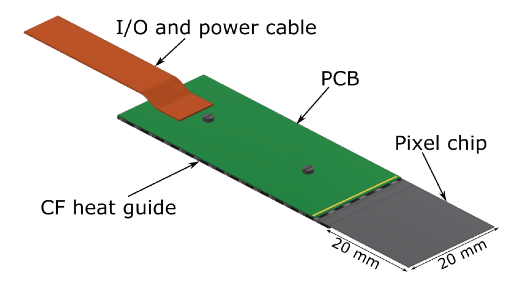
Due to the low momentum of the muons ( MeV), the spatial resolution of the detector will be dominated by multiple scattering effects and building the detector from minimum material will be crucial. The prototype detector uses a depleted monolithic active pixel sensor chip of the MuPix family as a sensitive element and all components needed for readout, power and cooling of the detector are placed outside the active area. The prototype detector is built from 34 modules with a total active area of 136 cm2. The radius of the inner and outer pixel layers are 21 mm and 31 mm, respectively. The detector acceptance determined for a sample of 100’000 simulated muons with an average momentum of 27 MeV is 56%.
The effect of multiple scattering on the resolution has been studied assuming a sensor thickness of 50m and was found to be about 0.65 mm at the muon decay point. The possibility of thinning the sensors to thicknesses of less than 50m is currently being studied. With thinner sensors with a thickness of 30m the resolution can be improved to less than 0.50 mm.
5 Conclusions
Two new high-intensity muon beams HIMB at PSI with up to two orders of magnitude higher and completely unprecedented intensities of surface muons will boost muon science in many ways. Flavour physics is a hot topic in particle physics, with charged lepton flavour searches and muon electromagnetic moment measurements in particular. Such experiments at HIMB will remain at the forefront of research for the next two decades or longer. Other fundamental atomic, nuclear and particle physics experiments will complement these flagship experiments, testing essentially all known interactions with considerable discovery potential for physics beyond the current Standard Model of particle physics. Likewise, in condensed matter physics HIMB will open up completely new regions of experimental phase space, for smaller sample sizes, for faster spatially and time-resolved measurements, and for depth profiling in so far inaccessible regions. All experiments at HIMB will considerably benefit from technological advances in detector technology, target technology and sample environment. Application of novel technologies, in particular of thin and fast tracking detectors and of new muon beam cooling schemes will further push the boundaries of what is presently possible in muon physics. The physics case for HIMB will continue to develop over time and lead to a definition of an initial physics program at this eagerly awaited new facility. The cases presented here already motivate a very strong and unique program for the next two decades.
Acknowledgements
The science case presented here is built on the work of numerous people over many years and is a true community effort. It is a pleasure to thank all our colleagues at PSI and the external users for their contributions and support. A special thank you goes to all speakers and other participants of the HIMB Science Case workshop of April 2021.
We gratefully acknowledge support by the Swiss National Science Foundation (SNF) through the grants PCEFP2_181198, PCEFP2_181117, PP00P2_176884, 200441, 197052, 197346; by the European Research Council (ERC) through CoG. 725039, 818053; by the European Union’s Horizon 2020 research and innovation programme through grant 858199; by the German Research Foundation (DFG) under Project WA 4157/1; and by the JSPS Core-to-Core Program, A. Advanced Research Networks JPJSCCA20180004 and JSPS KAKENHI Grant Number JP21H04991 (Japan).
References
- [1] Joachim Grillenberger et al. “The High Intensity Proton Accelerator Facility” In SciPost Phys. Proc. 5, 2021, pp. 002 DOI: 10.21468/SciPostPhysProc.5.002
- [2] “Particle Physics at PSI” In SciPost Phys. Proc. 5, 2021 DOI: 10.21468/SciPostPhysProc.5
- [3] A. Amato “Heavy-fermion systems studied by SR technique” In Rev. Mod. Phys. 69 American Physical Society, 1997, pp. 1119–1180 DOI: 10.1103/RevModPhys.69.1119
- [4] Elvezio Morenzoni et al. “Low-Energy Muons at PSI: Examples of Investigations of Superconducting Properties in Near-Surface Regions and Heterostuctures” In Proceedings of the International Symposium on Science Explored by Ultra Slow Muon (USM2013) DOI: 10.7566/JPSCP.2.010201
- [5] A. Amato et al. “Probing the ground state properties of iron-based superconducting pnictides and related systems by muon-spin spectroscopy” Superconductivity in Iron-Pnictides In Physica C: Superconductivity 469.9, 2009, pp. 606–613 DOI: 10.1016/j.physc.2009.03.017
- [6] R. Khasanov et al. “High pressure research using muons at the Paul Scherrer Institute” In High Pressure Research 36.2 Taylor & Francis, 2016, pp. 140–166 DOI: 10.1080/08957959.2016.1173690
- [7] Z. Guguchia “Unconventional Magnetism in Layered Transition Metal Dichalcogenides” In Condensed Matter 5.2, 2020 DOI: 10.3390/condmat5020042
- [8] Tian Shang et al. “Time-Reversal Symmetry Breaking in Re-Based Superconductors: Recent Developments” In Frontiers in Physics 9, 2021, pp. 270 DOI: 10.3389/fphy.2021.651163
- [9] Elena Graverini “Flavour anomalies: a review” In J. Phys. Conf. Ser. 1137.1, 2019, pp. 012025 DOI: 10.1088/1742-6596/1137/1/012025
- [10] Yasmine Amhis “Averages of b-hadron, c-hadron, and -lepton properties as of 2018” In Eur. Phys. J. C 81.3, 2021, pp. 226 DOI: 10.1140/epjc/s10052-020-8156-7
- [11] Oliver Fischer “Unveiling Hidden Physics at the LHC”, 2021 arXiv:2109.06065 [hep-ph]
- [12] B. Abi “Measurement of the Positive Muon Anomalous Magnetic Moment to 0.46 ppm” In Phys. Rev. Lett. 126, 2021, pp. 141801 DOI: 10.1103/PhysRevLett.126.141801
- [13] G.. Bennett “Final Report of the Muon E821 Anomalous Magnetic Moment Measurement at BNL” In Phys. Rev. D 73, 2006, pp. 072003 DOI: 10.1103/PhysRevD.73.072003
- [14] T. Aoyama “The anomalous magnetic moment of the muon in the Standard Model” In Phys. Rept. 887, 2020, pp. 1–166 DOI: 10.1016/j.physrep.2020.07.006
- [15] Lorenzo Calibbi et al. “Charged Lepton Flavour Violation: An Experimental and Theoretical Introduction” In Riv. Nuovo Cim. 41.2, 2018, pp. 71–174 DOI: 10.1393/ncr/i2018-10144-0
- [16] S. Weinberg “Baryon and Lepton Nonconserving Processes” In Phys.Rev.Lett. 43, 1979, pp. 1566–1570 DOI: 10.1103/PhysRevLett.43.1566
- [17] B. Grzadkowski et al. “Dimension-Six Terms in the Standard Model Lagrangian” In JHEP 1010, 2010, pp. 085 DOI: 10.1007/JHEP10(2010)085
- [18] Elizabeth. Jenkins et al. “Low-Energy Effective Field Theory below the Electroweak Scale: Operators and Matching” In JHEP 03, 2018, pp. 016 DOI: 10.1007/JHEP03(2018)016
- [19] Giovanni Pruna et al. “The decay in a systematic effective field theory approach with dimension 6 operators” In JHEP 10, 2014, pp. 014 DOI: 10.1007/JHEP10(2014)014
- [20] Andreas Crivellin et al. “Renormalisation-group improved analysis of processes in a systematic effective-field-theory approach” In JHEP 05, 2017, pp. 117 DOI: 10.1007/JHEP05(2017)117
- [21] Robert. Bernstein et al. “Charged Lepton Flavor Violation: An Experimenter’s Guide” In Phys. Rept. 532, 2013, pp. 27–64 DOI: 10.1016/j.physrep.2013.07.002
- [22] U. Bellgardt “Search for the Decay ” In Nucl. Phys. B 299, 1988, pp. 1–6 DOI: 10.1016/0550-3213(88)90462-2
- [23] A.. Baldini “Search for the lepton flavour violating decay with the full dataset of the MEG experiment” In Eur. Phys. J. C 76.8, 2016, pp. 434 DOI: 10.1140/epjc/s10052-016-4271-x
- [24] Wilhelm. Bertl “A Search for muon to electron conversion in muonic gold” In Eur. Phys. J. C 47, 2006, pp. 337–346 DOI: 10.1140/epjc/s2006-02582-x
- [25] A.. Baldini “The design of the MEG II experiment” In Eur. Phys. J. C 78.5, 2018, pp. 380 DOI: 10.1140/epjc/s10052-018-5845-6
- [26] K. Arndt “Technical design of the phase I Mu3e experiment” In Nucl. Instrum. Meth. A 1014, 2021, pp. 165679 DOI: 10.1016/j.nima.2021.165679
- [27] R. Abramishvili “COMET Phase-I Technical Design Report” In PTEP 2020.3, 2020, pp. 033C01 DOI: 10.1093/ptep/ptz125
- [28] L. Bartoszek “Mu2e Technical Design Report”, 2014 DOI: 10.2172/1172555
- [29] Gilberto Colangelo et al. “A theory vade mecum for PSI experiments” In SciPost Phys. Proc. 5, 2021, pp. 005 DOI: 10.21468/SciPostPhysProc.5.005
- [30] A. Blondel “Research Proposal for an Experiment to Search for the Decay ”, 2013 arXiv:1301.6113 [physics.ins-det]
- [31] Ivan Peric “A novel monolithic pixelated particle detector implemented in high-voltage CMOS technology” In Nucl. Instrum. Meth. A 582, 2007, pp. 876–885 DOI: 10.1016/j.nima.2007.07.115
- [32] Ivan Perić “High-voltage pixel detectors in commercial CMOS technologies for ATLAS, CLIC and Mu3e experiments” In Nucl. Instrum. Meth. A 731, 2013, pp. 131–136 DOI: 10.1016/j.nima.2013.05.006
- [33] N. Grefkes “Mu3e Final Focus Study”, 2021
- [34] Ann-Kathrin Perrevoort “Sensitivity Studies on New Physics in the Mu3e Experiment and Development of Firmware for the Front-End of the Mu3e Pixel Detector”, 2018 DOI: 10.11588/heidok.00024585
- [35] Ann-Kathrin Perrevoort “The Rare and Forbidden: Testing Physics Beyond the Standard Model with Mu3e” In SciPost Phys. Proc. 1, 2019, pp. 052 DOI: 10.21468/SciPostPhysProc.1.052
- [36] Wilhelm. Bertl “Search for the Decay ” In Nucl. Phys. B 260, 1985, pp. 1–31 DOI: 10.1016/0550-3213(85)90308-6
- [37] G.M. Pruna et al. “Fully differential NLO predictions for the rare muon decay” In Phys. Lett. B 765, 2017, pp. 280–284 DOI: 10.1016/j.physletb.2016.12.039
- [38] Sean Hughes “Background studies for the Mu3e experiment”
- [39] L. Paolozzi et al. “Characterization of the demonstrator of the fast silicon monolithic ASIC for the TT-PET project” In Journal of Instrumentation 14.02 IOP Publishing, 2019, pp. P02009–P02009 DOI: 10.1088/1748-0221/14/02/p02009
- [40] D. vom Bruch “Pixel Sensor Evaluation and Online Event Selection for the Mu3e Experiment”, 2017
- [41] Dorothea vom Bruch “Track and Vertex Reconstruction on GPUs for the Mu3e Experiment” In GPU Computing in High-Energy Physics, 2015 DOI: 10.3204/DESY-PROC-2014-05/13
- [42] Dorothea vom Bruch “Online Data Reduction using Track and Vertex Reconstruction on GPUs for the Mu3e Experiment” In EPJ Web Conf. 150, 2017, pp. 00013 DOI: 10.1051/epjconf/201715000013
- [43] Alexandr Kozlinskiy “Track reconstruction for the Mu3e experiment based on a novel Multiple Scattering fit” In EPJ Web Conf. 150, 2017, pp. 00005 DOI: 10.1051/epjconf/201715000005
- [44] Niklaus Berger et al. “A New Three-Dimensional Track Fit with Multiple Scattering” In Nucl. Instrum. Meth. A 844, 2017, pp. 135 DOI: 10.1016/j.nima.2016.11.012
- [45] A. Kozlinskiy et al. “A new track reconstruction algorithm for the Mu3e experiment based on a fast multiple scattering fit” In JINST 9.12, 2014, pp. C12012 DOI: 10.1088/1748-0221/9/12/C12012
- [46] S. Schenk “A fast vertex fit for the Mu3e experiment”, 2013
- [47] G. Aad “The ATLAS Fast TracKer system” In JINST 16, 2021, pp. P07006 DOI: 10.1088/1748-0221/16/07/P07006
- [48] Sebastian Dittmeier “The ATLAS Hardware Track Trigger design towards first prototypes” In PoS Vertex2019, 2020, pp. 049 DOI: 10.22323/1.373.0049
- [49] H. Leuschner “Mu3e- upgrade simulations for the Mu3e experiment”, 2019
- [50] MEG A… “The Search for with Sensitivity: The Upgrade of the MEG Experiment” In Symmetry 13, 2021, pp. 19 DOI: 10.3390/sym13091591
- [51] G.. Tassielli “The Drift Chamber of the MEG II experiment” In JINST 15.09, 2020, pp. C09051 DOI: 10.1088/1748-0221/15/09/C09051
- [52] G. Chiarello et al. “Application of the Cluster Counting/Timing techniques to improve the performances of high transparency Drift Chamber for modern HEP experiments” In JINST 12.07, 2017, pp. C07021 DOI: 10.1088/1748-0221/12/07/C07021
- [53] Giovanni. Tassielli “A proposal of a drift chamber for the IDEA experiment for a future e+e- collider” In PoS ICHEP2020, 2021, pp. 877 DOI: 10.22323/1.390.0877
- [54] G. Bencivenni et al. “An ultra-light cylindrical GEM detector as inner tracker at KLOE-2” In Nucl. Instrum. Meth. A 581, 2007, pp. 221–224 DOI: 10.1016/j.nima.2007.07.082
- [55] G. Bencivenni et al. “The micro-Resistive WELL detector: a compact spark-protected single amplification-stage MPGD” In JINST 10.02, 2015, pp. P02008 DOI: 10.1088/1748-0221/10/02/P02008
- [56] Bernhard Ketzer “A Time Projection Chamber for High-Rate Experiments: Towards an Upgrade of the ALICE TPC” In Nucl. Instrum. Meth. A 732, 2013, pp. 237–240 DOI: 10.1016/j.nima.2013.08.027
- [57] M. Ahmed “Search for the lepton family number nonconserving decay ” In Phys. Rev. D 65, 2002, pp. 112002 DOI: 10.1103/PhysRevD.65.112002
- [58] P.. Zyla “Review of Particle Physics” In PTEP 2020.8, 2020, pp. 083C01 DOI: 10.1093/ptep/ptaa104
- [59] Atsushi Oya et al. “Development of high-rate capable and ultra-low mass Resistive Plate Chamber with Diamond-Like Carbon”, 2021 arXiv:2109.13525 [physics.ins-det]
- [60] Naoki Tsuji et al. “Study on Granularity Optimization for ILD Hadron Calorimeter” In JPS Conf. Proc. 27, 2019, pp. 012015 DOI: 10.7566/JPSCP.27.012015
- [61] A. Schöning “MuPix and ATLASPix – Architectures and Results” In PoS Vertex2019, 2020, pp. 024 DOI: 10.22323/1.373.0024
- [62] Julian. Schwinger “On Quantum electrodynamics and the magnetic moment of the electron” In Phys. Rev. 73, 1948, pp. 416–417 DOI: 10.1103/PhysRev.73.416
- [63] P. Kusch et al. “The Magnetic Moment of the Electron” In Phys. Rev. 74.3, 1948, pp. 250 DOI: 10.1103/PhysRev.74.250
- [64] D. Hanneke et al. “New Measurement of the Electron Magnetic Moment and the Fine Structure Constant” In Phys. Rev. Lett. 100, 2008, pp. 120801 DOI: 10.1103/PhysRevLett.100.120801
- [65] Stefano Laporta “High-precision calculation of the 4-loop contribution to the electron g-2 in QED” In Phys. Lett. B 772, 2017, pp. 232–238 DOI: 10.1016/j.physletb.2017.06.056
- [66] Tatsumi Aoyama et al. “Theory of the Anomalous Magnetic Moment of the Electron” In Atoms 7.1, 2019, pp. 28 DOI: 10.3390/atoms7010028
- [67] Alexander Keshavarzi et al. “The of charged leptons, and the hyperfine splitting of muonium” In Phys. Rev. D101, 2020, pp. 014029 DOI: 10.1103/PhysRevD.101.014029
- [68] Sergey Volkov “Calculating the five-loop QED contribution to the electron anomalous magnetic moment: Graphs without lepton loops” In Phys. Rev. D 100.9, 2019, pp. 096004 DOI: 10.1103/PhysRevD.100.096004
- [69] Richard. Parker et al. “Measurement of the fine-structure constant as a test of the Standard Model” In Science 360, 2018, pp. 191 DOI: 10.1126/science.aap7706
- [70] Léo Morel et al. “Determination of the fine-structure constant with an accuracy of 81 parts per trillion” In Nature 588.7836, 2020, pp. 61–65 DOI: 10.1038/s41586-020-2964-7
- [71] T. Albahri “Measurement of the anomalous precession frequency of the muon in the Fermilab Muon experiment” In Phys. Rev. D 103, 2021, pp. 072002 DOI: 10.1103/PhysRevD.103.072002
- [72] T. Albahri “Magnetic Field Measurement and Analysis for the Muon Experiment at Fermilab” In Phys. Rev. A 103, 2021, pp. 042208 DOI: 10.1103/PhysRevA.103.042208
- [73] T. Albahri “Beam dynamics corrections to the Run-1 measurement of the muon anomalous magnetic moment at Fermilab” In Phys. Rev. Accel. Beams 24, 2021, pp. 044002 DOI: 10.1103/PhysRevAccelBeams.24.044002
- [74] J. Grange “Muon Technical Design Report”, 2015 arXiv:1501.06858 [physics.ins-det]
- [75] M. Abe “A New Approach for Measuring the Muon Anomalous Magnetic Moment and Electric Dipole Moment” In PTEP 2019.5, 2019, pp. 053C02 DOI: 10.1093/ptep/ptz030
- [76] T.. Gorringe et al. “Precision Muon Physics” In Prog. Part. Nucl. Phys. 84, 2015, pp. 73–123 DOI: 10.1016/j.ppnp.2015.06.001
- [77] Tatsumi Aoyama et al. “Complete Tenth-Order QED Contribution to the Muon ” In Phys. Rev. Lett. 109, 2012, pp. 111808 DOI: 10.1103/PhysRevLett.109.111808
- [78] Andrzej Czarnecki et al. “Refinements in electroweak contributions to the muon anomalous magnetic moment” [Erratum: Phys. Rev. D73, 119901 (2006)] In Phys. Rev. D67, 2003, pp. 073006 DOI: 10.1103/PhysRevD.67.073006
- [79] C. Gnendiger et al. “The electroweak contributions to after the Higgs boson mass measurement” In Phys. Rev. D88, 2013, pp. 053005 DOI: 10.1103/PhysRevD.88.053005
- [80] Michel Davier et al. “Reevaluation of the hadronic vacuum polarisation contributions to the Standard Model predictions of the muon and using newest hadronic cross-section data” In Eur. Phys. J. C77.12, 2017, pp. 827 DOI: 10.1140/epjc/s10052-017-5161-6
- [81] Alexander Keshavarzi et al. “Muon and : a new data-based analysis” In Phys. Rev. D97.11, 2018, pp. 114025 DOI: 10.1103/PhysRevD.97.114025
- [82] Gilberto Colangelo et al. “Two-pion contribution to hadronic vacuum polarization” In JHEP 02, 2019, pp. 006 DOI: 10.1007/JHEP02(2019)006
- [83] Martin Hoferichter et al. “Three-pion contribution to hadronic vacuum polarization” In JHEP 08, 2019, pp. 137 DOI: 10.1007/JHEP08(2019)137
- [84] M. Davier et al. “A new evaluation of the hadronic vacuum polarisation contributions to the muon anomalous magnetic moment and to ” [Erratum: Eur. Phys. J. C80, 410 (2020)] In Eur. Phys. J. C80.3, 2020, pp. 241 DOI: 10.1140/epjc/s10052-020-7792-2
- [85] Alexander Kurz et al. “Hadronic contribution to the muon anomalous magnetic moment to next-to-next-to-leading order” In Phys. Lett. B734, 2014, pp. 144–147 DOI: 10.1016/j.physletb.2014.05.043
- [86] Kirill Melnikov et al. “Hadronic light-by-light scattering contribution to the muon anomalous magnetic moment revisited” In Phys. Rev. D70, 2004, pp. 113006 DOI: 10.1103/PhysRevD.70.113006
- [87] Pere Masjuan et al. “Pseudoscalar-pole contribution to the : a rational approach” In Phys. Rev. D95.5, 2017, pp. 054026 DOI: 10.1103/PhysRevD.95.054026
- [88] Gilberto Colangelo et al. “Dispersion relation for hadronic light-by-light scattering: two-pion contributions” In JHEP 04, 2017, pp. 161 DOI: 10.1007/JHEP04(2017)161
- [89] Martin Hoferichter et al. “Dispersion relation for hadronic light-by-light scattering: pion pole” In JHEP 10, 2018, pp. 141 DOI: 10.1007/JHEP10(2018)141
- [90] Antoine Gérardin et al. “Lattice calculation of the pion transition form factor with Wilson quarks” In Phys. Rev. D100.3, 2019, pp. 034520 DOI: 10.1103/PhysRevD.100.034520
- [91] Johan Bijnens et al. “Short-distance constraints for the HLbL contribution to the muon anomalous magnetic moment” In Phys. Lett. B798, 2019, pp. 134994 DOI: 10.1016/j.physletb.2019.134994
- [92] Gilberto Colangelo et al. “Longitudinal short-distance constraints for the hadronic light-by-light contribution to with large- Regge models” In JHEP 03, 2020, pp. 101 DOI: 10.1007/JHEP03(2020)101
- [93] Thomas Blum et al. “The hadronic light-by-light scattering contribution to the muon anomalous magnetic moment from lattice QCD” In Phys. Rev. Lett. 124.13, 2020, pp. 132002 DOI: 10.1103/PhysRevLett.124.132002
- [94] Gilberto Colangelo et al. “Remarks on higher-order hadronic corrections to the muon ” In Phys. Lett. B735, 2014, pp. 90–91 DOI: 10.1016/j.physletb.2014.06.012
- [95] G Abbiendi “Letter of Intent: the MUonE project”, 2019 URL: https://cds.cern.ch/record/2677471
- [96] Pulak Banerjee “Theory for muon-electron scattering @ 10 ppm: A report of the MUonE theory initiative” In Eur. Phys. J. C 80.6, 2020, pp. 591 DOI: 10.1140/epjc/s10052-020-8138-9
- [97] Sz. Borsanyi “Leading hadronic contribution to the muon magnetic moment from lattice QCD” In Nature 593.7857, 2021, pp. 51–55 DOI: 10.1038/s41586-021-03418-1
- [98] Christoph Lehner et al. “Consistency of hadronic vacuum polarization between lattice QCD and the R-ratio” In Phys. Rev. D 101, 2020, pp. 074515 DOI: 10.1103/PhysRevD.101.074515
- [99] Andreas Crivellin et al. “Hadronic Vacuum Polarization: versus Global Electroweak Fits” In Phys. Rev. Lett. 125.9, 2020, pp. 091801 DOI: 10.1103/PhysRevLett.125.091801
- [100] Alexander Keshavarzi et al. “Muon and connection” In Phys. Rev. D 102.3, 2020, pp. 033002 DOI: 10.1103/PhysRevD.102.033002
- [101] Bogdan Malaescu et al. “Impact of correlations between and on the EW fit” In Eur. Phys. J. C 81.1, 2021, pp. 46 DOI: 10.1140/epjc/s10052-021-08848-9
- [102] Gilberto Colangelo et al. “Constraints on the two-pion contribution to hadronic vacuum polarization” In Phys. Lett. B 814, 2021, pp. 136073 DOI: 10.1016/j.physletb.2021.136073
- [103] M.. Achasov “Measurement of the process cross section with the SND detector at the VEPP-2000 collider in the energy region GeV” In JHEP 01, 2021, pp. 113 DOI: 10.1007/JHEP01(2021)113
- [104] Francisco Campanario et al. “Standard model radiative corrections in the pion form factor measurements do not explain the anomaly” In Phys. Rev. D 100.7, 2019, pp. 076004 DOI: 10.1103/PhysRevD.100.076004
- [105] En-Hung Chao et al. “Hadronic light-by-light contribution to from lattice QCD: a complete calculation” In Eur. Phys. J. C 81.7, 2021, pp. 651 DOI: 10.1140/epjc/s10052-021-09455-4
- [106] Martin Hoferichter et al. “Asymptotic behavior of meson transition form factors” In JHEP 05, 2020, pp. 159 DOI: 10.1007/JHEP05(2020)159
- [107] Johan Bijnens et al. “Short-distance HLbL contributions to the muon anomalous magnetic moment beyond perturbation theory” In JHEP 10, 2020, pp. 203 DOI: 10.1007/JHEP10(2020)203
- [108] Johan Bijnens et al. “The two-loop perturbative correction to the HLbL at short distances” In JHEP 04, 2021, pp. 240 DOI: 10.1007/JHEP04(2021)240
- [109] Marvin Zanke et al. “On the transition form factors of the axial-vector resonance and its decay into ” In JHEP 07, 2021, pp. 106 DOI: 10.1007/JHEP07(2021)106
- [110] Igor Danilkin et al. “A dispersive estimate of scalar contributions to hadronic light-by-light scattering” In Phys. Lett. B 820, 2021, pp. 136502 DOI: 10.1016/j.physletb.2021.136502
- [111] Gilberto Colangelo et al. “Short-distance constraints for the longitudinal component of the hadronic light-by-light amplitude: an update” In Eur. Phys. J. C 81.8, 2021, pp. 702 DOI: 10.1140/epjc/s10052-021-09513-x
- [112] Bob Holdom “Two U(1)’s and Epsilon Charge Shifts” In Phys. Lett. B 166, 1986, pp. 196–198 DOI: 10.1016/0370-2693(86)91377-8
- [113] Maxim Pospelov “Secluded U(1) below the weak scale” In Phys. Rev. D 80, 2009, pp. 095002 DOI: 10.1103/PhysRevD.80.095002
- [114] Chien-Yi Chen et al. “Implications of a light “dark Higgs” solution to the -2 discrepancy” In Phys. Rev. D 93.3, 2016, pp. 035006 DOI: 10.1103/PhysRevD.93.035006
- [115] Hooman Davoudiasl et al. “Tale of two anomalies” In Phys. Rev. D 98.7, 2018, pp. 075011 DOI: 10.1103/PhysRevD.98.075011
- [116] L. Darmé et al. “Invisible decays of axion-like particles: constraints and prospects” In JHEP 06, 2021, pp. 009 DOI: 10.1007/JHEP06(2021)009
- [117] M. Cadeddu et al. “Muon and electron g-2 and proton and cesium weak charges implications on dark Zd models” In Phys. Rev. D 104.1, 2021, pp. 011701 DOI: 10.1103/PhysRevD.104.L011701
- [118] Manuel. Buen-Abad et al. “Challenges for an axion explanation of the muon measurement”, 2021 arXiv:2104.03267 [hep-ph]
- [119] Luc Darmé et al. “Flavour anomalies and the muon from feebly interacting particles”, 2021 arXiv:2106.12582 [hep-ph]
- [120] Andrzej Czarnecki et al. “The Muon anomalous magnetic moment: A Harbinger for ’new physics”’ In Phys. Rev. D 64, 2001, pp. 013014 DOI: 10.1103/PhysRevD.64.013014
- [121] Dominik Stöckinger “Muon (g 2) and Physics Beyond the Standard Model” In Adv. Ser. Direct. High Energy Phys. 20, 2009, pp. 393–438 DOI: 10.1142/9789814271844˙0012
- [122] Andreas Crivellin et al. “Combined explanations of and implications for a large muon EDM” In Phys. Rev. D 98.11, 2018, pp. 113002 DOI: 10.1103/PhysRevD.98.113002
- [123] Rodolfo Capdevilla et al. “A No-Lose Theorem for Discovering the New Physics of at Muon Colliders”, 2021 arXiv:2101.10334 [hep-ph]
- [124] B. Ananthanarayan et al. “Top mass prediction from supersymmetric guts” In Phys. Rev. D 44, 1991, pp. 1613–1615 DOI: 10.1103/PhysRevD.44.1613
- [125] Marcela Carena et al. “Electroweak symmetry breaking and bottom - top Yukawa unification” In Nucl. Phys. B 426, 1994, pp. 269–300 DOI: 10.1016/0550-3213(94)90313-1
- [126] Jorge. Lopez et al. “Large in supergravity models” In Phys. Rev. D 49, 1994, pp. 366–372 DOI: 10.1103/PhysRevD.49.366
- [127] U. Chattopadhyay et al. “Probing supergravity grand unification in the Brookhaven g-2 experiment” In Phys. Rev. D 53, 1996, pp. 1648–1657 DOI: 10.1103/PhysRevD.53.1648
- [128] Athanasios Dedes et al. “Correlation of and in minimal supergravity” In Phys. Rev. Lett. 87, 2001, pp. 251804 DOI: 10.1103/PhysRevLett.87.251804
- [129] A. Djouadi et al. “, type leptoquarks at colliners” In Z. Phys. C 46, 1990, pp. 679–686 DOI: 10.1007/BF01560270
- [130] Debrupa Chakraverty et al. “A Nonsupersymmetric resolution of the anomalous muon magnetic moment” In Phys. Lett. B 506, 2001, pp. 103–108 DOI: 10.1016/S0370-2693(01)00419-1
- [131] Kingman Cheung “Muon anomalous magnetic moment and leptoquark solutions” In Phys. Rev. D 64, 2001, pp. 033001 DOI: 10.1103/PhysRevD.64.033001
- [132] Martin Bauer et al. “Minimal Leptoquark Explanation for the R , RK , and Anomalies” In Phys. Rev. Lett. 116.14, 2016, pp. 141802 DOI: 10.1103/PhysRevLett.116.141802
- [133] Estefania Coluccio et al. “, lepton flavor violation, and decays with leptoquarks: Correlations and future prospects” In Phys. Rev. D 95.5, 2017, pp. 055018 DOI: 10.1103/PhysRevD.95.055018
- [134] Andreas Crivellin et al. “Correlating to the Anomalous Magnetic Moment of the Muon via Leptoquarks” In Phys. Rev. Lett. 127.2, 2021, pp. 021801 DOI: 10.1103/PhysRevLett.127.021801
- [135] Andreas Crivellin et al. “Scalar Leptoquarks in Leptonic Processes” In JHEP 02, 2021, pp. 182 DOI: 10.1007/JHEP02(2021)182
- [136] Prasanta Das et al. “Anomalous magnetic moment of the muon in a composite model”, 2001 arXiv:hep-ph/0102242
- [137] Zhao-Hua Xiong et al. “Muon anomalous magnetic moment in technicolor models” In Phys. Lett. B 508, 2001, pp. 295–300 DOI: 10.1016/S0370-2693(01)00521-4
- [138] Seong Park et al. “Muon anomalous magnetic moment and the stabilized Randall-Sundrum scenario” In Phys. Lett. B 506, 2001, pp. 99–102 DOI: 10.1016/S0370-2693(01)00417-8
- [139] G.. Giudice et al. “Testing new physics with the electron g-2” In JHEP 11, 2012, pp. 113 DOI: 10.1007/JHEP11(2012)113
- [140] Radovan Dermisek et al. “Explanation of the Muon g-2 Anomaly with Vectorlike Leptons and its Implications for Higgs Decays” In Phys. Rev. D 88, 2013, pp. 013017 DOI: 10.1103/PhysRevD.88.013017
- [141] Adam Falkowski et al. “Vector-like leptons: Higgs decays and collider phenomenology” In JHEP 05, 2014, pp. 092 DOI: 10.1007/JHEP05(2014)092
- [142] Wolfgang Altmannshofer et al. “ theory of Higgs flavor violation and ” In Phys. Rev. D 94.9, 2016, pp. 095026 DOI: 10.1103/PhysRevD.94.095026
- [143] Kamila Kowalska et al. “Expectations for the muon g-2 in simplified models with dark matter” In JHEP 09, 2017, pp. 112 DOI: 10.1007/JHEP09(2017)112
- [144] Pere Arnan et al. “Generic Loop Effects of New Scalars and Fermions in , and a Vector-like Generation” In JHEP 06, 2019, pp. 118 DOI: 10.1007/JHEP06(2019)118
- [145] Andreas Crivellin et al. “Consequences of chirally enhanced explanations of for and ” In JHEP 07, 2021, pp. 135 DOI: 10.1007/JHEP07(2021)135
- [146] P.. Ferreira et al. “ in the 2HDM and slightly beyond – an updated view”, 2021 arXiv:2104.03367 [hep-ph]
- [147] Eung Chun et al. “Explaining anomalies in two Higgs doublet model with vector-like leptons” In JHEP 11, 2020, pp. 077 DOI: 10.1007/JHEP11(2020)077
- [148] Mariana Frank et al. “Muon anomalous magnetic moment in two-Higgs-doublet models with vectorlike leptons” In Phys. Rev. D 102.11, 2020, pp. 115034 DOI: 10.1103/PhysRevD.102.115034
- [149] Junjie Cao et al. “Lepton-Specific Two-Higgs Doublet Model: Experimental Constraints and Implication on Higgs Phenomenology” In Phys. Rev. D 80, 2009, pp. 071701 DOI: 10.1103/PhysRevD.80.071701
- [150] Alessandro Broggio et al. “Limiting two-Higgs-doublet models” In JHEP 11, 2014, pp. 058 DOI: 10.1007/JHEP11(2014)058
- [151] Lei Wang et al. “A light pseudoscalar of 2HDM confronted with muon g-2 and experimental constraints” In JHEP 05, 2015, pp. 039 DOI: 10.1007/JHEP05(2015)039
- [152] Victor Ilisie “New Barr-Zee contributions to in two-Higgs-doublet models” In JHEP 04, 2015, pp. 077 DOI: 10.1007/JHEP04(2015)077
- [153] Tomohiro Abe et al. “Lepton-specific two Higgs doublet model as a solution of muon anomaly” In JHEP 07, 2015, pp. 064 DOI: 10.1007/JHEP07(2015)064
- [154] Andreas Crivellin et al. “A perturbed lepton-specific two-Higgs-doublet model facing experimental hints for physics beyond the Standard Model” In Phys. Rev. Lett. 116.8, 2016, pp. 081801 DOI: 10.1103/PhysRevLett.116.081801
- [155] Andreas Crivellin et al. “ transitions in two-Higgs-doublet models” In JHEP 06, 2019, pp. 119 DOI: 10.1007/JHEP06(2019)119
- [156] Syuhei Iguro et al. “Probing flavor-violating solutions for the muon anomaly at Belle II” In JHEP 09, 2020, pp. 144 DOI: 10.1007/JHEP09(2020)144
- [157] Hong-Xin Wang et al. “muon anomaly and --philic Higgs doublet with a light CP-even component”, 2021 arXiv:2104.03242 [hep-ph]
- [158] Wei-Shu Hou et al. “Charged lepton flavor violation in light of Muon ”, 2021 arXiv:2107.14114 [hep-ph]
- [159] Timothy Chupp et al. “Electric dipole moments of atoms, molecules, nuclei, and particles” In Rev. Mod. Phys. 91.1, 2019, pp. 015001 DOI: 10.1103/RevModPhys.91.015001
- [160] G.. Bennett “An Improved Limit on the Muon Electric Dipole Moment” In Phys. Rev. D 80, 2009, pp. 052008 DOI: 10.1103/PhysRevD.80.052008
- [161] V. Andreev “Improved limit on the electric dipole moment of the electron” In Nature 562.7727, 2018, pp. 355–360 DOI: 10.1038/s41586-018-0599-8
- [162] R.Sekhar Chivukula et al. “A Composite Technicolor Standard Model of Quarks” In Nucl. Phys. B 292, 1987, pp. 93–108 DOI: 10.1016/0550-3213(87)90638-9
- [163] L.J. Hall et al. “Weak scale effective supersymmetry” In Phys. Rev. Lett. 65, 1990, pp. 2939–2942 DOI: 10.1103/PhysRevLett.65.2939
- [164] A.J. Buras et al. “Universal unitarity triangle and physics beyond the standard model” In Phys. Lett. B 500, 2001, pp. 161–167 DOI: 10.1016/S0370-2693(01)00061-2
- [165] G. D’Ambrosio et al. “Minimal flavor violation: An Effective field theory approach” In Nucl. Phys. B 645, 2002, pp. 155–187 DOI: 10.1016/S0550-3213(02)00836-2
- [166] Joel Butler “Highlights and Perspectives from the CMS Experiment” In 5th Large Hadron Collider Physics Conference, 2017 arXiv:1709.03006 [hep-ex]
- [167] Lucia Masetti “ATLAS results and prospects with focus on beyond the Standard Model” In Nucl. Part. Phys. Proc. 303-305, 2018, pp. 43–48 DOI: 10.1016/j.nuclphysbps.2019.03.009
- [168] R. Aaij “Differential branching fractions and isospin asymmetries of decays” In JHEP 06, 2014, pp. 133 DOI: 10.1007/JHEP06(2014)133
- [169] Roel Aaij “Test of lepton universality using decays” In Phys. Rev. Lett. 113, 2014, pp. 151601 DOI: 10.1103/PhysRevLett.113.151601
- [170] Roel Aaij “Angular analysis and differential branching fraction of the decay ” In JHEP 09, 2015, pp. 179 DOI: 10.1007/JHEP09(2015)179
- [171] Roel Aaij “Angular analysis of the decay using 3 fb-1 of integrated luminosity” In JHEP 02, 2016, pp. 104 DOI: 10.1007/JHEP02(2016)104
- [172] Vardan Khachatryan “Angular analysis of the decay from pp collisions at TeV” In Phys. Lett. B 753, 2016, pp. 424–448 DOI: 10.1016/j.physletb.2015.12.020
- [173] Ina Carli “Angular analysis of decay with the ATLAS detector” In PoS FPCP2017, 2017, pp. 043 DOI: 10.22323/1.304.0043
- [174] Albert Sirunyan “Measurement of angular parameters from the decay in proton-proton collisions at 8 TeV” In Phys. Lett. B 781, 2018, pp. 517–541 DOI: 10.1016/j.physletb.2018.04.030
- [175] R. Aaij “Test of lepton universality with decays” In JHEP 08, 2017, pp. 055 DOI: 10.1007/JHEP08(2017)055
- [176] “Combination of the ATLAS, CMS and LHCb results on the decays”, 2020
- [177] Roel Aaij “Branching fraction measurements of the rare and decays”, 2021 arXiv:2105.14007 [hep-ex]
- [178] Marcel Algueró et al. “ global fits after Moriond 2021 results” In 55th Rencontres de Moriond on QCD and High Energy Interactions, 2021 arXiv:2104.08921 [hep-ph]
- [179] Wolfgang Altmannshofer et al. “New Physics in Rare B Decays after Moriond 2021”, 2021 arXiv:2103.13370 [hep-ph]
- [180] Ashutosh Alok et al. “A unique discrimination between new physics scenarios in anomalies”, 2020 arXiv:2001.04395 [hep-ph]
- [181] T. Hurth et al. “Model independent analysis of the angular observables in and ” In Phys. Rev. D 103, 2021, pp. 095020 DOI: 10.1103/PhysRevD.103.095020
- [182] Marco Ciuchini et al. “Lessons from the angular analyses” In Phys. Rev. D 103.1, 2021, pp. 015030 DOI: 10.1103/PhysRevD.103.015030
- [183] Vincenzo Cirigliano et al. “Minimal flavor violation in the lepton sector” In Nucl. Phys. B 728, 2005, pp. 121–134 DOI: 10.1016/j.nuclphysb.2005.08.037
- [184] X.. He et al. “New Z-prime Phenomenology” In Phys. Rev. D 43, 1991, pp. 22–24 DOI: 10.1103/PhysRevD.43.R22
- [185] Robert Foot “New Physics From Electric Charge Quantization?” In Mod. Phys. Lett. A 6, 1991, pp. 527–530 DOI: 10.1142/S0217732391000543
- [186] Xiao-Gang He et al. “Simplest Z-prime model” In Phys. Rev. D 44, 1991, pp. 2118–2132 DOI: 10.1103/PhysRevD.44.2118
- [187] Giovanni Pruna “Leptonic CP violation in the charged sector and effective field theory approach” In PoS FPCP2017, 2017, pp. 016 DOI: 10.22323/1.304.0016
- [188] Andreas Crivellin et al. “Combined Explanations of , and Implications for a Large Muon EDM” In PoS ALPS2019, 2020, pp. 009 DOI: 10.22323/1.360.0009
- [189] Rebecca Chislett “The muon EDM in the g-2 experiment at Fermilab” In EPJ Web Conf. 118, 2016, pp. 01005 DOI: 10.1051/epjconf/201611801005
- [190] F… Farley et al. “A New method of measuring electric dipole moments in storage rings” In Phys. Rev. Lett. 93, 2004, pp. 052001 DOI: 10.1103/PhysRevLett.93.052001
- [191] A. Adelmann et al. “Compact storage ring to search for the muon electric dipole moment” In J. Phys. G 37, 2010, pp. 085001 DOI: 10.1088/0954-3899/37/8/085001
- [192] Hiromi Iinuma et al. “Three-dimensional spiral injection scheme for the g-2/EDM experiment at J-PARC” In Nucl. Instrum. Meth. A 832, 2016, pp. 51–62 DOI: 10.1016/j.nima.2016.05.126
- [193] A. Adelmann “Search for a muon EDM using the frozen-spin technique”, 2021 arXiv:2102.08838 [hep-ex]
- [194] GA Beer et al. “Enhancement of muonium emission rate from silica aerogel with a laser-ablated surface” In Progress of Theoretical and Experimental Physics 2014.9 Oxford University Press, 2014 DOI: 10.1093/ptep/ptu116
- [195] A. Antognini “Muonium emission into vacuum from mesoporous thin films at cryogenic temperatures” In Phys. Rev. Lett. 108, 2012, pp. 143401 DOI: 10.1103/PhysRevLett.108.143401
- [196] K.. Khaw et al. “Spatial confinement of muonium atoms” In Phys. Rev. A 94.2, 2016, pp. 022716 DOI: 10.1103/PhysRevA.94.022716
- [197] . Khaw “Towards next generation fundamental precision measurements with muons”, 2015 URL: https://www.research-collection.ethz.ch/handle/20.500.11850/102926
- [198] D Taqqu “Ultraslow Muonium for a Muon beam of ultra high quality” In Physics Procedia 17 Elsevier, 2011, pp. 216–223 DOI: 10.1016/j.phpro.2011.06.039
- [199] Klaus Kirch et al. “Testing antimatter gravity with muonium” In International Journal of Modern Physics: Conference Series 30, 2014, pp. 1460258 World Scientific DOI: 10.1142/S2010194514602580
- [200] Anna Soter et al. “Development of a cold atomic muonium beam for next generation atomic physics and gravity experiments” In SciPost Phys. Proc. SciPost, 2021, pp. 31 DOI: 10.21468/SciPostPhysProc.5.031
- [201] M Saarela et al. “Hydrogen isotope and 3He impurities in liquid 4He” In Journal of Low Temperature Physics 90.5 Springer, 1993, pp. 415–449 DOI: 10.1007/BF00681890
- [202] JM Marin et al. “Atomic and Molecular Hydrogen Impurities in Liquid 4 He” In Journal of Low Temperature Physics 110.1 Springer, 1998, pp. 205–211 DOI: 10.1023/A:1022599725388
- [203] Savely. Karshenboim “Precision physics of simple atoms: QED tests, nuclear structure and fundamental constants” In Phys. Rept. 422, 2005, pp. 1–63 DOI: 10.1016/j.physrep.2005.08.008
- [204] Claudia Frugiuele et al. “Current and future perspectives of positronium and muonium spectroscopy as dark sectors probe” In Phys. Rev. D 100.1, 2019, pp. 015010 DOI: 10.1103/PhysRevD.100.015010
- [205] André. Gomes et al. “Laboratory tests of Lorentz and symmetry with muons” In Phys. Rev. D 90 American Physical Society, 2014, pp. 076009 DOI: 10.1103/PhysRevD.90.076009
- [206] Savely. Karshenboim “A Constraint on antigravity of antimatter from precision spectroscopy of simple atoms” In Astron. Lett. 35, 2009, pp. 663 DOI: 10.1134/S1063773709100028
- [207] Klaus. Jungmann “Precision Muonium Spectroscopy” In Journal of the Physical Society of Japan 85.9, 2016, pp. 091004 DOI: 10.7566/JPSJ.85.091004
- [208] T. Prokscha et al. “The new muE4 beam at PSI: A hybrid-type large acceptance channel for the generation of a high intensity surface-muon beam” In Nucl. Instrum. Meth. A 595, 2008, pp. 317–331 DOI: 10.1016/j.nima.2008.07.081
- [209] P. Crivelli “The Mu-MASS (MuoniuM lAser SpectroScopy) experiment” In Hyperfine Interact. 239.1, 2018, pp. 49 DOI: 10.1007/s10751-018-1525-z
- [210] B. Ohayon “Precision measurement of the Lamb shift in Muonium”, 2021 arXiv:2108.12891 [physics.atom-ph]
- [211] Ben Ohayon et al. “Current status and prospects of muonium spectroscopy at PSI” In SciPost Phys. Proc. 5, 2021, pp. 029 DOI: 10.21468/SciPostPhysProc.5.029
- [212] S. Kanda et al. “New precise spectroscopy of the hyperfine structure in muonium with a high-intensity pulsed muon beam”, 2020 arXiv:2004.05862 [hep-ex]
- [213] Michael. Eides “Hyperfine Splitting in Muonium: Accuracy of the Theoretical Prediction” In Phys. Lett. B 795, 2019, pp. 113–116 DOI: 10.1016/j.physletb.2019.06.011
- [214] Cédric Delaunay et al. “Towards an independent determination of muon g-2 from muonium spectroscopy”, 2021 arXiv:2106.11998 [hep-ph]
- [215] Pavel Fadeev et al. “Revisiting spin-dependent forces mediated by new bosons: Potentials in the coordinate-space representation for macroscopic- and atomic-scale experiments” In Phys. Rev. A 99.2, 2019, pp. 022113 DOI: 10.1103/PhysRevA.99.022113
- [216] Yu.. Andreev “Constraints on New Physics in Electron from a Search for Invisible Decays of a Scalar, Pseudoscalar, Vector, and Axial Vector” In Phys. Rev. Lett. 126.21, 2021, pp. 211802 DOI: 10.1103/PhysRevLett.126.211802
- [217] V. Meyer et al. “Measurement of the Energy Interval in Muonium” In Phys. Rev. Lett. 84 American Physical Society, 2000, pp. 1136–1139 DOI: 10.1103/PhysRevLett.84.1136
- [218] Joseph Goodman “Statistical optics” John Wiley & Sons, 2015
- [219] Markus Oberthaler et al. “Inertial sensing with classical atomic beams” In Physical Review A 54.4 APS, 1996, pp. 3165 DOI: 10.1103/PhysRevA.54.3165
- [220] Ben McMorran et al. “Model for partial coherence and wavefront curvature in grating interferometers” In Physical Review A 78.1 APS, 2008, pp. 013601 DOI: 10.1103/PhysRevA.78.013601
- [221] D.. Webber “Measurement of the Positive Muon Lifetime and Determination of the Fermi Constant to Part-per-Million Precision” In Phys. Rev. Lett. 106, 2011, pp. 041803 DOI: 10.1103/PhysRevLett.106.079901
- [222] W. Fetscher et al. “Muon Decay: Complete Determination of the Interaction and Comparison with the Standard Model” In Phys. Lett. B 173, 1986, pp. 102–106 DOI: 10.1016/0370-2693(86)91239-6
- [223] N. Danneberg “Muon decay: Measurement of the transverse polarization of the decay positrons and its implications for the Fermi coupling constant and time reversal invariance” In Phys. Rev. Lett. 94, 2005, pp. 021802 DOI: 10.1103/PhysRevLett.94.021802
- [224] Wulf Fetscher “Muon Decay” In SciPost Phys. Proc. 5, 2021, pp. 006 DOI: 10.21468/SciPostPhysProc.5.006
- [225] A. Jodidio “Search for Right-Handed Currents in Muon Decay” [Erratum: Phys.Rev.D 37, 237 (1988)] In Phys. Rev. D 34, 1986, pp. 1967 DOI: 10.1103/PhysRevD.34.1967
- [226] A. Hillairet “Precision muon decay measurements and improved constraints on the weak interaction” In Phys. Rev. D 85, 2012, pp. 092013 DOI: 10.1103/PhysRevD.85.092013
- [227] R. Bayes “Experimental Constraints on Left-Right Symmetric Models from Muon Decay” In Phys. Rev. Lett. 106, 2011, pp. 041804 DOI: 10.1103/PhysRevLett.106.041804
- [228] J.. Bueno “Precise measurement of parity violation in polarized muon decay” In Phys. Rev. D 84, 2011, pp. 032005 DOI: 10.1103/PhysRevD.84.032005
- [229] D.. Forero et al. “Lepton flavor violation and non-unitary lepton mixing in low-scale type-I seesaw” In JHEP 09, 2011, pp. 142 DOI: 10.1007/JHEP09(2011)142
- [230] R. Alonso et al. “Muon conversion to electron in nuclei in type-I seesaw models” In JHEP 01, 2013, pp. 118 DOI: 10.1007/JHEP01(2013)118
- [231] André de Gouvêa et al. “Global Constraints on a Heavy Neutrino” In Phys. Rev. D 93.3, 2016, pp. 033005 DOI: 10.1103/PhysRevD.93.033005
- [232] J. Beacham “Physics Beyond Colliders at CERN: Beyond the Standard Model Working Group Report” In J. Phys. G 47.1, 2020, pp. 010501 DOI: 10.1088/1361-6471/ab4cd2
- [233] A.. Krasznahorkay “Observation of Anomalous Internal Pair Creation in Be8 : A Possible Indication of a Light, Neutral Boson” In Phys. Rev. Lett. 116.4, 2016, pp. 042501 DOI: 10.1103/PhysRevLett.116.042501
- [234] Prateek Agrawal “Feebly-Interacting Particles:FIPs 2020 Workshop Report”, 2021 arXiv:2102.12143 [hep-ph]
- [235] Martin Bauer et al. “Flavor probes of axion-like particles”, 2021 arXiv:2110.10698 [hep-ph]
- [236] R. Bayes “Search for two body muon decay signals” In Phys. Rev. D 91.5, 2015, pp. 052020 DOI: 10.1103/PhysRevD.91.052020
- [237] Apostolos Pilaftsis “Astrophysical and terrestrial constraints on singlet Majoron models” In Phys. Rev. D 49, 1994, pp. 2398–2404 DOI: 10.1103/PhysRevD.49.2398
- [238] M. Hirsch et al. “Majoron emission in muon and tau decays revisited” [Erratum: Phys.Rev.D 79, 079901 (2009)] In Phys. Rev. D 79, 2009, pp. 055023 DOI: 10.1103/PhysRevD.79.055023
- [239] Lorenzo Calibbi et al. “Looking forward to Lepton-flavor-violating ALPs”, 2020 arXiv:2006.04795 [hep-ph]
- [240] Xavier Garcia et al. “Bounds on majoron emission from muon to electron conversion experiments” In Phys. Rev. D 84, 2011, pp. 113010 DOI: 10.1103/PhysRevD.84.113010
- [241] J. Goldman “Light Boson Emission in the Decay of the ” In Phys. Rev. D 36, 1987, pp. 1543–1546 DOI: 10.1103/PhysRevD.36.1543
- [242] R.. Bolton “Search for Rare Muon Decays with the Crystal Box Detector” In Phys. Rev. D 38, 1988, pp. 2077 DOI: 10.1103/PhysRevD.38.2077
- [243] A.M. Baldini “Search for lepton flavour violating muon decay mediated by a new light particle in the MEG experiment” In Eur. Phys. J. C 80.9, 2020, pp. 858 DOI: 10.1140/epjc/s10052-020-8364-1
- [244] Christina. Kreisch et al. “Neutrino puzzle: Anomalies, interactions, and cosmological tensions” In Phys. Rev. D 101.12, 2020, pp. 123505 DOI: 10.1103/PhysRevD.101.123505
- [245] Jose Bernal et al. “The trouble with ” In JCAP 10, 2016, pp. 019 DOI: 10.1088/1475-7516/2016/10/019
- [246] N. Aghanim “Planck 2018 results. VI. Cosmological parameters” [Erratum: Astron.Astrophys. 652, C4 (2021)] In Astron. Astrophys. 641, 2020, pp. A6 DOI: 10.1051/0004-6361/201833910
- [247] Kun-Feng Lyu et al. “Self-interacting neutrinos: Solution to Hubble tension versus experimental constraints” In Phys. Rev. D 103.1, 2021, pp. 015004 DOI: 10.1103/PhysRevD.103.015004
- [248] A.. Lessa et al. “Revising limits on neutrino-Majoron couplings” In Phys. Rev. D 75, 2007, pp. 094001 DOI: 10.1103/PhysRevD.75.094001
- [249] Pulak Banerjee et al. “QED at NNLO with McMule” In SciPost Phys. 9, 2020, pp. 027 DOI: 10.21468/SciPostPhys.9.2.027
- [250] B. Pontecorvo “Mesonium and anti-mesonium” In Sov. Phys. JETP 6, 1957, pp. 429
- [251] V.W. Hughes et al. “Formation of Muonium and Observation of its Larmor Precession” In Phys. Rev. Lett. 5, 1960, pp. 63–65
- [252] J.J. Amato et al. “Search for muonium-antimuonium conversion” In Phys. Rev. Lett. 21, 1968, pp. 1709–1712
- [253] Glen. Marshall et al. “A Search for Muonium to Anti-muonium Conversion” In Phys. Rev. D 25, 1982, pp. 1174
- [254] T.M. Huber “Search for Mixing of Muonium () and Anti-muonium ()” In Phys. Rev. D 41, 1990, pp. 2709–2725
- [255] P.R. Bolton “Observation of Muonium in Vacuum” In Phys. Rev. Lett. 47, 1981, pp. 1441–1444 DOI: 10.1103/PhysRevLett.47.1441
- [256] B. Ni “Search for Spontaneous Conversion of Muonium to Antimuonium” In Phys. Rev. Lett. 59.24, 1987, pp. 2716–2719
- [257] B. Ni “Search for spontaneous conversion of muonium to anti-muonium” In Phys. Rev. D 48, 1993, pp. 1976–1989
- [258] B.E. Matthias “New search for the spontaneous conversion of muonium to anti-muonium” In Phys. Rev. Lett. 66, 1991, pp. 2716–2719
- [259] R. Abela “Improved upper limit on muonium to anti-muonium conversion” In Phys. Rev. Lett. 77, 1996, pp. 1950–1953 arXiv:nucl-ex/9805005
- [260] L. Willmann “New bounds from searching for muonium to anti-muonium conversion” In Phys. Rev. Lett. 82, 1999, pp. 49–52 arXiv:hep-ex/9807011
- [261] S. Agostinelli “GEANT4–a simulation toolkit” In Nucl. Instrum. Meth. A 506, 2003, pp. 250–303 DOI: 10.1016/S0168-9002(03)01368-8
- [262] A. Antognini et al. “Proton Structure from the Measurement of Transition Frequencies of Muonic Hydrogen” In Science 339, 2013, pp. 417–420 DOI: 10.1126/science.1230016
- [263] Randolf Pohl “Laser spectroscopy of muonic deuterium” In Science 353.6300, 2016, pp. 669–673 DOI: 10.1126/science.aaf2468
- [264] Julian. Krauth “Measuring the -particle charge radius with muonic helium-4 ions” In Nature 589.7843, 2021, pp. 527–531 DOI: 10.1038/s41586-021-03183-1
- [265] Frederik Wauters et al. “The project”, 2021 arXiv:2108.10765 [physics.ins-det]
- [266] John. Missimer et al. “The Neutral Weak Current of the Muon” In Phys. Rept. 118, 1985, pp. 179
- [267] K. Kirch et al. “Metastability of the Muonic Boron State” In Phys. Rev. Lett. 78 American Physical Society, 1997, pp. 4363–4366 DOI: 10.1103/PhysRevLett.78.4363
- [268] Savely. Karshenboim et al. “Constraints on muon-specific dark forces” [Addendum: Phys.Rev.D 90, 079905 (2014)] In Phys. Rev. D 90.7, 2014, pp. 073004 DOI: 10.1103/PhysRevD.90.073004
- [269] Andreas Crivellin et al. “First-generation new physics in simplified models: from low-energy parity violation to the LHC” In JHEP 10, 2021, pp. 221 DOI: 10.1007/JHEP10(2021)221
- [270] E.G. Kessler et al. “The GAMS4 flat crystal facility” In Nuclear Instruments and Methods in Physics Research Section A: Accelerators, Spectrometers, Detectors and Associated Equipment 457.1, 2001, pp. 187–202 DOI: https://doi.org/10.1016/S0168-9002(00)00753-1
- [271] Saskia Kraft-Bermuth et al. “Microcalorimeters for X-Ray Spectroscopy of Highly Charged Ions at Storage Rings” In Atoms 6.4, 2018, pp. 59 DOI: 10.3390/atoms6040059
- [272] R. Winkler et al. “256-pixel microcalorimeter array for high-resolution -ray spectroscopy of mixed-actinide materials” In Nuclear Instruments and Methods in Physics Research Section A: Accelerators, Spectrometers, Detectors and Associated Equipment 770, 2015, pp. 203–210 DOI: https://doi.org/10.1016/j.nima.2014.09.049
- [273] Nancy Paul et al. “Testing Quantum Electrodynamics with Exotic Atoms” In Phys. Rev. Lett. 126.17, 2021, pp. 173001 DOI: 10.1103/PhysRevLett.126.173001
- [274] Ryuichiro Kitano et al. “Detailed calculation of lepton flavor violating muon electron conversion rate for various nuclei” [Erratum: Phys.Rev.D 76, 059902 (2007)] In Phys. Rev. D 66, 2002, pp. 096002 DOI: 10.1103/PhysRevD.76.059902
- [275] A. Yaouanc et al. “Muon Spin Rotation, Relaxation, and Resonance: Applications to Condensed Matter” Oxford, UK: Oxford University Press, 2011
- [276] Donald. Fleming et al. “Kinetic Isotope Effects for the Reactions of Muonic Helium and Muonium with H2” In Science 331.6016 American Association for the Advancement of Science, 2011, pp. 448–450 DOI: 10.1126/science.1199421
- [277] F. Berg “Target Studies for Surface Muon Production” In Phys. Rev. Accel. Beams 19.2, 2016, pp. 024701 DOI: 10.1103/PhysRevAccelBeams.19.024701
- [278] Oren Shafir et al. “Demonstrating multibit magnetic memory in the high-spin molecule by muon spin rotation” In Phys. Rev. B 72 American Physical Society, 2005, pp. 092410 DOI: 10.1103/PhysRevB.72.092410
- [279] Lorenzo Tesi et al. “Isotope effects on the spin dynamics of single-molecule magnets probed using muon spin spectroscopy” In Chem. Commun. 54 The Royal Society of Chemistry, 2018, pp. 7826–7829 DOI: 10.1039/C8CC04703K
- [280] Evan Kiefl et al. “Robust Magnetic Properties of a Sublimable Single-Molecule Magnet” In ACS Nano 10, 2016, pp. 5663–5669 DOI: 10.1021/acsnano.6b01817
- [281] Ola Forslund et al. “Magnetic phase diagram of K2Cr8O16 clarified by high-pressure muon spin spectroscopy” In Scientific Reports 9, 2019, pp. 1141 DOI: 10.1038/s41598-018-37844-5
- [282] Tom Lancaster et al. “Another dimension: investigations of molecular magnetism using muon–spin relaxation” In Physica Scripta 88.6 IOP Publishing, 2013, pp. 068506 DOI: 10.1088/0031-8949/88/06/068506
- [283] Katherine Tustain et al. “From magnetic order to quantum disorder in the Zn-barlowite series of S = 1/2 kagomé antiferromagnets” In npj Quantum Materials 5, 2020, pp. 74 DOI: 10.1038/s41535-020-00276-4
- [284] Bin Gao et al. “Experimental signatures of a three-dimensional quantum spin liquid in effective spin-1/2 Ce2Zr2O7 pyrochlore” In Nature Physics 15, 2019, pp. 1052–1057 DOI: 10.1038/s41567-019-0577-6
- [285] Francis Pratt “Superconductivity and Magnetism in Organic Materials Studied with SR” In Journal of the Physical Society of Japan 85, 2016, pp. 091008 DOI: 10.7566/JPSJ.85.091008
- [286] Ke Wang et al. “Spintronic and Electronic Phenomena in Organic Molecules Measured with SR” In Journal of the Physical Society of Japan 85, 2016, pp. 091011 DOI: 10.7566/JPSJ.85.091011
- [287] F Pratt “Muon spin relaxation as a probe of electron motion in conducting polymers” In Journal of Physics: Condensed Matter 16, 2004, pp. S4779–S4796 DOI: 10.1088/0953-8984/16/40/019
- [288] Iain McKenzie et al. “Muoniated spin probes in the discotic liquid crystal HHTT: Rapid electron spin relaxation in the hexagonal columnar and isotropic phases” In Phys. Rev. E 87 American Physical Society, 2013, pp. 012504 DOI: 10.1103/PhysRevE.87.012504
- [289] Z. Guguchia et al. “Tunable anomalous Hall conductivity through volume-wise magnetic competition in a topological kagomé magnet” In Nature Communications 11, 2020, pp. 559 DOI: 0.1038/s41467-020-14325-w
- [290] Zurab Guguchia et al. “Nodeless superconductivity and its evolution with pressure in the layered dirac semimetal 2M-WS2” In npj Quantum Materials 4, 2019, pp. 50 DOI: 10.1038/s41535-019-0189-5
- [291] Jonas. Krieger et al. “Proximity-Induced Odd-Frequency Superconductivity in a Topological Insulator” In Phys. Rev. Lett. 125 American Physical Society, 2020, pp. 026802 DOI: 10.1103/PhysRevLett.125.026802
- [292] J.. Krieger et al. “Do topology and ferromagnetism cooperate at the interface?” In Phys. Rev. B 99 American Physical Society, 2019, pp. 064423 DOI: 10.1103/PhysRevB.99.064423
- [293] H.. Alberto et al. “Slow-muon study of quaternary solar-cell materials: Single layers and junctions” In Phys. Rev. Materials 2, 2018, pp. 025402 DOI: 10.1103/PhysRevMaterials.2.025402
- [294] M.A. Curado et al. “Front passivation of Cu(In,Ga)Se2 solar cells using Al2O3: Culprits and benefits” In Applied Materials Today 21, 2020, pp. 100867 DOI: 10.1016/j.apmt.2020.100867
- [295] Judith Woerle et al. “Interaction of low-energy muons with defect profiles in proton-irradiated Si and -SiC” In Phys. Rev. B 100, 2019, pp. 115202 DOI: 10.1103/PhysRevB.100.115202
- [296] J. Woerle et al. “Muon Interaction with Negative- and High-Spin-State Defects: Differentiating Between and Vacancies in -” In Phys. Rev. Applied 14 American Physical Society, 2020, pp. 054053 DOI: 10.1103/PhysRevApplied.14.054053
- [297] T. Prokscha et al. “Direct Observation of Hole Carrier-Density Profiles and Their Light-Induced Manipulation at the Surface of ” In Phys. Rev. Applied 14, 2020, pp. 014098 DOI: 10.1103/PhysRevApplied.14.014098
- [298] R. Abela et al. “Muons on request (MORE): Combining advantages of continuous and pulsed muon beams” In Hyperfine Interactions 120-121.1-8, 1999, pp. 575–578 DOI: 10.1023/A:1017046817431
- [299] A.. Pifer et al. “A High Stopping Density Beam” In Nucl. Instrum. Meth. 135, 1976, pp. 39–46 DOI: 10.1016/0029-554X(76)90823-5
- [300] T. Prokscha et al. “Depth dependence of the ionization energy of shallow hydrogen states in ZnO and CdS” In Physical Review B 90, 2014, pp. 235303 DOI: 10.1103/PhysRevB.90.235303
- [301] P. Bakule et al. “Generation and applications of slow polarized muons” In Contemp. Phys. 45, 2004, pp. 203 DOI: 10.1080/00107510410001676803
- [302] E. Morenzoni et al. “Nano-scale thin film investigations with slow polarized muons” In J. Phys.: Cond. Matt. 16, 2004, pp. S4583 DOI: 10.1088/0953-8984/16/40/010
- [303] Judith Woerle et al. “Low-Energy Muons as a Tool for a Depth-Resolved Analysis of the SiO2/4H-SiC Interface” Conference Name: Silicon Carbide and Related Materials 2019 Pages: 581-586 Volume: 1004 In Materials Science Forum, 2020 DOI: 10.4028/www.scientific.net/MSF.1004.581
- [304] Jun Sugiyama et al. “Li-ion diffusion in Li4Ti5O12 and LiTi2O4 battery materials detected by muon spin spectroscopy” In Physical Review B 92, 2015, pp. 014417 DOI: 10.1103/PhysRevB.92.014417
- [305] Jun Sugiyama “Spin polarized beam for battery materials research: and ” In Hyperfine Interactions 240, 2019, pp. 17 DOI: 10.1007/s10751-019-1560-4
- [306] Z. Salman et al. “Near-Surface Structural Phase Transition of SrTiO3 Studied with Zero-Field -Detected Nuclear Spin Relaxation and Resonance” In Phys. Rev. Lett. 96.14, 2006, pp. 147601 DOI: 10.1103/PhysRevLett.96.147601
- [307] K. Yokoyama et al. “Photoexcited Muon Spin Spectroscopy: A New Method for Measuring Excess Carrier Lifetime in Bulk Silicon” In Physical Review Letters 119, 2017, pp. 226601 DOI: 10.1103/PhysRevLett.119.226601
- [308] I. Belosevic “muCool: A next step towards efficient muon beam compression” In Eur. Phys. J. C 79.5, 2019, pp. 430 DOI: 10.1140/epjc/s10052-019-6932-z
- [309] A. Aqeel et al. “Probing current-induced magnetic fields in Au—YIG heterostructures with low-energy muon spin spectroscopy” In Applied Physics Letters 110, 2017, pp. 062409 DOI: 10.1063/1.4975487
- [310] T. Moorsom et al. “Reversible spin storage in metal oxide—fullerene heterojunctions” In Science Advances 6, 2020, pp. eaax1085 DOI: 10.1126/sciadv.aax1085
- [311] Lu Li et al. “Coexistence of magnetic order and two-dimensional superconductivity at LaAlO3/SrTiO3 interfaces” In Nature Physics 7, 2011, pp. 762–766 DOI: 10.1038/nphys2080
- [312] Julie. Bert et al. “Direct imaging of the coexistence of ferromagnetism and superconductivity at the LaAlO3/SrTiO3 interface” In Nature Physics 7, 2011, pp. 767–771 DOI: 10.1038/nphys2079
- [313] G.. Luke et al. “Time-reversal symmetry-breaking superconductivity in Sr2RuO4” In Nature 394, 1998, pp. 558–561 DOI: 10.1038/29038
- [314] Lin Jiao et al. “Chiral superconductivity in heavy-fermion metal UTe2” In Nature 579, 2020, pp. 523–527 DOI: 10.1038/s41586-020-2122-2
- [315] G. Janka et al. “Intense beam of metastable Muonium” In The European Physical Journal C 80, 2020, pp. 804 DOI: 10.1140/epjc/s10052-020-8400-1
- [316] Y. Miyake et al. “Ultra slow muon microscopy by laser resonant ionization at J-PARC, MUSE” In Hyperfine Interactions 216, 2013, pp. 79–83 DOI: 10.1007/s10751-012-0759-4
- [317] Takayuki Yamazaki et al. “Muon Cyclotron for Transmission Muon Microscope” In Proceedings of the 22nd International Conference on Cyclotrons and their Applications Cyclotrons2019, 2020 DOI: 10.18429/JACOW-CYCLOTRONS2019-TUP024
- [318] Luping Zhou et al. “Simulation studies for upgrading the surface muon beamline E4 at PSI”, 2021 arXiv:2108.04986 [physics.acc-ph]
- [319] E. Köhler et al. “Application of muonic X-ray techniques to the elemental analysis of archeological objects” In Nuclear Instruments and Methods in Physics Research 187, 1981, pp. 563–568 DOI: 10.1016/0029-554X(81)90389-X
- [320] H. Daniel “Application of X rays from negative muons” In Nuclear Instruments and Methods in Physics Research Section B: Beam Interactions with Materials and Atoms 3, 1984, pp. 65–70 DOI: 10.1016/0168-583X(84)90338-0
- [321] K Ninomiya et al. “Development of elemental analysis by muonic X-ray measurement in J-PARC” In Journal of Physics: Conference Series 225, 2010, pp. 012040 DOI: 10.1088/1742-6596/225/1/012040
- [322] A.. Hillier et al. “Probing beneath the surface without a scratch — Bulk non-destructive elemental analysis using negative muons” In Microchemical Journal 125, 2016, pp. 203–207 DOI: 10.1016/j.microc.2015.11.031
- [323] https://www.psi.ch/en/industry/news/tattoos-innovative-radiopharmaka-fur-die-theragnostik
- [324] J. Adam “The MEG detector for decay search” In Eur. Phys. J. C 73.4, 2013, pp. 2365 DOI: 10.1140/epjc/s10052-013-2365-2
- [325] D. Taqqu “Compression and extraction of stopped muons” In Phys. Rev. Lett. 97, 2006, pp. 194801 DOI: 10.1103/PhysRevLett.97.194801
- [326] W. Blum et al. “The Drift of Electrons and Ions in Gases”, 2008, pp. 1–48 DOI: 10.1007/978-3-540-76684-1˙2
- [327] Yu Bao “Muon cooling: longitudinal compression” In Phys. Rev. Lett. 112.22, 2014, pp. 224801 DOI: 10.1103/PhysRevLett.112.224801
- [328] A. Antognini “Demonstration of Muon-Beam Transverse Phase-Space Compression” In Phys. Rev. Lett. 125.16, 2020, pp. 164802 DOI: 10.1103/PhysRevLett.125.164802
- [329] Ivana Belosevic “Simulation and experimental verification of transverse and longitudinal compression of positive muon beams: Towards a novel high-brightness low-energy muon beam-line”, 2019 DOI: 10.3929/ethz-b-000402802
- [330] S. Bae “First muon acceleration using a radio frequency accelerator” In Phys. Rev. Accel. Beams 21.5, 2018, pp. 050101 DOI: 10.1103/PhysRevAccelBeams.21.050101
- [331] D. Schrage et al. “CW RFQ fabrication and engineering”, 1998 URL: https://www.osti.gov/biblio/335199
- [332] Colin Carlile et al. “European Spallation Source Technical Design Report”, 2013 DOI: 10.13140/RG.2.1.2040.6483/1
- [333] A. Antognini et al. “Studying Antimatter Gravity with Muonium” In Atoms 6.2, 2018, pp. 17 DOI: 10.3390/atoms6020017
- [334] S. Chatrchyan “The CMS Experiment at the CERN LHC” In JINST 3, 2008, pp. S08004 DOI: 10.1088/1748-0221/3/08/S08004
- [335] H.. Kastli “CMS barrel pixel detector overview” In Nucl. Instrum. Meth. A 582, 2007, pp. 724–727 DOI: 10.1016/j.nima.2007.07.058
- [336] W. Adam “The CMS Phase-1 Pixel Detector Upgrade” In JINST 16.02, 2021, pp. P02027 DOI: 10.1088/1748-0221/16/02/P02027
- [337] J.. Jungmann-Smith et al. “Towards hybrid pixel detectors for energy-dispersive or soft X-ray photon science” In Journal of Synchrotron Radiation 23.2, 2016, pp. 385–394 DOI: 10.1107/S1600577515023541
- [338] A. Bergamaschi et al. “The MÖNCH Detector for Soft X-ray, High-Resolution, and Energy Resolved Applications” In Synchrotron Radiation News 31.6 Taylor & Francis, 2018, pp. 11–15 DOI: 10.1080/08940886.2018.1528428
- [339] Aschkan Allahgholi et al. “The Adaptive Gain Integrating Pixel Detector at the European XFEL” In Journal of Synchrotron Radiation 26.1, 2019, pp. 74–82 DOI: 10.1107/S1600577518016077
- [340] Ch. Broennimann et al. “Development of an indium bump bond process for silicon pixel detectors at PSI” In Nucl. Instrum. Meth. A 565, 2006, pp. 303–308 DOI: 10.1016/j.nima.2006.05.011
- [341] Christopher. Kenney et al. “A Prototype monolithic pixel detector” In Nucl. Instrum. Meth. A 342, 1994, pp. 59–77 DOI: 10.1016/0168-9002(94)91411-7
- [342] R. Turchetta “A monolithic active pixel sensor for charged particle tracking and imaging using standard VLSI CMOS technology” In Nucl. Instrum. Meth. A 458, 2001, pp. 677–689 DOI: 10.1016/S0168-9002(00)00893-7