Adaptive Feedforward Reference Design for Active Vibration Rejection in Multi-Actuator Hard Disk Drives
Abstract
In December 2017, Seagate unveiled the Multi Actuator Technology to double the data performance of the future generation hard disk drives (HDD). This technology will equip drives with two dual stage actuators (DSA) each comprising of a voice coil motor (VCM) actuator and a piezoelectric micro actuator (MA) operating on the same pivot point. Each DSA is responsible for controlling half of the drive’s arms. As both the DSAs operate independently on the same pivot timber, the control forces and torques generated by one can affect the operation of the other and thereby worsening the performance drastically. In this paper, a robust adaptive feedforward controller is designed as an add-on controller to an existing stabilizing feedback controller to reject the disturbances transferred through the common pivot timber by shaping the references to the Voice Coil Motor (VCM) actuator and the total output of the dual stage system.
I Introduction
In the recent years, HDDs have been replaced by solid state drives (SSD) in most of personal computers regardless of their high cost. One of the most important reasons is that the data transfer rate of an SSD is much faster than that of an HDD. In 2017, Seagate unveiled its new multi actuator technology as a breakthrough that can double the data transfer performance of the future-generation hard drives for hyper-scale data centers. In a multi actuator drive, the read-write heads are split into two sets, an upper and a lower half, which can double the data transfer rate by having the upper and lower platter sets work in parallel.
The multi actuator setup brought some new challenges to the HDD’s controller design. Since both the DSAs operate on the same pivot point, the forces and torques generated by one actuator can affect the operation of the other DSA. The interaction of the two DSAs can be categorized into three basic scenarios. In the first scenario, both DSAs are in the track following mode, and it is expected that the interaction between the two actuators is negligible. In the second scenario, both the DSAs are in seek mode. In this mode, the coupling vibrational interaction is usually negligible compared to the large trajectories for both the DSAs. In the third scenario, one DSA is in seek mode and the other DSA is in track following mode. Under this scenario, the seeking DSA will impart disturbances in the form of vibration to the track following DSA, which drastically hamper the performance of the track following DSA.
A data-driven control design approach [16, 17] to suppress the vibrations generated by the seeking DSA has been applied to a multi actuator drive. The data-driven controllers are robust to the variations in the plant models. However, a common controller might not be the optimal controller for each individual HDD as there might be variations in the plants. To address this issue, an adaptive feedforward reference design technique is developed in this work. This work utilizes the reference design for track seeking controllers developed in [11] to shape the total output of the dual stage system. Since the track seeking architecture is already built inside the HDD, adding the current adaptive control strategy to the HDD would be simple. A pretraining strategy to prevent the MA’s output from exceeding its stroke limits during the adaptation process is also presented.
II Control Architectures for Dual Stage Actuators
II-A Feedback Control Structure
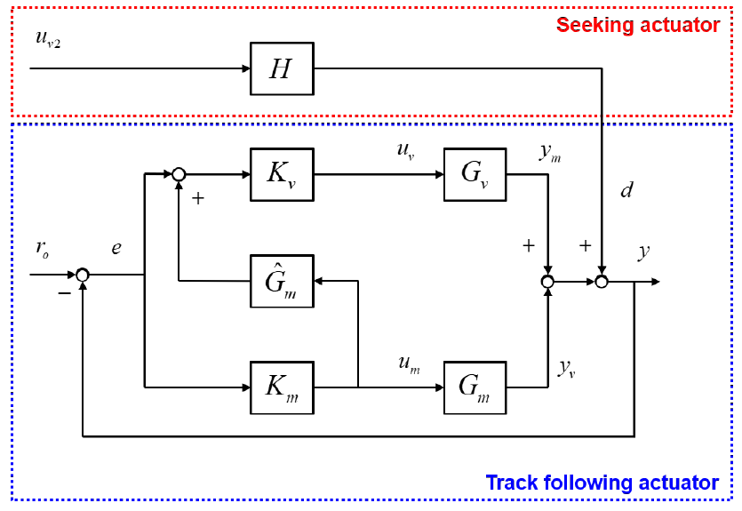
Fig.1 shows a block diagram of the dual-stage controller design using sensitivity decoupling method [9]. , represent the actual plants of the VCM and MA respectively. and are the Single-Input Single-Output (SISO) controllers for the VCM and MA plants respectively. is the feedforward plant estimate of MA. represents the disturbance cross transfer function from the seeking DSA to the track following DSA which takes in the input of the VCM of the track seeking DSA () and produces the disturbance on the output of the track following DSA. The signals represents the runout, represents the position error signal (PES), represents the control input to the VCM, represents the control input to the MA, represents the output of VCM, represents the output of MA, represents the total output produced by both the actuators and represents the actual output of the dual stage system along with the disturbance. The overall sensitivity transfer function from to can be calculated as
| (1) | ||||
| (2) |
where the modified MA plant is given by
| (3) |
The MA has high frequency uncertainties and hence the estimated model of the MA () is a good approximation of the actual MA plant () in the low frequency region. As a result will be very close to in those low frequency regions. In the high frequency regions, the term is relatively small as the VCM actuator is not active in that region. Consequently, any difference between and at high frequency regions will be decreased by the term and hence will also be a good approximation of at high frequency regions. Therefore, the overall sensitivity of the dual-stage actuation in 1 can be approximately decoupled as the multiplication of the actuators’ sensitivity transfer functions
| (4) |
where
| (5) |
| (6) |
II-B Feedforward Reference Design Structure
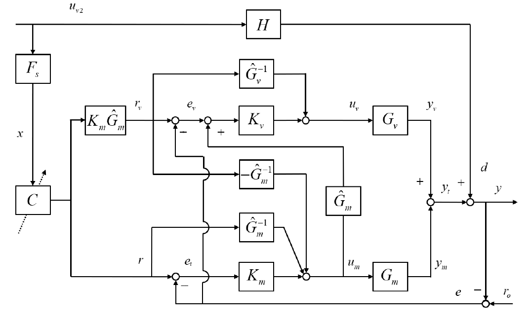
The feedback control structure for track following shown in the previous section has been extended to track seeking in [11]. In this structure, the reference trajectories to be followed by the read-write head of the DSA and the VCM actuator are designed to minimize the output of the MA as it has small stroke limits. Fig. 2 shows a block diagram of the feedforward reference design structure. In this structure, represents the estimate of the VCM plant. and are the Zero Phase plant inverses used in Zero Phase Error Tracking Control (ZPETC) [21]. The signals represents the reference signal to VCM and represents the reference to the total output of the dual stage system. The signals and .

Various signals and overall transfer functions can be easily obtained by simplifying the block diagram. Let and be the signals obtained by filtering the runout and disturbance signals through the sensitivity transfer function respectively. The PES in the presence of disturbance can be obtained from the block diagram as
| (7) |
where
| (8) |
| (9) |
Here denotes the transfer function from to and denotes the transfer function from to . If and , then is close to zero and is close to negative unity.
| (10) |
| (11) |
Furthermore, the PES can be approximated by
| (12) |
It can be seen that if the total reference signal is designed to be equal to , the PES can be minimized. To achieve this, the disturbance needs to be known. This motivates the design of an adaptive controller to estimate this signal.
III Adaptive Control Structure
In this section, an adaptive controller ’’ will be designed to estimate the signal and compensate for it. This design utilizes the feedforward reference design structure presented in the previous section. While estimating , it is also essential to respect the MA stroke limits and hence the references will be chosen in such a way that the MA’s output is minimized. The output of the MA can be obtained by simplifying the block diagram in fig. 2 as
| (13) |
Again, if and , the following approximation can be obtained for .
| (14) |
With the optimal filter , the reference signal follows the negative value of the filtered disturbance.
| (15) |
By substituting (15) in (III), and by designing as
| (16) |
we can obtain as
| (17) |
As the quantity is very small, the MA will just have to track which is well within its stroke limits. Similarly, we can also obtain the output of VCM, as
| (18) |
It can be seen that the VCM takes care of rejecting most of the actual disturbance as the signal explicitly appears in the expression for . The total output of the dual stage system can be obtained as
| (19) |
The actual output of the dual stage system along with the disturbance would now be
| (20) |
Having designed , the only task remaining is to make the reference signal as close to as possible. This is achieved using the control structure in fig.3. ’’ represents the adaptive controller and the filter is transfer function containing any known transfer functions. The signal is filtered through . We use an FIR filter with unknown coefficients to design . Any of the available parameter adaptation algorithms can be used to update the coefficients of . In our simulations, we used an Iterative Batch Least Squares (IBLS) approach developed in [22] to update the parameters of . This approach collects the signals and and formulates a least squares optimization problem which is then solved by a stochastic newton conjugate gradient method. The block diagram shown in fig.3 can be simplified to the block diagram shown in fig.4. From fig.4, we can obtain the overall transfer function of the secondary path as
| (21) |

Therefore we can define an estimate of as to be used in the parameter adaptation algorithm. The convergence condition for the parameters in the adaptive controller is stated in the following corollary.
Corollary 1: The controller converges to a unique stationary point if and only if is strictly positive real (SPR).
Controller Pretraining on the Single-Stage Actuator
As the MA has a stroke limit of only a few micrometers, the adaptive reference design should take into consideration the saturation properties of the PZT actuator during the entire parameter adaptation process. As discussed in the previous section, the output of the MA follows the opposite residual disturbance () and its absolute value remains small if the controller parameters are close to the stationary point. If the controller parameters are far from the optimal, the plant model of the MA becomes nonlinear and the parameter adaptation algorithm may diverge.
In order to get a good initial point for the adaptive controller in the dual-stage actuator system, the controller is pretrained on the single-stage actuator system with the VCM. The entire parameter adaptation process is then separated into two stages: a pretraining stage and a fine-tuning stage. In the pretraining stage, the MA is turned off. The controller parameters are initialized with some random points and updated on the single-stage actuator system until they converge. In the fine-tuning stage, the MA is turned on again. The controller parameters are tuned for the dual-stage actuator system on the most resent measurements.

The block diagram of the adaptive feedforward control system with a single-stage/dual-stage switching fashion is shown in fig.5. Comparing to the block diagram in fig.3, two switches are added. Switch 2 is used to turn on/off the MA, and switch 1 is used to adjust the transfer function of the secondary path such that the control parameters converge to the same stationary point both stages.
When the Switch 1 is on and Switch 2 is off, the system is running in the pretraining stage with a single-stage actuator. A simplifed block diagram is shown in fig.6. In fig.6 denotes the closed-loop sensitivity function of the single stage actuator, which is given by
| (22) |
denotes the transfer function from to , which is given by
| (23) |
If , then . The overall transfer function from to in a single-stage actuator system is given by
| (24) |

Recall that the overall transfer function from to in the dual-stage actuator system shown in fig.4 can be obtained as follows
| (25) |
If there exists a controller that perfectly cancels the imparted disturbance for a single-stage actuator system and make the transfer function equal to zero, then the transfer function is also close to zero. In other words, the optimal control for the single-stage actuator system is close to the optimal controller for the dual-stage actuator system. Therefore, the pretrained controller parameters would be good initial points for the finetuning stage, and the output of the MA is kept within its stroke limits during the entire parameter adaptation process.
IV Results
The adaptive feedforward reference design presented was numerically implemented with realistic plant models for VCM, MA, disturbance cross transfer function (shown in appendix) and order FIR filter for the adaptive controller. Fig. 7 shows the controller parameters in each iteration. Fig.8 shows the PES during the single-stage mode i.e., the pretraining stage. As only the VCM is turned on in this case, compensation is not very accurate, but the controller parameters converge to the optimal values. The converged parameters were used to initialize the controller parameters in the adaptation process for the dual-stage mode. Fig.9 shows the PES in the dual-stage mode which is within the desired limits.


V Conclusions
In this paper an adaptive feedforward control structure has been developed to learn and reject the disturbance process emanating from the dual stage actuator in the track seeking mode and affecting the dual stage actuator in the track following mode in a multi actuator hard disk drive. This control structure is designed as an add on controller to the already existing feedback control structure. The controller is designed as an FIR filter with unknown coefficients that are adapted to minimize the position error signal. A feedforward reference design structure has been used to make the adaptive controller robust to plant variations and to keep the output of the micro actuator within its stroke limits.
ACKNOWLEDGMENT
We would like to acknowledge the feedback and financial support from ASRC hosted by the International Disk Drive Equipment and Materials Association (IDEMA).
References
- [1] Jacob Benesty and Pierre Duhamel, "A fast exact least mean square adaptive algorithm", International Conference on Acoustics, Speech, and Signal Processing, IEEE, 1990, pp. 1457–1460.
- [2] Raghu Bollapragada, Richard H Byrd, and Jorge Nocedal, "Exact and inexact subsampled Newton methods for optimization", IMA Journal of Numerical Analysis 39.2 ,2019, pp. 545-578.
- [3] W.-K. Chen, Linear Networks and Systems (Book style). Belmont, CA: Wadsworth, 1993, pp. 123–135.
- [4] Richard H Byrd et al. "On the use of stochastic hessian information in optimization methods for machine learning", SIAM Journal on Optimization 21.3, 2011,pp. 977–995.
- [5] J Cio and Thomas Kailath, "Fast, recursive-least-squares transversal filters for adaptive filtering", IEEE Transactions on Acoustics, Speech, and Signal Processing 32.2, 1984, pp. 304–337.
- [6] Monson H Hayes, "9.4: Recursive least squares", Statistical Digital Signal Processing and Modeling, 1996, p. 541.
- [7] Simon Haykin and Bernard Widrow, "Least-mean-square adaptive filters", Vol. 31. John Wiley & Sons, 2003.
- [8] Simon S Haykin, "Adaptive filter theory", Pearson Education India, 2008.
- [9] Roberto Horowitz et al, "Dual-stage servo systems and vibration compensation in computer hard disk drives", Control Engineering Practice 15.3, 2007, pp. 291-305.
- [10] Xinghui Huang, Ryozo Nagamune, and Roberto Horowitz, "A comparison of multirate robust track-following control synthesis techniques for dual-stage and multisensing servo systems in hard disk drives", IEEE Transactions on magnetics 42.7, 2006, pp. 1896–1904.
- [11] Masahito Kobayashi and Roberto Horowitz, "Track seek control for hard disk dualstage servo systems", IEEE transactions on magnetics 37.2, 2001, pp. 949–954.
- [12] Yunfeng Li and Roberto Horowitz, "Mechatronics of electrostatic microactuators for computer disk drive dual-stage servo systems", IEEE/ASME transactions on mechatronics 6.2, 2001, pp. 111–121.
- [13] Lennart Ljung, "Analysis of recursive stochastic algorithms", IEEE transactions on automatic control 22.4, 1977, pp. 551–575.
- [14] S Shankar Narayan and AM Peterson, "Frequency domain least-mean-square algorithm", Proceedings of the IEEE 69.1, 1981, pp. 124–126.
- [15] F Roosta-Khorasani and MW Mahoney, "Sub-sampled Newton methods 1: Globally convergent algorithms ", 2006, arXiv preprint arXiv:1601.04737.
- [16] Prateek Shah, "Joint Feedback Feedforward Data Driven Control Design and Input Shaping Techniques for Multi Actuator Hard Disk Drives", PhD thesis, UC Berkeley, 2020.
- [17] Prateek Shah and Roberto Horowitz,"Active Vibration Rejection in Multi Actuator Drives: Data Driven Approach", Dynamic Systems and Control Conference, Vol. 59162, American Society of Mechanical Engineers, 2019, V003T17A002.
- [18] Behrooz Shahsavari, Jinwen Pan, and Roberto Horowitz, "Adaptive rejection of periodic disturbances acting on linear systems with unknown dynamics", IEEE 55th Conference on Decision and Control (CDC), IEEE, 2016, pp. 1243–1248.
- [19] Behrooz Shahsavari et al. "Adaptive repetitive control design with online secondary path modeling and application to bit-patterned media recording", IEEE Transactions on Magnetics 51.4, 2015, pp. 1–8.
- [20] Behrooz Shahsavari et al, "Adaptive repetitive control using a modified filltered-x lms algorithm", Dynamic Systems and Control Conference, Vol. 46186, American Society of Mechanical Engineers, 2014, V001T13A006.
- [21] Masayoshi Tomizuka, "Zero phase error tracking algorithm for digital control", 1987.
- [22] Zhi Chen, "Feedforward Learning Control For Multi Actuator Hard Drives and Freeform 3D Printers", PhD Thesis, UC Berkeley, 2021.
- [23] MATLAB. version 9.10.0 (R2016b). Natick, Massachusetts: The MathWorks Inc., 2016.
Appendix


