A chip-based superconducting magnetic trap for levitating superconducting microparticles
Abstract
Magnetically-levitated superconducting microparticles have been recently proposed as a promising platform for performing quantum experiments with particles in the picogram regime. Here, we demonstrate the superconducting technology to achieve chip-based magnetic levitation of superconducting microparticles. We simulate and fabricate a chip-based magnetic trap capable of levitating superconducting particles with diameters from 0.5m to 200m. The trap consists of two stacked silicon chips, each patterned with a planar multi-winding superconducting coil made of niobium. The two coils generate a magnetic field resembling a quadrupole near the trap center, in which we demonstrate trapping of a spherical 50 m diameter SnPb microparticle at temperatures of 4 K and 40 mK.
I Introduction
Superconducting levitation is a well known phenomenon and allows levitation of objects of vastly different masses Moon and Chang 1994. In the context of quantum experiments with macroscopic objects Arndt and Hornberger 2014, superconducting levitation can enable a novel experimental platform combining ultra-low mechanical dissipation of levitated particles Delić et al. 2020; Leng et al. 2021; Tebbenjohanns et al. 2021; Magrini et al. 2021 with the capability to stably trap micrometer-sized objects Romero-Isart et al. 2012; Cirio et al. 2012. Theoretical proposals to realize macroscopic quantum superposition states Pino et al. 2018, as well as novel ultra-sensitive force and acceleration sensors Johnsson et al. 2016; Prat-Camps et al. 2017, have recently been put forward that exploit these unique features.
Recent experiments have shown initial steps in this direction by levitating micro-magnets on top of superconductors Niemetz et al. 2000; Wang et al. 2019; Timberlake et al. 2019; Vinante et al. 2020; Gieseler et al. 2020, diamagnetic particles in strong magnetic fields Slezak et al. 2018; Zheng et al. 2020; Leng et al. 2021, and superconducting microparticles in millimeter-sized superconducting magnetic traps van Waarde 2016; Hofer et al. 2021. Levitating a superconducting particle in a fully chip-based, microfabricated trap is advantageous as it enables high magnetic field gradients through miniaturization Fortágh and Zimmermann 2007; Dikovsky et al. 2009 and a straightforward integration of precisely positioned superconducting circuits for read-out and quantum control of the particle’s motion Romero-Isart et al. 2012; Cirio et al. 2012; Johnsson et al. 2016; Pino et al. 2018.
In our work, we demonstrate a fully chip-based superconducting levitation platform. We discuss the design, simulation, and fabrication of our trap, and we use this trap in a proof-of-principle demonstration of levitating a 50m-diameter superconducting particle. We base the design of our trap on recent theoretical work in which different magnetic trap architectures were analyzed Romero-Isart et al. 2012; Cirio et al. 2012; Hofer and Aspelmeyer 2019; Latorre et al. 2020; Navau et al. 2021.
II Chip-based superconducting magnetic trap
II.1 Levitation requirements
In order to stably levitate a diamagnetic particle, first, a three-dimensional magnetic field minimum is required to confine it Simon and Geim 2000; Latorre et al. 2020. The magnetic field distribution used to achieve such a confinement resembles that of an anti-Helmholtz coil configuration. At the levitation point, the magnetic force balances Earth’s gravity. Second, to initially lift the particle off the substrate, the magnetic lift force must also overcome adhesive forces between the particle and the substrate. From a simulation of our trap, we expect a lift force of 19 nN on a 50 m-diameter superconducting sphere in the Meissner state when we apply a current of 0.5 A through the coils. This force greatly exceeds the particle’s weight (0.5 nN) and is, for certain particle-substrate interfaces, sufficient to overcome adhesive forces in our experiments. Note that these forces can be as large as 2 N for a 50 m metal sphere separated by 0.3 nm from a flat surface Alvo et al. 2010.
II.2 Design and simulation of the magnetic trap


The chip-based trap (see Fig. 1) consists of two multi-winding planar superconducting coils microfabricated on two silicon chips, which are stacked on top of each other. The coil separation is given by the 280 m thickness of one silicon chip. Each coil has ten windings with m spacing, and each winding has a rectangular cross-section with m width and m thickness. The coils are made of niobium and can carry a maximal current of 0.9 A at 4 K, limited by the critical current density of niobium (3 Hudson and Jirberg 1971). The coil dimensions are chosen as a trade-off between the magnetic field strength and the microfabrication yield: Narrower windings with smaller spacing can allow for a stronger magnetic field, due to the dependence of critical current density Hudson and Jirberg 1971 and current uniformity Il’in et al. 2010; Talantsev et al. 2018 on cross-section. However, millimeter-long narrow wires frequently detach from the substrate or break during assembly when their height to width ratio exceeds about .
To simulate the particle in the trap, we account for the three-dimensional geometry of the coils and the particle. We do this because the sample is not symmetric, thus, planar or rotationally symmetric two-dimensional models fail to capture its behavior, and also because the particle perturbs the trap field due to field expulsion Lin 2006; Hofer and Aspelmeyer 2019; Latorre et al. 2020. We calculate the magnetic field distribution from finite element method simulations using COMSOL Multiphysics COMSOL AB, Stockholm, Sweden 2019. The simulations operate in the static regime and are based on the A-V formulation of the Maxwell-London equations Campbell 2011, for details see Ref. Latorre et al. 2020. The simulations yield the magnetic field (shown in Fig. 2), magnetic force and supercurrents. We assume that the particle is in the Meissner state and model it via the Maxwell-London equations in A-V formulation Latorre et al. 2020. This situation holds when the particle is cooled below its critical temperature in zero field, and if the field near the particle stays below the first critical field of the material that the particle is made of, as is the case in our experiment. The coils are made of a type-II superconductor; we capture this in the model assuming a nearly-perfectly diamagnetic material (relative permeability ) with a high electrical conductivity for the coils, as described in Ref. Talantsev et al. 2018. Hence, our model assumes that (i) the particle is in the Meissner state, and (ii) that there is no trapped flux in the levitated particle, inside the coil wire or inside the coil windings. Trapped flux would affect the levitation height, trap frequencies and mechanical dissipation.
Fig. 2 shows the trapping magnetic field, with a three-dimensional field minimum between the coils. The particle’s equilibrium position is slightly shifted along the axis due to gravity, and along the axis due to the openings of the coils.
The simulated magnetic field allows us to estimate the trapped particle’s centre-of-mass (COM) motional frequencies: We calculate the restoring force acting on the particle when it is shifted by a small distance from its equilibrium position Latorre et al. 2020. In this way, we obtain motional frequencies for a 50 m particle, when 0.5 A current is passed through the coils (error is simulation uncertainty, see Ref. Latorre et al. 2020). These frequencies are much lower than the frequencies of typical micro- and nanomechanical resonators used in quantum experiments Aspelmeyer et al. 2014. As a consequence, if the motional modes are in thermal states they will have around () phonons at 4 K (10 mK). Thus, in order for the levitated particle to be in its COM motional ground state additional cooling techniques, such as feedback Tebbenjohanns et al. 2021; Magrini et al. 2021 or sideband cooling Chan et al. 2011; Teufel et al. 2011, are required.
The magnetic trap can be used to levitate particles of a huge range of diameters; the lower limit depends on the London penetration depth, , and the upper limit depends on the first critical field strength of the particle, , or is given by the geometry of the trap. For example, SnPb particles with diameters from 500 nm to 220 m could be levitated in our chip-based trap (assuming and Tsui et al. 2016; Lock 1951, when using a trap current of 0.5 A).
II.3 Fabrication
The chip trap is fabricated using conventional microfabrication techniques: The substrate is a double-side-polished, 280m-thick, two-inch undoped silicon wafer with (100) orientation. A m-thick Nb layer is deposited on the wafer by DC magnetron sputtering. The wafer is then diced into 7 mm7 mm chips with a Loadpoint Microace 3+ saw. The design for the magnetic trap is transferred to the Nb layer using electron beam lithography (Raith EBPG 5200) and reactive ion etching (Oxford Plasmalab 100). We etch a cylindrical hole into the top chip using the Bosch process with an STS ICP deep silicon etch system. The two chips are manually aligned using an optical microscope, and glued together using cryogenic GE-varnish. The top and bottom coils are electrically connected by wire bonding with a 25m diameter niobium wire as described in Ref. Jaszczuk et al. 1991; this ensures a superconducting connection between the coils at temperatures below 9 K. Finally, a single particle is placed within the etched hole using a Signatone SE-10T tungsten tip attached to a xyz translation stage.
III Superconducting microparticles
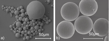
We use spherical microparticles made of lead (Pb) or a tin-lead alloy (Sn63Pb37), shown in Fig. 3, since lead and tin-lead have critical temperatures higher than 4 K (6.4 K and 7.0 K, respectively). Additionally, they have relatively high first critical field strengths (40 mT and 80 mT respectively Chanin and Torre 1972). We determined all these values, except for the critical field of lead, using AC magnetic susceptibility measurements.
The Pb microparticles are made in-house using ultrasonic cavitation Friedman et al. 2010, which yields near-spherical particles with a distribution of diameters between m and m. The tin-lead microspheres of 50m diameter are commercially available (EasySpheres).
IV Experimental setup
The chip trap is placed in a dilution refrigerator, which has a viewport that provides optical access to the sample stage. We use a custom-made microscope employing Köhler illumination to monitor the particle on a CMOS camera.

The trap current is supplied by an external current source, that passes through both pre-installed and custom-made wiring, as shown in Fig. 4. It is crucial to thermalize the wiring at each stage, to minimize the heat load at the sample stage. Pre-installed copper wires transport the current from room temperature to the 50 K stage, then a pre-installed superconducting BSCCO tape transports the current to the 4 K stage. At the 4 K stage the BSCCO tape terminates in gold-plated copper connectors, to which we clamp a copper-clad, formvar insulated, 190 m twisted NbTi wire pair, which transports the current to the sample stage. At the sample stage, the NbTi wire is clamped to bulky Nb bond pads on the sample holder. At either end where the NbTi cable is clamped, the insulation and the cladding are removed to ensure a superconducting connection. The NbTi wire is wound and glued with GE-varnish around copper bobbins, which are attached to different stages for thermalization, as shown in Fig. 4. The chip trap contains microfabricated Nb bond pads [see Fig. 1(c)], which are electrically connected to the bulky Nb bond pads on the sample holder via 25m-diameter Nb wire bonds.
The sample is magnetically shielded (Fig. 4) by two open-top baskets made of layers of superconducting and ferromagnetic material: the sample holder lies within a shield made of niobium and Cryoperm, and the entire sample stage lies within a shield made of lead, aluminium and mu-metal.
V Demonstration of magnetic levitation
In Fig. 5 we show images of a SnPb particle in the magnetic trap at a temperature of 4 K (see also video material Latorre et al. 2022). When we apply sufficient current to the trap, the particle levitates. This is evidenced by a sudden change of the particle position from its initial rest position [Fig. 5(a)], additionally the particle becomes blurred because of its oscillatory motion about the trap center [Fig. 5(b)]. The motional amplitude is strongly damped after 1 s [Fig. 5(c)]. After about 10 s the continuous illumination causes superconductivity to break and as a result the particle falls down [Fig. 5(d)]. When we do not shine light on the particle, we can levitate it for several days. We observe similar levitation results when using pure lead microparticles and also when the trap is operated at 40 mK (see also video material Latorre et al. 2022).
We extract the particle’s motional frequencies from an analysis of the levitation video. To this end, we determine the time-dependent particle center by fitting an ellipse to the particle images and identify the center position of the ellipse with the position of the particle in the plane. A Fourier transform of this time-dependent position yields the data in Fig. 6. We can clearly identify two dominant frequency components and attribute these to the COM motional modes along the and direction, Hz, respectively. The frequencies are in good agreement with the simulation results of . We attribute the small discrepancy to the spatial misalignment between the bottom and top coils, as is visible in Fig. 5.
VI Conclusion and outlook
We have presented the design, simulation and fabrication of a chip-based superconducting magnetic trap for levitating superconducting microparticles of diameters between 0.5m and 200m. We have demonstrated stable levitation of 50 m-diameter superconducting particles in this trap at temperatures of 4 K and 40 mK. In the future, we will lower the particle’s motional dissipation rate by using a DC-SQUID magnetometer to detect the particle motion non-invasively and by improving the magnetic field shielding. These are crucial steps to eventually bring the particle’s COM motion into the quantum regime. Note that in an independent recent experiment, chip-based superconducting magnetic levitation of a superconducting microparticle has also been realized Minniberger and Trupke 2021.
Acknowledgements.
We thank Thilo Bauch and Avgust Yurgens for insightful discussions. Further, we appreciate fruitful discussions with Joachim Hofer, Philip Schmidt, Stefan Minniberger, Michael Trupke, Markus Aspelmeyer and the other members of the EU Horizon 2020 project MaQSens. We are thankful for initial microfabrication support from David Niepce. We acknowledge funding from the Knut and Alice Wallenberg foundation through a Wallenberg Academy fellowship (W.W.), the Wallenberg Center for Quantum Technology (WACQT, A.P.) and support from Chalmers Excellence Initiative Nano. G.H. acknowledges support from the Swedish Research Council (grant no. 2020-00381). Sample fabrication was performed in the Myfab Nanofabrication Laboratory at Chalmers. Simulations were performed on resources provided by the Swedish National Infrastructure for Computing (SNIC) at Tetralith, Linköping University, partially funded by the Swedish Research Council through Grant No. 2018-05973.References
- Moon and Chang (1994) F. Moon and P. Chang, Superconducting Levitation: Applications to Bearings and Magnetic Transportation, A Wiley interscience publication (Wiley, 1994).
- Arndt and Hornberger (2014) M. Arndt and K. Hornberger, Testing the limits of quantum mechanical superpositions, Nature Physics 10, 271 (2014).
- Delić et al. (2020) U. Delić, M. Reisenbauer, K. Dare, D. Grass, V. Vuletić, N. Kiesel, and M. Aspelmeyer, Cooling of a levitated nanoparticle to the motional quantum ground state, Science 367, 892 (2020).
- Leng et al. (2021) Y. Leng, R. Li, X. Kong, H. Xie, D. Zheng, P. Yin, F. Xiong, T. Wu, C.-K. Duan, Y. Du, and et al., Mechanical dissipation below 1 muhz with a cryogenic diamagnetic levitated micro-oscillator, Physical Review Applied 15, 024061 (2021).
- Tebbenjohanns et al. (2021) F. Tebbenjohanns, M. L. Mattana, M. Rossi, M. Frimmer, and L. Novotny, Quantum control of a nanoparticle optically levitated in cryogenic free space, Nature 595, 378 (2021).
- Magrini et al. (2021) L. Magrini, P. Rosenzweig, C. Bach, A. Deutschmann-Olek, S. G. Hofer, S. Hong, N. Kiesel, A. Kugi, and M. Aspelmeyer, Real-time optimal quantum control of mechanical motion at room temperature, Nature 595, 373 (2021).
- Romero-Isart et al. (2012) O. Romero-Isart, L. Clemente, C. Navau, A. Sanchez, and J. I. Cirac, Quantum magnetomechanics with levitating superconducting microspheres, Phys. Rev. Lett. 109, 147205 (2012).
- Cirio et al. (2012) M. Cirio, G. K. Brennen, and J. Twamley, Quantum Magnetomechanics: Ultrahigh- Q -Levitated Mechanical Oscillators, Physical Review Letters 109, 10.1103/PhysRevLett.109.147206 (2012).
- Pino et al. (2018) H. Pino, J. Prat-Camps, K. Sinha, B. P. Venkatesh, and O. Romero-Isart, On-chip quantum interference of a superconducting microsphere, Quantum Science and Technology 3, 025001 (2018).
- Johnsson et al. (2016) M. T. Johnsson, G. K. Brennen, and J. Twamley, Macroscopic superpositions and gravimetry with quantum magnetomechanics, Scientific Reports 6, 37495 (2016).
- Prat-Camps et al. (2017) J. Prat-Camps, C. Teo, C. Rusconi, W. Wieczorek, and O. Romero-Isart, Ultrasensitive inertial and force sensors with diamagnetically levitated magnets, Physical Review Applied 8, 034002 (2017).
- Niemetz et al. (2000) M. Niemetz, W. Schoepe, J. T. Simola, and J. T. Tuoriniemi, The oscillating magnetic microsphere: a tool for investigating vorticity in superconductors and superfluids, Physica B: Condensed Matter 280, 559 (2000).
- Wang et al. (2019) T. Wang, S. Lourette, S. O’Kelley, M. Kayci, Y. Band, D. Kimball, A. Sushkov, and D. Budker, Dynamics of a ferromagnetic particle levitated over a superconductor, Physical Review Applied 11, 044041 (2019).
- Timberlake et al. (2019) C. Timberlake, G. Gasbarri, A. Vinante, A. Setter, and H. Ulbricht, Acceleration sensing with magnetically levitated oscillators above a superconductor, Appl. Phys. Lett. 115, 224101 (2019).
- Vinante et al. (2020) A. Vinante, P. Falferi, G. Gasbarri, A. Setter, C. Timberlake, and H. Ulbricht, Ultralow mechanical damping with meissner-levitated ferromagnetic microparticles, Physical Review Applied 13, 064027 (2020).
- Gieseler et al. (2020) J. Gieseler, A. Kabcenell, E. Rosenfeld, J. D. Schaefer, A. Safira, M. J. A. Schuetz, C. Gonzalez-Ballestero, C. C. Rusconi, O. Romero-Isart, and M. D. Lukin, Single-spin magnetomechanics with levitated micromagnets, Phys. Rev. Lett. 124, 163604 (2020).
- Slezak et al. (2018) B. R. Slezak, C. W. Lewandowski, J.-F. Hsu, and B. D’Urso, Cooling the motion of a silica microsphere in a magneto-gravitational trap in ultra-high vacuum, New Journal of Physics 20, 063028 (2018).
- Zheng et al. (2020) D. Zheng, Y. Leng, X. Kong, R. Li, Z. Wang, X. Luo, J. Zhao, C.-K. Duan, P. Huang, J. Du, M. Carlesso, and A. Bassi, Room temperature test of the continuous spontaneous localization model using a levitated micro-oscillator, Phys. Rev. Research 2, 013057 (2020).
- van Waarde (2016) B. van Waarde, The lead zeppelin - a force sensor without a handle, Ph.D. thesis, Universiteit Leiden, The Netherlands, geboren te Haarlem, Nederland (2016).
- Hofer et al. (2021) J. Hofer, M. Aspelmeyer, et al. (2021), in preparation.
- Fortágh and Zimmermann (2007) J. Fortágh and C. Zimmermann, Magnetic microtraps for ultracold atoms, Reviews of Modern Physics 79, 235 (2007).
- Dikovsky et al. (2009) V. Dikovsky, V. Sokolovsky, B. Zhang, C. Henkel, and R. Folman, Superconducting atom chips: advantages and challenges, The European Physical Journal D 51, 247 (2009).
- Hofer and Aspelmeyer (2019) J. Hofer and M. Aspelmeyer, Analytic solutions to the maxwell–london equations and levitation force for a superconducting sphere in a quadrupole field, Physica Scripta 94, 125508 (2019).
- Latorre et al. (2020) M. G. Latorre, J. Hofer, M. Rudolph, and W. Wieczorek, Chip-based superconducting traps for levitation of micrometer-sized particles in the meissner state, Superconductor Science and Technology 33, 105002 (2020).
- Navau et al. (2021) C. Navau, S. Minniberger, M. Trupke, and A. Sanchez, Levitation of superconducting microrings for quantum magnetomechanics, Physical Review B 103, 174436 (2021).
- Simon and Geim (2000) M. D. Simon and A. K. Geim, Diamagnetic levitation: Flying frogs and floating magnets (invited), Journal of Applied Physics 87, 6200 (2000).
- Alvo et al. (2010) S. Alvo, P. Lambert, M. Gauthier, and S. Régnier, A van der Waals force-based adhesion model for micromanipulation., Journal of Adhesion Science and Technology 24, 2415 (2010).
- Hudson and Jirberg (1971) W. R. Hudson and R. J. Jirberg, Superconducting properties of niobium films, Vol. 6380 (National Aeronautics and Space Administration, 1971).
- Il’in et al. (2010) K. Il’in, D. Rall, M. Siegel, A. Engel, A. Schilling, A. Semenov, and H.-W. Huebers, Influence of thickness, width and temperature on critical current density of Nb thin film structures, Physica C: Superconductivity 470, 953 (2010).
- Talantsev et al. (2018) E. F. Talantsev, A. E. Pantoja, W. P. Crump, and J. L. Tallon, Current distribution across type II superconducting films: a new vortex-free critical state, Scientific Reports 8, 1 (2018).
- Lin (2006) Q.-G. Lin, Theoretical development of the image method for a general magnetic source in the presence of a superconducting sphere or a long superconducting cylinder, Phys. Rev. B 74, 024510 (2006).
- COMSOL AB, Stockholm, Sweden (2019) COMSOL AB, Stockholm, Sweden, Comsol multiphysics 5.4, www.comsol.com (2019).
- Campbell (2011) A. M. Campbell, An introduction to numerical methods in superconductors, Journal of Superconductivity and Novel Magnetism 24, 27–33 (2011).
- Aspelmeyer et al. (2014) M. Aspelmeyer, T. J. Kippenberg, and F. Marquardt, Cavity optomechanics, Reviews of Modern Physics 86, 1391–1452 (2014).
- Chan et al. (2011) J. Chan, T. P. M. Alegre, A. H. Safavi-Naeini, J. T. Hill, A. Krause, S. Gröblacher, M. Aspelmeyer, and O. Painter, Laser cooling of a nanomechanical oscillator into its quantum ground state, Nature 478, 89 (2011).
- Teufel et al. (2011) J. D. Teufel, T. Donner, D. Li, J. W. Harlow, M. S. Allman, K. Cicak, A. J. Sirois, J. D. Whittaker, K. W. Lehnert, and R. W. Simmonds, Sideband cooling of micromechanical motion to the quantum ground state, Nature 475, 359 (2011).
- Tsui et al. (2016) Y. Tsui, R. Mahmoud, E. Surrey, and D. Hampshire, Superconducting and mechanical properties of low-temperature solders for joints, IEEE Transactions on Applied Superconductivity 26, 10.1109/TASC.2016.2536806 (2016).
- Lock (1951) J. M. Lock, Penetration of magnetic fields into superconductors iii. measurements on thin films of tin, lead and indium, Proceedings of the Royal Society of London. Series A. Mathematical and Physical Sciences 208, 391 (1951).
- Jaszczuk et al. (1991) W. Jaszczuk, H. J. M. t. Brake, J. Flokstra, D. Veldhuis, R. Stammis, and H. Rogalla, Bonding of a niobium wire to a niobium thin film, Measurement Science and Technology 2, 1121–1122 (1991).
- Chanin and Torre (1972) G. Chanin and J. P. Torre, Critical-field curve of superconducting lead, Phys. Rev. B 5, 4357 (1972).
- Friedman et al. (2010) H. Friedman, Z. Porat, I. Halevy, and S. Reich, Formation of metal microspheres by ultrasonic cavitation, Journal of Materials Research 25, 633–636 (2010).
- Latorre et al. (2022) M. G. Latorre, A. Paradkar, D. Hambraeus, G. Higgins, and W. Wieczorek, Video material at 10.5281/zenodo.5911190 for: A chip-based superconducting magnetic trap for levitating superconducting microparticles (2022).
- Minniberger and Trupke (2021) S. Minniberger and M. Trupke (2021), private communication.