a]Department of Astronomy and Steward Observatory, University of Arizona, 933 N. Cherry Ave., Tucson, AZ 85719, USA b]James C. Wyant College of Optical Sciences, University of Arizona, Meinel Building 1630 E. University Blvd., Tucson, AZ. 85721 c]Large Binocular Telescope Observatory, University Of Arizona, 933 N. Cherry Ave. Tucson, AZ 85721 d]Department of Astronomy, California Institute of Technology, 1216 E. California Blvd., Pasadena, CA 91125 e]Aix Marseille Université, CNRS, CNES, LAM, Marseille, France f]STAR Lab, Department of Aeronautics and Astronautics, Massachusetts Institute of Technology, Cambridge, MA 02139 g]Observatoire de l’Université de Genève, Chemin Pegasi 51, 1290 Versoix, Switzerland h]Université Côte d’Azur, Observatoire de la Côte d’Azur, CNRS, Laboratoire Lagrange, Nice, France i]Jet Propulsion Laboratory, California Institute of Technology, Pasadena, CA 91109 j]NASA Goddard Space Flight Center, Greenbelt, MD 20771
Design of the vacuum high contrast imaging testbed for CDEEP, the Coronagraphic Debris and Exoplanet Exploring Pioneer
Abstract
The Coronagraphic Debris Exoplanet Exploring Payload (CDEEP) is a Small-Sat mission concept for high contrast imaging of circumstellar disks. CDEEP is designed to observe disks in scattered light at visible wavelengths at a raw contrast level of per resolution element ( with post processing). This exceptional sensitivity will allow the imaging of transport dominated debris disks, quantifying the albedo, composition, and morphology of these low-surface brightness disks. CDEEP combines an off-axis telescope, microelectromechanical systems (MEMS) deformable mirror, and a vector vortex coronagraph (VVC). This system will require rigorous testing and characterization in a space environment. We report on the CDEEP mission concept, and the status of the vacuum-compatible CDEEP prototype testbed currently under development at the University of Arizona, including design development and the results of simulations to estimate performance.
keywords
space telescopes, small satellites, debris disks, wavefront sensing, prototyping, coronagraphy, tolerancing, deformable mirrors1 INTRODUCTION
Over the past quarter century, we have progressed from possessing evidence for only one planetary system, our own, to thousands confirmed today[1]. Studying debris disks at large separations offers an alternative method to characterize planetary system architectures and their evolution which is complementary to the techniques of exoplanet detection [1, 2, 3, 4, 5].
These disks, identified around stars through their excess of infrared (IR) emission, are composed of dust grains ranging from m to mm-size which are continually replenished by sublimation and collisions of planetesimals leftover from planet formation. Sensitive IR surveys provided by space telescopes (e.g., IRAS, Spitzer, Herschel, and WISE) have identified thousands of IR excesses around mature stars. Most of these debris disks are not spatially resolved and so their global properties are characterized by the ratio of the integrated dust excess to the luminosity of the star, , and the shape of their spectral energy distributions (SEDs). However, SED measurements are dependent upon the properties and evolution of the emitting circumstellar dust, including grain size, composition, and radial distance, as well as albedo, porosity and shape. Therefore, SED modelling results are often poorly constrained, with many physically plausible systems.
We thus need resolved images to form a cohesive picture of disk morphology and dust properties. Scattered light images are particularly important as they have better spatial resolution than infrared imaging and trace the warmest and coldest components of a disk with a single wavelength. Scattered light imaging of optically-thin disks, coupled with SED measurements of dust emission and resolved thermal images, helps constrain the total mass and location of a circumstellar disk. Observations of both the inner and outer parts of extrasolar systems will probe the connection between cold outer disks and warmer exozodiacal disks (Figure 1), search for signs of planets embedded in the disks, and constrain the albedo of the dust – essential to understanding the diversity of exoplanets detected by current means. Quantifying scattered light brightness in the habitable zone of extrasolar systems is also critical to constraining the background signal which must be overcome by future missions to directly image and characterize exoplanets, sometimes called the exozodi problem [6, 7, 8, 9, 10]. However, limited control signals[11, 12] on the ground, and the passive nature of the coronagraphic instrument on HST have prevented the imaging of the vast majority of disks that have been inferred from IR excess. Only a few dozen bright systems have scattered light images, as shown in Figure 2.
The Coronagraphic Debris and Exoplanet Exploring Pioneer (CDEEP) is a proposed Small-Sat mission concept for high contrast imaging of circumstellar disks in scattered light at visible wavelengths. The CDEEP mission will advance our understanding of exoplanetary system architectures by measuring the brightness, morphology and dust properties of circumstellar debris around nearby stars.

CDEEP will fly fully integrated wavefront sensing/control and coronagraphic technologies in low-Earth orbit, thus also performing important technological pathfinding for upcoming exoplanet imaging missions, for which advanced coronagraphic and wavefront sensing technology have been identified as a critical need. Rigorous testing and characterization of the system in a space-analogous environment and early software development and testing will be essential to the success of the CDEEP mission. To this end, we are developing a vacuum compatible CDEEP prototype at the University of Arizona. In this work we report on the development of the testbed optical design and preliminary simulations of the sensitivity of the system to various errors and the ability of the wavefront sensing and control scheme to correct for them.

2 CDEEP Mission Overview
Here we give an overview of CDEEP’s proposed science operations scheme and the telescope/instrument payload.
2.1 Science Operations
Seventy targets have been identified as candidates for the CDEEP survey. Figure 2 shows their distribution in comparison to all known disks within 300 pc and to those resolved with HST or XAO. The observable CDEEP sample spans the full range of known IR excesses, a wide range of disk sizes, and stars with spectral types evenly divided between early and solar-like stars, at a median age of 300 Myr (from the literature) and a median distance of 30 pc. The total number is only limited by target star magnitude and whether the disk size falls within the high-contrast FOV (0.5–6”). The majority of the disks (85%) will be resolved by at least 10 resolution elements (resel, assuming one resel of 0.32”), sufficient for searching for resonant structures perturbed by unseen planets, and bridging the transition region between transport- and collisionally-dominated regimes [14].
The CDEEP sample includes many nearby iconic debris systems such as Vega, Fomalhaut, Eri and Pic where complex disk structures have been intensively studied in thermal IR and some in scattered light. They provide a crucial foundation for interpreting debris disk behavior in terms of the underlying planetary system configuration. Excepting Pic, the inner regions of these benchmark debris systems currently lack scattered-light imaging. Several of the CDEEP targets have NASA/LBTI measurements with exozodi having been detected in the habitable zone for seven of them[13]. A subset of CDEEP targets are also known to host exoplanets either by RV and/or direct imaging measurements, and this subset is particularly important for studying planet-disk interactions.
2.2 Telescope and Instrument Payload
CDEEP is proposed to be a 34.9 cm off-axis monolithic silicon carbide (SiC) telescope integrated with the coronagraph optical bench, as seen in Figure 4. CDEEP leverages the heritage of the MEMS Deformable Mirror Demonstration Mission (DeMI)[15, 16], the PICTURE series balloon [17] and sounding rocket missions[18, 19, 20], EXCEDE laboratory testing[21, 22], and a wealth of theoretical and laboratory work on VVC technology[23, 24, 25, 26, 27]. The unobscured off-axis design eliminates diffraction effects from a conventional secondary obscuration and support structure, significantly easing the challenge of high-contrast imaging [28]. The telescope and coronagraph optical layouts are shown in Figure 4. The fast Cassegrain design was chosen to maximize the aperture in the volume, is well matched to the coronagraph size, and can be mounted on a common optical bench, greatly simplifying the metering structuring and minimizing the number of interfaces that must be tracked. At the telescope focus, a reflective pin-hole aperture provides a large FOV acquisition camera imaging for coarse acquisition by passing only the on-axis beam. Fine pointing will be corrected by the Fast Steering Mirror (FSM) with a piezoelectric stage using light rejected by the polarizing beamsplitter between the FSM and OAP1.


The stabilized on-axis beam will reflect off a deformable mirror (DM) within a relay mirror configuration creating a conjugate plane to the system stop M1. Low-order aberrations are controlled by the DM with feedback from the LLOWFS after the VVC downstream. The “corrected” complex field is focused to a charge-6 Vector Vortex Coronagraph (VVC)[23] using a slow focusing mirror providing a f/60 beam at the center of the phase mask. A charge-6 VVC balances relative insensitivity to wavefront errors (Figure 6) with small IWA=2.4. A linear polarizer followed by a quarter wave plate (QWP) circularizes light into the VVC and a downstream (QWP) and linear polarizer reject non-circularized leakage. A single, circular polarization state incident improves broadband VVC contrast [29] and allows polarimetric measurements. The phase-modulated beam then propagates to an over-sized OAP mirror, capturing all the diffracted light field from the on-axis star. A reflective Lyot stop (RLS) is placed between the over-sized OAP mirror and the science camera. Off-axis debris disk light passes through the RLS while the on-axis starlight is reflected towards the LLOWFS.
3 Testbed Prototype Design Development
To accelerate the development of CDEEP’s instrumentation and associated software, a prototype testbed has been developed at the University of Arizona. Here we describe the general constraints that have driven its development, as well as the overall contrast budget which is shown in Table 1.
3.1 Optical Design Constraints
Our prototype design was motivated by the goal of demonstrating a coronagraphic testbed that can accurately simulate the behavior of our proposed flight model while minimizing cost. Thus we required:
- 1.
All optics should be commercially available off-axis parabolic mirrors (OAPs).
- 2.
All testbed OAPs must have similar optical powers to their flight model equivalent, and their surface quality should be RMS.
- 3.
The total testbed footprint should be no greater than 1x0.75 meters2.
- 4.
All optics should be mounted with hardware that is suitable for a vacuum chamber (e.g. vacuum-compatible stainless steel) to allow for testing in a space-like environment.
- 5.
The system (from source to science camera) should maintain diffraction-limited performance.
- 6.
The system should maximize the beam footprint on the Boston Micromachines Kilo-DM.
- 7.
The Talbot effect for spatial frequencies of up to 12 cycles/pupil should be constrained. See Section 3.1.1.
- 8.
The system should have room for an out-of-pupil deformable mirror for future testbed development.
- 9.
The system should include a common path for two sources such that a 4D PhaseCam and a 532nm laser can be used as a source independently without realigning the system.
3.1.1 Talbot Effect Control
Adopting the approach of N’Diaye et al.[30] we consider the ramifications of the Talbot effect on the distances between pupil planes. The Talbot effect is a consequence of 3-beam diffraction on sinusoidal gratings[31] that results in the self-imaging of the grating at particular distances. For a generally rough optical surface, each spatial frequency across the optic acts like a grating with a different associated Talbot distance. In between the grating and its self-image mixing between amplitude and phase is observed, which is a limiter to high contrast imaging instrument performance[32]. For small pupil sizes (such as those on MEMS DMs) the Talbot effect occurs at relatively short distances, on the order of the specified testbed footprint. Consequently, the distances between optics must be constrained with consideration for the Talbot effect so that minimal mixing between amplitude and phase will occur. We require our testbed distances to be constrained to less than a quarter of a Talbot length () to mitigate the coupling of phase into amplitude. The Talbot distance () at a particular frequency () is given by:
| (1) |
Where is the size of the pupil and is wavelength. To meet the required contrast of the testbed it is desireable to control 12 cycles per pupil at a wavelength of 532nm.
3.2 Contrast Requirements
The design of the testbed is also motivated by CDEEP’s contrast requirements, shown in Table 1. CDEEP’s overall raw contrast requirement is per resel, with a post-processing contrast of . We have applied substantial conservatism in developing our contrast budget which combines all of the instrument error terms into a raw contrast per resel. The contrast budget is informed by lab tests[33, 26], sub-orbital-missions[34, 17], and future mission concepts[35, 25, 36]. Compared to these missions, CDEEP has a smaller aperture and thus less sensitivity to pointing and manufacturing errors. The CDEEP primary mirror is of long focal length and thus is less sensitive to polarization aberrations. In Section 4 we describe and present the results of simulations validating those terms which were not identified from literature for the testbed.
| Term | CBE | Reference |
| Req. RMS [] | - | |
| Req. RMSresel | - | |
| Polarization | Section 4.5 | |
| DM stability | [33] | |
| Optical surface | Section 4.4 | |
| Chromatic error | 1 | [37] |
| Surface Scatter | 1e-09 | [17] |
4 Results
With the above constraints in mind we present our approach to seeking a cost-effective optical design that meets our performance requirements.
4.1 Sensitivity Analysis
To meet the contrast requirements outlined in Table 1, CDEEP’s wavefront sensing and control (WFSC) system must be able to correct for a variety of dynamic and static aberrations. CDEEP’s overall WFSC layout is shown in Figure 5. The relevant parts of this system for the prototype testbed will be the fine pointing performed by the FSM, the low-order corrections performed by the LLOWFS, and the high-order corrections performed by the DM and the science camera, which we describe below.

First we conducted an analysis of the general sensitivity of the VVC to aberrations in the incoming wavefront, with the aberrations decomposed using Zernike polynomials. An HCIpy[38] model of a vector vortex coronagraph was created, and individual Zernike modes were propagated to the image plane for a range of amplitudes. The average contrast in the dark hole region was retrieved, and this contrast as function of aberration amplitude for 23 Zernike polynomials starting from tip can be seen in Figure 6.


Additionally, sensitivity analyses are useful tools in understanding the geometric wavefront error induced by imperfect assembly and alignment of an optical system. Conventional tools such as Zemax OpticStudio allow sensitivity analysis of performance degradation due to perturbations in six spatial degrees of freedom, but only for typical performance metrics like RMS wavefront error, spot size, etc. To inform the mechanical mounting tolerances of the testbed optics for a VVC coronagraph, a numerical model of the coronagraph in HCIpy[38] allowed mapping between contrast due to individual Zernike modes induced in the testbed by misalignment errors.
This mapping was used to convert Zernike coefficient values to contrast degradation. To analyze the contrast degradation as a function of tolerance perturbation, a new sensitivity analysis tool was created using OpticStudio’s ZOS-API with Python. The six spatial degrees of freedom (x/y/z decenter, tilts) were perturbed individually, and at each step Zernike coefficients were fit to the resultant wavefront. Multiplying the retrieved Zernike coefficients by the data in Figure 6 yields a map of tolerance perturbation to contrast degradation. Figure 7 shows the sensitivity of M3 with an x-axis chosen for a tip/tilt mount with a resolution of per alignment knob rotation. A quarter turn of the knob corresponds to a , which is used as the magnitude of displacement in the X/Y tilt plots (lower left, right, respectively). The RSS error is at the most extreme tilt, indicating this as a suitable mount for tip/tilt control.
Decomposing the optical element sensitivity into Zernikes also allows consideration for which errors can be corrected using the adaptive optics of the system. For example: static tip (Z2) and tilt (Z3) errors can be compensated for by setting a new baseline tilt on the FSM.
4.2 Thermal Deformation
High-contrast space coronagraphs require sub-nanometer level stability to suppress starlight over extended integrations. Sufficient knowledge of how the optics deform in response to temperature changes is necessary for modeling the anticipated performance of the testbed, particularly for when it moves into a vacuum environment. To model the surface deformation due to thermal expansion and the resultant wavefront degradation, Zemax OpticStudio was used to import finite element analysis (FEA) data directly onto the mirror surfaces. Figure 8 shows the CDEEP wavefront in the flight instrument evaluated at the FSM pupil before and after thermal deformation in a worst case scenario without payload thermal control or correction from the LLOWFS. Simulations also for the flight instrument have shown that the LLOWFS can correct for this and improves contrast by a factor of 100, and we expect even better performance from the testbed due to a more stable thermal environment on the ground.

4.3 Jitter
The telescope pointing must be sufficiently stable that the star stays centered on the coronagraph. Setting pointing leakage to below in the contrast budget requires 6 nm RMS for a charge-6 VVC, which is set by the sensitivity to tilt, seen in Figure 6. This sets a CDEEP jitter requirement of 6 mas, which is easily met by the combination of spacecraft attitude control and the FSM using conventional closed loop control. Further margin is expected using predictive control[12] and will be simulated in the lab.
4.4 High Order WFS
High-order wavefront sensing and control for CDEEP will be performed using the science camera via Electric Field Conjugation (EFC)[40, 41]. A form of image plane wavefront sensing (WFS), EFC uses DM perturbations (“probes”) to solve a linear model of the coronagraph system that can be used to iteratively apply DM corrections and suppress residual starlight in the image plane until the desired contrast is reached in the region of interest. Using a single DM to control amplitude and phase will produce a one-sided dark hole as shown in Figure 9.

CDEEP raw contrast is less stringent than that required for ExoEarth imaging[42]. Table 1 assigns a static contrast floor to uncorrectable manufacturing error after EFC, consistent with past tests and simulations for typical peak-to-valley (PV) or better surfaces[17, 43, 44]. To validate these assumptions, we performed preliminary modeling of the CDEEP optical train using HCIPY [38] and PROPER [45]. The optical train was simplified to the DM, a charge-6 scalar vortex coronagraph (in the process of being updated to VVC), the Lyot stop, and the detector. CDEEP baselines two 10% bandwidth filters centered at 540-nm and 660-nm, simultaneously illuminating the science detector. The secondary blue channel provides simultaneous multi-band imaging to sense disk color and track speckle behavior over time [46] at a smaller IWA.
We simulated 50 EFC iterations for a 10% bandpass centered at 540 nm with 120 nm PV random surface errors applied. Broadband EFC was performed as in Belikov (2007)[47], where for each iteration we calculated the DM shape optimized for the central wavelength of 540 nm and accepted the contrast degradation in the rest of the bandpass. Thus for each iteration the broadband image was produced by summing together images taken at 10 wavelengths across the bandpass with the DM set to the aforementioned optimized shape. These simulations show that our assumptions are reasonable, and that the required contrast of can be reached in 30 iterations. We note, however, that these simulations were performed using “perfect” knowledge of the simulated image plane complex electric field provided by HCIpy, rather than estimates of the field by pairwise probing as will be done for the real system. Thus these numbers thus represent a lower bound and in the real system more iterations will likely be required to reach the required contrast.
4.4.1 Computational Processing Requirements
How long would 30 iterations take? EFC is generally a time-consuming process. As briefly described above, it works by making measurements of the complex electric field in the image plane and solving for the DM shape that best negates the electric field, and repeating the process until the desired contrast is reached. This is estimated to take 10 hours for the Roman telescope[48]. However, the actuator number for CDEEP is that of Roman, proportionally decreasing the control problem dimensions. Additionally, the CDEEP processor, currently specified as the quad core, 1.2GHz Xiphos Q8S, is expected to reduce the convergence time to of order twenty minutes, as shown below. CDEEP will also require fewer iterations to reach the lower required contrast and machine learning training on the ground will accelerate convergence[49].
We can calculate the estimated execution time for various procedures involved in an EFC iteration[50]. Table 2 reports the estimated time required for the Xiphos Q8S board to perform a single operation in nanoseconds. This assumed that only the 4 ARM A53 cores in the SOC would be used to run the algorithm and there is no OS or abstraction layer between the calculations and the CPU. The “best case” is wildly unrealistic and only looks at the raw computing performance of the CPU with no consideration for memory access or the difficulty of parallelizing a task over multiple cores. The “worst case” reflects a deliberately un-optimized system (use of cache turned off forcing the CPU to access main memory frequently, etc).
Table 3 reports the estimated execution time in seconds for various procedures involved in an EFC iteration, based on estimated number of operations. These calculations are performed for a 180 degree dark hole imaged at 3 different wavelengths and sampled at 0.5/D from 3-15 /D, which equates to approximately 1500 pixels, with a 1024 actuator DM. In brief, these procedures are:
- 1.
Pair-probing step: Estimating (“probing”) of the image plane electric field.
- 2.
Classical EFC step: Calculating the DM actuator voltages that best negate the estimated image plane electric field. The number of operations required can be reduced by an order of magnitude by point 3:
- 3.
Using a pre-computed gain matrix and a fixed regularization parameter for the required inversion of the complex response matrix that relates DM shape to image plane intensity, but this requires point 4:
- 4.
Computing the gain matrix.
Thus, the total time required to perform EFC for N iterations would be either (1 + 2) * N, if not using a precomputed gain matrix, or 4 + ((2 + 3) * N). For 50 iterations, in the worst case scenario, with calculating and using the gain matrix, this would again take of order 20 minutes.
| Case | ns per Operation |
|---|---|
| Worst Case | 18.83333 |
| Single Core Best Guess | 4.22333 |
| Multi Core Best Guess | 2.63958 |
| Best Case | 0.09057 |
| Step |
|
Worst Case |
|
|
Best Case | ||||||
| Classical EFC step | 5.20E+08 | 9.79E+00 | 2.20E+00 | 1.37E+00 | 4.71E-02 | ||||||
| Pair-probing step | 8.5E+05 | 1.60E-02 | 3.59E-03 | 2.24E-03 | 7.70E-05 | ||||||
|
1.8E+07 | 3.39E-01 | 7.60E-02 | 4.75E-02 | 1.63E-03 | ||||||
| Pre-computed EFC gains | 1.90E+10 | 3.58E+02 | 8.02E+01 | 5.02E+01 | 1.72E+00 |
4.5 Polarization
Mixing between polarization states leads to wavefront errors which can not be corrected by the DM[51]. A polarization ray trace of optics upstream of the VVC was employed to quantify these errors. Polarization ray tracing (PRT) is a technique for calculating the polarization matrices for ray paths through optical systems. Polaris-M was built from the ground up to calculate polarization effects in optical systems. It is based on a 3x3 polarization ray-tracing calculus. Diffraction image formation of polarization aberration beams is then handled by vector extensions to diffraction theory[52].


Optics upstream of the vector vortex coronagraph were modeled to observe the Jones Pupil incident on the focal plane vortex mask. The resulting Jones Pupil of the first half of the system is shown in Figure 10(a) and 10(b). The contrast contribution, calculated by fitting Zernikes to the off-diagonal terms of the Jones matrix, of the telescope and relay optics is ; thus, the testbed including the relay optics, lacking the telescope, is expected to have negligible polarization error.
4.6 Optics Specification and Final Design
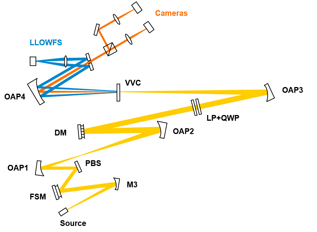
After a period of downselect, a vendor was identified with available master parabolic mirrors which would allow OAPs with focal lengths similar enough to the flight model and with the required surface quality and Talbot lengths to be produced. The specifications of the testbed OAPs are reported in Table 4 and their fractional Talbot lengths are reported in Table 5. To further decrease polarization and alignment error, the off-axis distances (OADs) of our OAPs were slightly reduced and modeled with vacuum-compatible mounts in SolidWorks at each design iteration to ensure the mounting hardware would not vignette the coronagraph beam.
| Optic | Radius of Curvature | Off-Axis Distance Change From Flight Model to Testbed |
| M3 | -293.6mm | 0mm |
| OAP1 | -254mm | 35mm |
| OAP2 | -346mm | 42mm |
| OAP3 | -914.4mm | 154mm |
| Distance (Optic 1 - Optic 2) | Value [mm] | / |
|---|---|---|
| M3-FSM | 145 | 0.16 |
| FSM-OAP1 | 126 | 0.14 |
| OAP1-OAP2 | 312 | 0.18 |
| OAP2-DM | 182 | 0.10 |
The final optical design of the prototype testbed can be seen in schematic in Figure 11 and as a 3D rendering in Figure 12.

5 Conclusions and Future Work
Here we have presented an overview of the proposed CDEEP missions and the science it will address. We have presented the design of the under-construction vacuum prototype testbed that will be used to accelerate software development and allow testing of a close to flight equivalent system in a space-like environment. We present simulations validating the ability of the proposed testbed design and wavefront sensing and control scheme to reach several requirements laid out in the overall CDEEP contrast budget, including contributions from polarization error, optical surface error, thermal deformation, jitter, and tolerance to alignment error.
Ongoing work includes selection of remaining components for the testbed, including the FSM and vacuum-compatible optics mounts, and some refinement of the optical layout to ensure optimum performance. Simulations are also being performed to compare the performance of the proposed design of CDEEP to a larger on-axis design. Future work will include further characterization of the processing requirements of EFC, as well as simulations of its performance when using realistic pairwise probing vs. perfect simulated knowledge of the image plane electric field.
Acknowledgements.
Many thanks to the coauthors of the CDEEP proposal for their hard work on said proposal in a very difficult time, and to those who gave feedback on this work. Portions of this work were supported by the Arizona Board of Regents Technology Research Initiative Fund (TRIF). Thanks also to Hop Bailey and the Arizona Space Institute for their support of the mission concept. An allocation of computer time from the UA Research Computing High Performance Computing (HPC) at the University of Arizona is gratefully acknowledged. Thanks to Zemax for the access to their OpticStudio STOP analysis feature. Special thanks to everyone at the Space Telescope Science Institute Russell B. Makidon Optics Laboratory for their advice.References
- [1] Winn, J. N. and Fabrycky, D. C., “The Occurrence and Architecture of Exoplanetary Systems,” Annu. Rev. Astro. 53(1), 409–447 (2015).
- [2] Wyatt, M. C., “Evolution of Debris Disks,” Annual Review of Astronomy and Astrophysics 46, 339–383 (Sept. 2008).
- [3] Krivov, A. V., “Debris disks: seeing dust, thinking of planetesimals and planets,” Research in Astronomy and Astrophysics 10, 383–414 (May 2010).
- [4] Matthews, B. C., Krivov, A. V., Wyatt, M. C., Bryden, G., and Eiroa, C., “Observations, Modeling and Theory of Debris Disks,” arXiv preprint arXiv:1401.0743 (2014).
- [5] Hughes, A. M., Duchene, G., and Matthews, B., “Debris Disks: Structure, Composition, and Variability,” arXiv:1802.04313 [astro-ph] (Feb. 2018). arXiv: 1802.04313.
- [6] Roberge, A., Chen, C. H., Millan-Gabet, R., Weinberger, A. J., Hinz, P. M., Stapelfeldt, K. R., Absil, O., Kuchner, M. J., and Bryden, G., “The Exozodiacal Dust Problem for Direct Observations of Exo-Earths,” PASP 124, 799–808 (Aug. 2012).
- [7] Kral, Q., Krivov, A. V., Defrère, D., Lieshout, R. v., Bonsor, A., Augereau, J.-C., Thébault, P., Ertel, S., Lebreton, J., and Absil, O., “Exozodiacal clouds: hot and warm dust around main sequence stars,” Astronomical Review 0, 1–43 (Sept. 2017).
- [8] Backman, D. E., “Exozodiacal Dust Workshop,” in [Exozodiacal Dust Workshop ], National Aeronautics and Space Administration, Ames Research Center ; Available from National Technical Information Service, Moffett Field, Calif.; Springfield, VA (1998).
- [9] Stark, C. C., Roberge, A., Mandell, A., and Robinson, T. D., “Maximizing the ExoEarth Candidate Yield from a Future Direct Imaging Mission,” ApJ 795(2), 122 (2014).
- [10] Turnbull, M. C., Glassman, T., Roberge, A., Cash, W., Noecker, C., Lo, A., Mason, B., Oakley, P., and Bally, J., “The Search for Habitable Worlds. 1. The Viability of a Starshade Mission,” PASP 124(915), 418 (2012).
- [11] Guyon, O., “Limits of Adaptive Optics for High-Contrast Imaging,” The Astrophysical Journal 629, 592–614 (Aug. 2005).
- [12] Males, J. R. and Guyon, O., “Ground-based adaptive optics coronagraphic performance under closed-loop predictive control,” JATIS, JATIAG 4, 019001 (Feb. 2018).
- [13] Ertel, S., Defrère, D., Hinz, P., Mennesson, B., Kennedy, G. M., Danchi, W. C., Gelino, C., Hill, J. M., Hoffmann, W. F., Mazoyer, J., Rieke, G., Shannon, A., Stapelfeldt, K., Spalding, E., Stone, J. M., Vaz, A., Weinberger, A. J., Willems, P., Absil, O., Arbo, P., Bailey, V. P., Beichman, C., Bryden, G., Downey, E. C., Durney, O., Esposito, S., Gaspar, A., Grenz, P., Haniff, C. A., Leisenring, J. M., Marion, L., McMahon, T. J., Millan-Gabet, R., Montoya, M., Morzinski, K. M., Perera, S., Pinna, E., Pott, J.-U., Power, J., Puglisi, A., Roberge, A., Serabyn, E., Skemer, A. J., Su, K. Y. L., Vaitheeswaran, V., and Wyatt, M. C., “The HOSTS Survey for Exozodiacal Dust: Observational Results from the Complete Survey,” AJ 159, 177 (Mar. 2020). Publisher: American Astronomical Society.
- [14] Kuchner, M. J. and Stark, C. C., “COLLISIONAL GROOMING MODELS OF THE KUIPER BELT DUST CLOUD,” The Astronomical Journal 140, 1007–1019 (Oct. 2010).
- [15] Allan, G., Douglas, E. S., Barnes, D., Egan, M., Furesz, G., Grunwald, W., Gubner, J., Haughwout, C., Holden, B. G., do Vale Pereira, P., and others, “The deformable mirror demonstration mission (DeMi) CubeSat: optomechanical design validation and laboratory calibration,” in [Proc. SPIE ], 10698, 1069857 (2018). tex.organization= International Society for Optics and Photonics.
- [16] Morgan, R. E., Douglas, E. S., Allan, G. W., Bierden, P., Chakrabarti, S., Cook, T., Egan, M., Furesz, G., Gubner, J. N., Groff, T. D., Haughwout, C. A., Holden, B. G., Mendillo, C. B., Ouellet, M., do Vale Pereira, P., Stein, A. J., Thibault, S., Wu, X., Xin, Y., and Cahoy, K. L., “MEMS Deformable Mirrors for Space-Based High-Contrast Imaging,” Micromachines 10, 366 (June 2019). Citation Key Alias: morgan_mems_2019-1.
- [17] Mendillo, C. B., Howe, G. A., Hewawasam, K., Martel, J., Finn, S. C., Cook, T. A., and Chakrabarti, S., “Optical tolerances for the PICTURE-C mission: error budget for electric field conjugation, beam walk, surface scatter, and polarization aberration,” in [Proc SPIE ], 10400, 1040010, International Society for Optics and Photonics (Sept. 2017).
- [18] Mendillo, C. B., Hicks, B. A., Cook, T. A., Bifano, T. G., Content, D. A., Lane, B. F., Levine, B. M., Rabin, D., Rao, S. R., Samuele, R., Schmidtlin, E., Shao, M., Wallace, J. K., and Chakrabarti, S., “PICTURE: a sounding rocket experiment for direct imaging of an extrasolar planetary environment,” in [Proc. SPIE ], 8442 (Sept. 2012).
- [19] Chakrabarti, S., Mendillo, C., and Cook, T. A., “Planet Imaging Coronagraphic Technology Using a Reconfigurable Experimental Base (PlCTURE-B): The Second in the series of Suborbital Exoplanet Experiments,” Journal of Astronomical Instrumentation Submitted(Submitted) (2015).
- [20] Douglas, E. S., Mendillo, C. B., Cook, T. A., Cahoy, K. L., and Chakrabarti, S., “Wavefront sensing in space: flight demonstration II of the PICTURE sounding rocket payload,” Journal of Astronomical Telescopes, Instruments, and Systems 4, 019003 (Jan. 2018).
- [21] Belikov, R., Lozi, J., Pluzhnik, E., Hix, T. T., Bendek, E., Thomas, S. J., Lynch, D. H., Mihara, R., Wes Irwin, J., Duncan, A. L., Greene, T. P., Guyon, O., Kendrick, R. L., Smith, E. H., Witteborn, F. C., and Schneider, G., “EXCEDE Technology Development III: First Vacuum Tests,” ArXiv e-prints 1407, 4393 (July 2014).
- [22] Sirbu, D., Thomas, S. J., Belikov, R., Lozi, J., Bendek, E., Pluzhnik, E., Lynch, D. H., Hix, T., Zell, P., Schneider, G., and Guyon, O., “EXCEDE technology development IV: demonstration of polychromatic contrast in vacuum at 1.2 L/D,” in [Techniques and Instrumentation for Detection of Exoplanets VII ], 9605, 96050J, International Society for Optics and Photonics (Sept. 2015).
- [23] Mawet, D., Serabyn, E., Liewer, K., Hanot, C., McEldowney, S., Shemo, D., and O’Brien, N., “Optical vectorial vortex coronagraphs using liquid crystal polymers: theory, manufacturing and laboratory demonstration,” arXiv preprint arXiv:0912.0311 (2009).
- [24] Mawet, D., Serabyn, E., Liewer, K., Burruss, R., Hickey, J., and Shemo, D., “The Vector Vortex Coronagraph: Laboratory Results and First Light at Palomar Observatory,” ApJ 709, 53 (Jan. 2010).
- [25] Ruane, G., Crill, B., Patterson, K., Prada, C. M., Seo, B.-J., and Siegler, N., “Decadal Survey Testbed Commissioning Roadmap: Demonstrating Technology for Imaging New Worlds,” Jet Propulsion Laboratory, NASA ExEP Program roadmap , 11 (2019).
- [26] Serabyn, G., Mawet, D., Ruane, G., Mejia-Prada, C., and Jovanovic, N., “TECHNOLOGY DEVELOPMENT FOR EXOPLANET MISSONS: Technology Milestone White Paper Vortex Coronagraph Technology,” TDEM White Paper, JPL TDEM Whitepaper (2019).
- [27] [Experimental analysis of the achromatic performance of a vector vortex coronagraph ], 11443(258) (2020).
- [28] Mawet, D., Pueyo, L., Moody, D., Krist, J., and Serabyn, E., “The Vector Vortex Coronagraph: sensitivity to central obscuration, low-order aberrations, chromaticism, and polarization,” in [Proc SPIE ], 773914 (July 2010).
- [29] Murakami, N., Hamaguchi, S., Sakamoto, M., Fukumoto, R., Ise, A., Oka, K., Baba, N., and Tamura, M., “Design and laboratory demonstration of an achromatic vector vortex coronagraph,” Opt. Express, OE 21, 7400–7410 (Mar. 2013).
- [30] N’Diaye, M., Choquet, E., Pueyo, L., Elliot, E., Perrin, M. D., Wallace, J. K., Groff, T., Carlotti, A., Mawet, D., Sheckells, M., and et al., “High-contrast imager for complex aperture telescopes (hicat): 1. testbed design,” Techniques and Instrumentation for Detection of Exoplanets VI (Sep 2013).
- [31] Goodman, J. W., “Introduction to fourier optics,” Introduction to Fourier optics, 3rd ed., by JW Goodman. Englewood, CO: Roberts & Co. Publishers, 2005 1 (2005).
- [32] Douglas, E. S. and Perrin, M. D., “Accelerated modeling of near and far-field diffraction for coronagraphic optical systems,” in [Proc SPIE ], MacEwen, H. A., Lystrup, M., Fazio, G. G., Batalha, N., Tong, E. C., and Siegler, N., eds., 100, SPIE, Austin, United States (July 2018).
- [33] Prada, C. M., Serabyn, E., and Shi, F., “High-contrast imaging stability using MEMS deformable mirror,” in [Techniques and Instrumentation for Detection of Exoplanets IX ], 11117, 1111709, International Society for Optics and Photonics (Sept. 2019).
- [34] Douglas, E. S., Hewasawam, K., Mendillo, C. B., Cahoy, K. L., Cook, T. A., Finn, S. C., Howe, G. A., Kuchner, M. J., Lewis, N. K., Marinan, A. D., Mawet, D., and Chakrabarti, S., “End-to-end simulation of high-contrast imaging systems: methods and results for the PICTURE mission family,” in [Proc. SPIE ], 9605, 96051A–96051A–13 (2015).
- [35] Stapelfeldt, K., Belikov, R., Bryden, G., Cahoy, K., Chakrabarti, S., Marley, M., McElwain, M., Meadows, V., Serabyn, E., Trauger, J., and others, “Exo-C imaging nearby worlds,” by the Science and Technology Definition Team (STDT) and the Exo-C Design team, final report, http://exep. jpl. nasa. gov/stdt/Exo-C_Final_Report_for_Unlimited_Release_150323. pdf (2015).
- [36] Gaudi, B. S., Seager, S., Mennesson, B., Kiessling, A., Warfield, K., Kuan, G., Cahoy, K., Clarke, J. T., Domagal-Goldman, S., Feinberg, L., Guyon, O., Kasdin, J., Mawet, D., Robinson, T., Rogers, L., Scowen, P., Somerville, R., Stapelfeldt, K., Stark, C., Stern, D., Turnbull, M., Martin, S., Alvarez-Salazar, O., Amini, R., Arnold, W., Balasubramanian, B., Baysinger, M., Blais, L., Brooks, T., Calvet, R., Cormarkovic, V., Cox, C., Danner, R., Davis, J., Dorsett, L., Effinger, M., Eng, R., Garcia, J., Gaskin, J., Harris, J., Howe, S., Knight, B., Krist, J., Levine, D., Li, M., Lisman, D., Mandic, M., Marchen, L., Marrese-Reading, C., McGowen, J., Miyaguchi, A., Morgan, R., Nemati, B., Nikzad, S., Nissen, J., Novicki, M., Perrine, T., Redding, D., Richards, M., Rud, M., Scharf, D., Serabyn, G., Shaklan, S., Smith, S., Stahl, M., Stahl, P., Tang, H., Van Buren, D., Villalvazo, J., Warwick, S., Webb, D., Wofford, R., Woo, J., Wood, M., Ziemer, J., Douglas, E., Faramaz, V., Hildebrandt, S., Meshkat, T., Plavchan, P., Ruane, G., and Turner, N., “The Habitable Exoplanet Observatory (HabEx) Mission Concept Study Interim Report,” ArXiv e-prints 1809, arXiv:1809.09674 (Sept. 2018).
- [37] Serabyn, E., “Technology Milestone White Paper Vortex Coronagraph Technology,” (Mar. 2016).
- [38] Por, E. H., Haffert, S. Y., Radhakrishnan, V. M., Doelman, D. S., Kooten, M. v., and Bos, S. P., “High Contrast Imaging for Python (HCIPy): an open-source adaptive optics and coronagraph simulator,” in [Adaptive Optics Systems VI ], 10703, 1070342, International Society for Optics and Photonics (July 2018).
- [39] Noll, R. J., “Zernike polynomials and atmospheric turbulence,” J. Opt. Soc. Am. 66, 207–211 (Mar. 1976).
- [40] Give’on, A., Shaklan, S., and Kern, B., “Electric field conjugation-based wavefront correction algorithm for high contrast imaging systems-experimental results,” in [In the spirit of Bernard Lyot: the direct detection of planets and circumstellar disks in the 21st century ], 1, 29 (2007).
- [41] Groff, T. D., Riggs, A. J. E., Kern, B., and Kasdin, N. J., “Methods and limitations of focal plane sensing, estimation, and control in high-contrast imaging,” JATIS 2, 011009 (Dec. 2015).
- [42] Trauger, J. T. and Traub, W. A., “A laboratory demonstration of the capability to image an Earth-like extrasolar planet,” Nature 446, 771–773 (Apr. 2007).
- [43] Jovanovic, N., Ruane, G., Echeverri, D., Delorme, J. R., Mawet, D., Fucik, J., Wallace, J. K., Coker, C., Delacroix, A., Levraud, N., Sayson, J. D. L., Wang, J., Riddle, R., and Millar-Blanchaer, M. A., “High-contrast spectroscopy testbed for Segmented Telescopes: instrument overview and development progress,” in [Ground-based and Airborne Instrumentation for Astronomy VII ], 10702, 107024E, International Society for Optics and Photonics (July 2018).
- [44] Llop-Sayson, J., Ruane, G., Mawet, D., Jovanovic, N., Coker, C. T., Delorme, J.-R., Echeverri, D., Fucik, J., Eldorado Riggs, A. J., and Wallace, J. K., “High-contrast Demonstration of an Apodized Vortex Coronagraph,” AJ 159, 79 (Feb. 2020).
- [45] Krist, J. E., “PROPER: an optical propagation library for IDL,” in [Proc. SPIE ], 6675, 66750P–66750P–9 (2007).
- [46] Guyon, O., Miller, K., Males, J., Belikov, R., and Kern, B., “Spectral Linear Dark Field Control: Stabilizing Deep Contrast for Exoplanet Imaging Using out-of-band Speckle Field,” arXiv:1706.07377 [astro-ph] (June 2017). arXiv: 1706.07377.
- [47] Belikov, R., Give’on, A., Kern, B., Cady, E., Carr, M., Shaklan, S., Balasubramanian, K., White, V., Echternach, P., Dickie, M., Trauger, J., Kuhnert, A., and Kasdin, N. J., “Demonstration of high contrast in 10% broadband light with the shaped pupil coronagraph,” in [Techniques and Instrumentation for Detection of Exoplanets III ], 6693, 66930Y, International Society for Optics and Photonics (Sept. 2007).
- [48] Bailey, V. P., Bottom, M., Cady, E., Cantalloube, F., Boer, J. d., Groff, T., Krist, J., Millar-Blanchaer, M. A., Vigan, A., Chilcote, J., Choquet, E., Rosa, R. J. D., Girard, J. H., Guyon, O., Kern, B., Lagrange, A.-M., Macintosh, B., Males, J. R., Marois, C., Meshkat, T., Milli, J., N’Diaye, M., Ngo, H., Nielsen, E. L., Rhodes, J., Ruane, G., Holstein, R. G. v., Wang, J. J., and Xuan, W., “Lessons for WFIRST CGI from ground-based high-contrast systems,” in [Space Telescopes and Instrumentation 2018: Optical, Infrared, and Millimeter Wave ], 10698, 106986P, International Society for Optics and Photonics (Aug. 2018).
- [49] Sun, H., Kasdin, N. J., and Vanderbei, R., “Efficient wavefront sensing for space-based adaptive optics,” JATIS 6, 019001 (Jan. 2020). Publisher: International Society for Optics and Photonics.
- [50] L., P., A., H. C., J., C. E., and L., C. K., “Computational requirements of image plane algorithms for high contrast imaging in space telescopes,” in prep. .
- [51] Mendillo, C. B., Howe, G. A., Hewawasam, K., Martel, J., Cook, T. A., and Chakrabarti, S., “Polarization aberration analysis for the PICTURE-C exoplanetary coronagraph,” JATIS 5, 025003 (May 2019).
- [52] Chipman, R. A., Lam, W.-S. T., and Young, G., [Polarized Light and Optical Systems ], CRC Press (2019).