CoMeT: An Integrated Interval Thermal Simulation Toolchain for 2D, 2.5D, and 3D Processor-Memory SystemsDOI: 10.1145Volume: 1113CCS: Hardware Dynamic memoryCCS: Hardware Temperature simulation and estimationCCS: Hardware Memory and dense storageCCS: Hardware Emerging architecturesCCS: Hardware Thermal issues
Abstract.
Processing cores and the accompanying main memory working in tandem enable the modern processors. Dissipating heat produced from computation remains a significant problem for processors. Therefore, the thermal management of processors continues to be an active subject of research. Most thermal management research is performed using simulations, given the challenges in measuring temperatures in real processors. Fast yet accurate interval thermal simulation toolchains remain the research tool of choice to study thermal management in processors at the system level. However, the existing toolchains focus on the thermal management of cores in the processors since they exhibit much higher power densities than memory.
The memory bandwidth limitations associated with 2D processors lead to high-density 2.5D and 3D packaging technology. 2.5D packaging technology places cores and memory on the same package. 3D packaging technology takes it further by stacking layers of memory on the top of cores themselves. These new packagings significantly increase the power density of the processors, making them prone to overheating. Therefore, mitigating thermal issues in high-density processors (packaged with stacked memory) becomes even more pressing. However, given the lack of thermal modeling for memories in existing interval thermal simulation toolchains, they are unsuitable for studying thermal management for high-density processors.
To address this issue, we present the first integrated Core and Memory interval Thermal simulation toolchain called CoMeT. CoMeT comprehensively supports thermal simulation of high- and low-density processors corresponding to four different core-memory (integration) configurations – off-chip DDR memory, off-chip 3D memory, 2.5D, and 3D. CoMeT supports several novel features that facilitate overlying system research. CoMeT adds only an additional 5% simulation-time overhead compared to an equivalent state-of-the-art core-only toolchain. The source code of CoMeT has been made open for public use under the MIT license.
Keywords:
3D memories, Thermal simulation, Stacked architectures
1. Introduction
Processing cores and the accompanying main memory working together make the modern processor work. It is common to fabricate the cores and memory separately on different packages using 2D packaging technology and then connect them using off-chip interconnects. However, the limited bandwidth of the interconnect often becomes the performance bottleneck in the 2D processor. Recent advances in semiconductor manufacturing have enabled high-density integration of core and memory wherein the designers place them on the same package using 2.5D packaging technology to improve bandwidth. Designers can now stack memory and core on top of each other as layers using 3D packing technology for several magnitudes increase in bandwidth (Loh et al. 2007). These advances enable the next generation of high-performing high-density 2.5D and 3D processors.
The tighter (and vertical) integration of core and memory into a single package results in the power of both core and memory getting channeled in the same package. However, there is not much increase in the package’s corresponding surface area. Consequently, the integration significantly increases the power density of the processor. Therefore, these high-density processors (packaged with stacked memory) face even more severe thermal issues than low-density 2D processors (Coudrain et al. 2016). Promising as they are, the thermal issues associated with high-density processors prevent them from going mainstream. Therefore, thermal management for high-density processors is now an active research subject (Hajkazemi et al. 2017; Lo et al. 2016; Siddhu and Panda 2019; Siddhu et al. 2020).
However, the availability of thermal sensors in real-processors is limited, and they often lack the temporal and spatial resolutions needed for thermal management research. Given the challenges involved in measuring temperatures in real-world processors, thermal simulations play an essential role in enabling thermal management research. However, due to the lack of better open-source tools, existing works on thermal management of high-density processors and most works on thermal management of low-density processors are based on in-house trace-based simulators (Cao et al. 2019). Recent advances in Electronic Design Automation (EDA) have enabled detailed core-only interval thermal simulations using sophisticated open-source toolchains (Pathania and Henkel 2018; Rohith et al. 2018; Hankin et al. 2021). Trace-based simulation relies on first collecting traces (performance, power) of each application running in isolation. It then performs segregated temperature simulations on the merged (independent) traces. In contrast, an interval-based simulation executes all applications in parallel, allowing it to consider contention on shared resources. The following motivational example shows that interval simulations are more detailed and accurate than trace-based simulations.
Motivational Example: Figure 1(a) shows a scenario in which two instances of SPLASH-2 ocean.ncont are executing in parallel. Both instances of ocean.ncont compete for DRAM bandwidth, which leads to a performance reduction of 16% due to stall cycles; trace-based simulation (I) cannot capture this effect. In addition, stall cycles reduce the power consumption and consequently the temperature. Therefore, trace-based simulation overestimates the temperature (II). One can overcome this overestimation by obtaining traces for all combinations of applications, but such an approach might already be prohibitive. Dynamic Voltage Frequency Scaling (DVFS) technology in processors further aggravates the problem. Scaling V/f levels affects the performance of memory- and compute-intensive applications differently. Figure 1(b) shows the traces of the compute-intensive PARSEC swaptions and the memory-intensive SPLASH-2 ocean.ncont at 4 GHz (top) and 1 GHz (bottom). The points in their execution the two applications reach (after 100 ms) at 4 GHz is different from the points they reach when operating at 1 GHz. Therefore, the trace one obtains at a constant of 1 GHz can not be used to continue a simulation that switches from 4 GHz to 1 GHz after 100 ms. The trace-based simulation would require traces of all combinations of applications at all V/f levels and all relative shifts of applications. The collection of all these traces is practically infeasible.
Cycle-accurate simulations (Binkert et al. 2011) are more accurate than interval simulations. However, they are also extremely slow and difficult to parallelize (often single-threaded). Cycle-accurate simulations are quintessential to test the accuracy of new micro-architecture designs, which designers can do in a limited number of processor cycles. In system research, on the other hand, we are required to simulate multiple (many) processors simultaneously for time measured in minutes (hours) rather than cycles to reproduce the necessary system-level behavior. For example, a single-core processor running at 1 GHz goes through a billion processor cycles every second. Cycle-accurate simulations are therefore too slow for system-level research. Interval simulations are several magnitudes faster than cycle-accurate simulations and provide a good trade-off between simulation speed and accuracy. Interval simulations are therefore best suited for system-level research that requires simulation of a multi-/many-core processor for a long duration but with high fidelity. However, existing interval thermal simulation toolchains do not model the main memory and cannot be used to study the high-density processors wherein core and memory are tightly integrated and thermally coupled.
In this work, we present the first interval thermal simulation toolchain, called CoMeT, that holistically integrates both core and memory. CoMeT provides performance, power, and temperature values at regular user-defined intervals (epochs) for core and memory. The support for thermal interval simulation for both core and memory using the CoMeT toolchain comes at only 5% additional simulation-time overhead over HotSniper (Pathania and Henkel 2018) (state-of-the-art thermal interval simulation toolchain for core-only simulations). CoMeT enables users to evaluate and analyze run-time thermal management policies for various core-memory (integration) configurations as shown in Figure 2 (Coudrain et al. 2016; Stow et al. 2016; Sodani 2015; Hassan et al. 2015; Park et al. 2021; Loh 2008). Figure 2(a) shows a conventional but the most common configuration with cores and 2D DRAM on separate packages. Figure 2(b) replaces the 2D DRAM with a 3D memory for faster data access. Figure 2(c) further bridges the gap between core and 3D memory by putting them side by side within a package. Figure 2(d) advances the integration by stacking cores over the 3D memory to reduce data access delays further. We refer to configurations shown in Figures 2(a), 2(b), 2(c), and 2(d) as 2D-ext, 3D-ext, 2.5D, and 3D-stacked, respectively.
We see CoMeT primarily as a tool for system-level thermal management research. CoMeT, therefore, comes equipped with several features that facilitate system research. CoMeT ships with SchedAPI Application Programming Interface (API) library, which the users can use to implement their custom thermal (resource) management policies. We also develop and integrate HeatView into CoMeT, which generates a representative video of the thermal simulation for a quick human-comprehensible visual analysis. It also contains an integrated floorplan generator. CoMeT has an extendable automatic build verification (smoke) test suite that checks critical functionalities across various core-memory configurations and their underlying architectural parameters for quick validation of code edits. We develop and integrate the SimulationControl framework in CoMeT, using which the users can run simulations for various workloads and configurations in batch mode.
Using CoMeT, we also illustrate the thermal patterns for different core-memory configurations using benchmarks from several diverse benchmark suites. These experiments helped us develop many insights into the thermal interactions of cores and memory and their influence on each other’s temperatures. We also present a thermal-aware scheduling case study wherein we simulate operations of the default on-demand Governor (Pallipadi and Starikovskiy 2006) from Linux operating in conjunction with a Dynamic Thermal Management (DTM) on a 3D stacked processor. We make several new interesting thermal observations through our case study. In the same spirit, we envision other researchers will also identify several new thermal behaviors for existing and upcoming core-memory configurations using CoMeT. Consequently, CoMeT will enable them to propose and evaluate novel thermal management policies for these configurations.
In particular, we make the following key contributions in this work.
- (1)
We introduce an open-source interval thermal simulation toolchain, called CoMeT, that holistically integrates core and memory. It supports the simulation of multi-/many-core processors in several different core-memory configurations.
- (2)
We describe several novel features in CoMeT that facilitate system-level thermal management research in processors.
- (3)
We perform thermal analysis of different core-memory configurations using CoMeT and present new interesting thermal observations. We also highlight the suitability of CoMeT for studying thermal-aware system scheduling via a case study.
Open Source Contribution: The source code for CoMeT is released under MIT license for unrestricted use and is available for download at https://github.com/marg-tools/CoMeT.
2. Background and Related Work
Thermal-aware design of computing systems has been a significant area of research since the early 2000s. With the current technology nodes, the phenomenon of dark silicon (not being able to use the entire chip simultaneously due to thermal issues) (Pathania and Henkel 2018; Henkel et al. 2015) is becoming prominent. It is driving the need for fine-grained thermal management to respect the thermal limits of the system. Multi-/many-core processors exhibit unbalanced temperatures and distributed thermal hotspots, making thermal management non-trivial (Khdr et al. 2014). Various works have addressed thermal management for cores using different techniques (Huang et al. 2000; Lasbouygues et al. 2007; Calimera et al. 2008; Bao et al. 2009; Homayoun et al. 2010; Kumar and Atienza 2010; Bailis et al. 2011; Ayoub et al. 2013; Liu et al. 2013; Cox et al. 2013; Sironi et al. 2013; Zapater et al. 2013; Cochran and Reda 2013; Sridhar et al. 2013; Juan et al. 2014; Khdr et al. 2014; Zhang et al. 2015; Prakash et al. 2016; Bogdan et al. 2016; Zheng et al. 2016; Wang et al. 2017; Kumar et al. 2017; Liu et al. 2018; Pathania and Henkel 2018; Yang et al. 2018; Sadrosadati et al. 2019; Rapp et al. 2021). These works primarily include voltage and frequency scaling, hardware reconfiguration, power and clock gating, and cache throttling as knobs for thermal management. They propose proactive thermal management policies such as task allocation based on future temperature and reactive thermal management policies such as task migration and scheduling for cores. Also, some works have addressed optimizing multiple metrics such as energy, power, and temperature. To name a few, Huang et al. (Huang et al. 2000) proposed a framework for dynamic management of energy and temperature of core in a unified manner. Khdr et al. (Khdr et al. 2014) proposed a technique that employs centralized and distributed predictors to prevent violating temperature thresholds while maintaining the balance between the temperature of different cores. Zapater et al. (Zapater et al. 2013) proposed a temperature- and leakage-aware control policy to reduce the energy consumption of data centers by controlling the fan speed.
Designing appropriate thermal management policies requires a fast and accurate thermal simulator for quick evaluation, which has resulted in the development of various open-source thermal simulators such as 3D-ICE (Sridhar et al. 2013) and HotSpot (Zhang et al. 2015). Such thermal simulators (Zhang et al. 2015; Sridhar et al. 2013; Li et al. 2020; Sultan and Sarangi 2020; Sultan and Sarangi 2021; Wang et al. 2017) use floorplan and power traces as inputs and generate temperature values as output. 3D-ICE (Sridhar et al. 2013) is a thermal simulator having a transient thermal model with microchannel cooling for liquid-cooled ICs. HotSpot (Zhang et al. 2015) provides a fast and accurate thermal model for transient and steady-state simulations. Thermal simulators pave the way for an early-stage understanding of potential thermal issues in chips and facilitate studies to understand the implications of different designs and floorplans and develop cooling solutions. A performance simulator for processors, such as Sniper (Carlson et al. 2014) or gem5 (Binkert et al. 2011), integrated with a power model (such as McPAT (Li et al. 2009)) generates the power traces used inside these thermal simulators. McPAT (Li et al. 2009) framework can model the power, area, and timing of processor components. It supports technology nodes ranging from 90 nm to 22 nm. Sniper (Carlson et al. 2014) is a multi-/many-core performance simulator that uses interval simulation to simulate a system at a higher level of abstraction than a detailed cycle-accurate simulator. Sniper achieves several magnitudes faster simulation speeds over a cycle-accurate simulator such as gem5. Sniper integrates McPAT and enables regular monitoring of the processor’s power consumption.
Looking at the memory part, DRAMsim3 (Li et al. 2020) and HMCTherm (Yang et al. 2018) are cycle-accurate DRAM simulators and support thermal simulation. While DRAMsim3 models 2D and 3D DRAMs, HMCTherm models 3D memory based on Hybrid Memory Cube (HMC) specification. The detailed cycle-accurate modeling significantly reduces their simulation speed and makes them unsuitable for integration with existing core-only interval-based performance simulators (Carlson et al. 2014). Further, DRAMsim3 and HMCTherm focus on off-chip memories and do not consider novel technologies such as 2.5D or 3D integration of cores and memories. CACTI-3DD (Chen et al. 2012) is an architecture-level integrated power, area, and timing modeling framework for new memory technologies such as 3D-stacked memories in addition to commodity 2D DRAM and caches. It enables easier integration with an architectural-level core performance simulator.
Several works have used trace-based evaluation for core thermal management policies (Cox et al. 2013; Zheng et al. 2016; Liu et al. 2018; Deshwal et al. 2019). Cox et al. (Cox et al. 2013) use trace-based simulation using HotSpot to obtain temperature and perform a thermal-aware mapping of streaming applications on 3D processors. Liu et al. (Liu et al. 2018) use a trace-based thermal simulation methodology using power traces generated from gem5 + McPAT for dynamic task mapping on systems with reconfigurable network-on-chip. A thermal-aware design space exploration work, MOOS (Deshwal et al. 2019), generates power traces from gem5 and McPAT and uses HotSpot and a custom analytical model for temperature estimation of 3D integrated cores and caches. Such a trace-based approach was sufficient for their work as they did not consider any dynamic policy for thermal management. A key limitation of evaluating thermal management policies using trace-based simulations is that they do not feed the temperature impact into the performance simulator. This limitation limits the accuracy and scope of the analysis. Many aspects of thermal management, such as reducing the frequency of heated cores based on temperature or adapting cache partitioning based on temperature, cannot be captured by traces collected in isolation and hence can lead to errors or inaccuracies in the overall evaluation. Further, as motivated in Section 1, an infeasible number of traces might need to be generated to capture the parameter tuning in both performance and thermal simulators.
Addressing these issues associated with trace-based simulators requires integrating performance and thermal simulators in a coherent manner. HotSniper was the first to provide an integrated infrastructure for interval-based performance and thermal simulation of 2D processor cores. HotSniper (Pathania and Henkel 2018) integrates the Sniper performance simulator with HotSpot thermal simulator and provides an infrastructure for core-only interval thermal simulations of multi-/many-core processors. HotSniper enables a feedback path for temperature from the thermal simulator (HotSpot) to the performance simulator (Sniper) to help make thermal-aware decisions for thermal management. LifeSim (Rohith et al. 2018) is another notable example of a similar attempt with an additional focus on thermals-based reliability. Recently released HotGauge (Hankin et al. 2021) integrates Sniper with 3D-ICE.
Conventionally, memories have lower power dissipation and thus induce lower heating (compared to high-frequency cores (Bircher and John 2008)), thereby requiring limited thermal management. Therefore, prior works such as HotSniper supported thermal analysis only for cores. With increasing memory bandwidth requirements of applications, high-density 3D-ext, 2.5D, and 3D-stacked processors are becoming popular but face severe thermal issues (Hajkazemi et al. 2017; Lo et al. 2016). Furthermore, high-density processors (and memories within) have significant leakage power dissipation that increases with temperature and forms a positive feedback loop between leakage power and temperature. Therefore, in recent times, memory heating in high-density processors has also received significant research attention (Siddhu et al. 2020; Siddhu and Panda 2019). FastCool (Siddhu et al. 2020) discusses DTM strategies for 3D memory considering the leakage power dissipation in memory and positive feedback loop between leakage power and temperature. PredictNCool (Siddhu and Panda 2019) proposes a proactive DTM policy for 3D memories using a lightweight steady-state temperature predictor. Instead of using detailed command level 3D memory models (Li et al. 2020; Yang et al. 2018), both FastCool and PredictNCool obtain energy-per-access from CACTI-3DD (Chen et al. 2012) to derive memory power based on access traces and used HotSpot for thermal simulation in a trace-based methodology. While they use the same tools (CACTI-3DD, Sniper, and HotSpot) used in CoMeT, their evaluation suffers from the already discussed limitations of a trace-based simulation. Moreover, such a setup cannot provide dynamic feedback to cores, limiting its scope and accuracy.
3. COMET: Integrated Thermal Simulation for Cores and Memories
CoMeT integrates a performance simulator (Sniper (Carlson et al. 2014)), a power model for core (McPAT (Li et al. 2009)), a power model for memory (CACTI (Chen et al. 2012)), and a thermal simulator (HotSpot (Zhang et al. 2015)) to perform an integrated interval performance, power, and thermal simulation for cores and memories. It also provides many other useful features and utilities to handle multiple core-memory configurations, thermal management, floorplan generation, etc., within the framework. We present the proposed CoMeT tool flow and features in this section.
3.1. CoMeT Tool Flow
We first provide an overview of the CoMeT toolchain and then explain each block in detail.
3.1.1. Overview
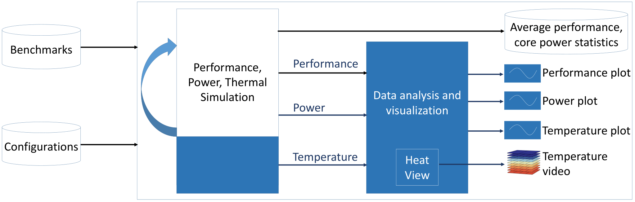
Figure 3 shows an overall picture of the CoMeT toolchain. Components in blue indicate the key contributions of CoMeT. The toolchain first invokes an interval performance simulator (e.g., Sniper (Carlson et al. 2014)) to simulate a workload and tracks access counts to various internal components such as execution units, caches, register files, etc. We also extended the existing performance simulator to monitor memory access counts. The access counts are accumulated and passed to the power model at every epoch (e.g., ). The power model (e.g., McPAT (Li et al. 2009)) calculates the core and memory power during the corresponding epoch, which toolchain then feeds along with the chip floorplan to a thermal simulator (e.g., HotSpot (Zhang et al. 2015)) for calculating core and memory temperature. Depending upon the type of core-memory configuration, thermal simulation of core and memory can occur separately (Figures 2(a), (b)) using two different invocations of the thermal simulator or together (Figures 2(c), (d)) using a single invocation. As shown in Figure 3, the toolchain provides the core and memory temperatures as inputs to the DTM policy. If the temperature exceeds a threshold, the DTM policy will invoke knobs (e.g., changing the core and memory power state, operating voltage/frequency, task/data mapping, etc.) to manage the temperature. Such knobs would affect the performance simulation, and the above process repeats until the end of the workload. Once the simulation is complete, CoMeT collects various metrics such as IPC, cache hit rate, DRAM bandwidth utilization, etc., from the performance simulator, power traces from the power model, and temperature traces from the temperature simulator. These metrics and traces are processed to generate different plots and statistics, enabling easier and more detailed analysis. We provide details of each of these blocks in the following subsection.
3.1.2. Toolchain Details
Figure 4 shows different blocks of the CoMeT flow in more detail. Figure 4(a) illustrates the performance simulation block, which simulates a workload and provides access counts of different core blocks and memory. We updated the Sniper (Carlson et al. 2014) performance simulator to monitor and accumulate memory read (RD) access and write (WR) access counts (separately for each bank) in each epoch. Modern-day cores use various voltage-frequency levels and scheduling strategies to improve performance, increase energy efficiency, and reduce temperature. We provide an ondemand governor and a scheduler for open systems (Feitelson and Rudolph 1998) as default policies that users can suitably modify (more details in Section 3.5) to jumpstart development. The DVFS controller and the scheduler control various aspects of performance simulation and form inputs to the performance simulator. The user defines different processor architecture parameters such as the number of cores, frequency range, cache sizes, etc., as a part of settings. CoMeT then provides the settings as inputs to the performance simulation block.
We move now to explain the power model block shown in Figure 4. CoMeT uses the access counts generated from the performance simulation block, the power state, and operating voltage/frequency of each core to calculate core and memory power at every epoch. The core and memory power is calculated separately for each core and bank, respectively. The settings provide various technology parameters (e.g., technology node in nano-meters) and architecture parameters (such as cache attributes, number of functional units, etc.) as inputs to the power model. CoMeT calculates the core power using McPAT (Li et al. 2009). CoMeT first extracts the energy per access for RD and WR operation from a memory modeling tool (CACTI-3DD (Chen et al. 2012)) to calculate the memory power. This energy per access data is used within the access rate to the power converter block to convert the RD and WR access counts of each bank to corresponding dynamic power.
The next block is the thermal simulation block (Figure 4(c)), which calculates the temperature of individual core and memory banks using their power consumption and the chip floorplan/layer information. While a user can provide a floorplan file developed manually, we also implemented an automatic floorplan generator to generate the floorplan for various regular layouts (details in Section 3.7)). The users provide the floorplan as an input to the thermal simulation block. We use a fast and popular thermal simulator called HotSpot (Zhang et al. 2015)11 1 CoMeT uses HotSpot as the thermal simulator, but one can extend it to support any other (more accurate) thermal simulator. This extension is possible because most thermal simulators (e.g., HotSpot, 3D-ICE) follow similar input-output interfaces but different formats. During each interval, these simulators require a power trace as an input (generated by a performance simulator like Sniper) and generate temperature trace as an output. Therefore, an addition of a trace format converter within CoMeT should suffice to support different thermal simulators. These simulators also require configuration parameters and floorplan information as inputs which typically remain unchanged during the entire simulation. Thus, different thermal simulators can be supported by generating this information in an appropriate format, either manually or through automation (e.g., floorplanlib). A plugin-type integration of various simulators would be useful, and we leave it as future work for now., within CoMeT, extended to combine the dynamic power with the temperature-dependent leakage power at each epoch. Section 3.3 presents details of the temperature-dependent leakage-aware modeling. The user provides the thermal and tool parameters (epoch time, initial temperatures, config file, etc.) to the thermal simulation block.
As shown in Figure 4(d), the DTM policy manages temperature by employing a range of actions, such as using low power states, decreasing core voltage-frequency (V/F), changing the task/data mapping, and reducing power density. We provide a default throttle-based scheme (Section 3.5), which can be used as a template to help users develop and evaluate different thermal management schemes. The DTM policy uses the temperature data provided by the thermal simulation block and controls the power states, V/F settings, or the task/data mapping. The performance simulation and power model block make use of these knobs.
After the workload simulation completes, using SimulationControl, CoMeT outputs the performance, power, and temperature for various timesteps for both core and memory (not shown in Figure 4). Such traces are also available in graphical format, enabling a quicker and better analysis. In addition, HeatView generates a temperature video showing the thermal map of various cores and memory banks at different time instances. SimulationControl allows users to run simulations in batch mode (Section 3.4) on the input side. We elaborate on the various key features of CoMeT in the following subsections.
3.2. Support for Multiple Core-Memory Configurations
In this section, we discuss various core-memory configurations supported in CoMeT. Today’s technology supports integrating the core and memory in a processor (computer system) in multiple ways (Hassan et al. 2015). As shown in Figure 2, we support four different kinds of core-memory configurations in CoMeT. Designers can package the core and memory separately (Figure 2(a), (b)) or on the same package (Figure 2(c), (d)). They also solder the packaged chips onto a Printed Circuit Board (PCB) for mechanical stability and electrical connectivity.
Off-chip 2D core-memory configurations (Jacob 2009), referred to as 2D-ext in this work, are the most widely used configurations today. In such core-memory configurations, usually, the core has a heat sink for cooling while the DRAM memory is air-cooled (Figure 2(a)). The CoMeT toolchain studies thermal issues in such core-memory configurations. In many processors, off-chip 3D memories are becoming popular with the rising need for higher memory bandwidth. However, the increased power density causes thermal issues, requiring a heat sink for memory cooling (Figure 2(b)). We refer to such core-memory configurations as 3D-ext in this work. The 3D memory contains a logic core layer (not shown in the figure) at the bottom which manages the routing of requests and data between various layers of the 3D memory.
The above off-package core-memory configurations (2D-ext or 3D-ext) have a higher interconnect delay. In an alternative core-memory configuration referred to as 2.5D (Coudrain et al. 2016; Hassan et al. 2015) (Figure 2(c)), a 3D memory and 2D core are placed within the same package, thereby reducing the interconnect delay. An interposer (Coudrain et al. 2016) acts as a substrate and helps route connections between the memory and core. However, the thermal behavior gets complicated as the design places memory and core closer, influencing each other’s temperature. In Figure 2(d), the core and memory are stacked, achieving the lowest interconnect delay. Designers prefer to place the core nearer to the heat sink for better cooling. We refer to such a core-memory configuration as 3D-stacked in this work. CoMeT supports all these four core-memory configurations with various options to configure the number of cores, memory banks, and layers. CoMeT also models the power dissipation from the logic core layer in the 3D-ext and 2.5D configurations. We perform a detailed analysis of thermal patterns for these four core-memory configurations and present the corresponding observations in Section 4. We built CoMeT to consider certain aspects of various recent emerging memory technologies where a Non-Volatile Memory (NVM) (Salkhordeh and Asadi 2016), such as Phase Change Memory (PCM), acts as the main memory. Unlike conventional DRAMs, the energy consumption for the read and write operations in PCM is considerably different. Hence, CoMeT needs to account reads and writes separately. CoMeT allows the user to specify separate parameters for the read and write energy per access, thereby providing hooks for being extended to support such emerging memory technologies. However, one limitation in replacing DRAM with NVM within CoMeT is the underlying architectural simulator (Sniper), which does not accurately model heterogeneous read and write access times for memory. We plan to work in the future to overcome this limitation.
3.3. Leakage-Aware Thermal Simulation for Memories
As the temperature rises, the leakage power consumption increases. This increase raises the temperature, forming a temperature-leakage positive feedback loop. We model the thermal effects of temperature-dependent leakage power (for memories) similar to (Siddhu and Panda 2019) and validate them using ANSYS Icepak (Icepak 2021), a commercial detailed temperature simulator. We use CACTI-3DD (Chen et al. 2012) to note variations in the leakage power dissipation of the memory bank with temperature. We observe that, for memories, the leakage power contributes significantly (40%) to the total power dissipation (at 70°C, see Figure 5). In CoMeT, we obtain (using exponential curve fitting) and add the temperature-dependent leakage power consumption during thermal simulation. Following a similar approach, we use McPAT to extend HotSpot to account for temperature-dependent leakage power for cores.
3.4. Simulation Control Options
A common use-case with multi-/many-core simulators is to run many simulations that vary only in a few parameters, such as the workload and architectural parameters. These simulation runs are then quantitatively compared. CoMeT’s SimulationControl package provides features to facilitate this use case (Figure 6). It enables running simulations in batch mode and stores the traces in separate folders. The SimulationControl package provides a simple Python API to specify the parameters of each simulation run: workload and CoMeT configuration options. After each run, CoMeT stores the generated traces in a separate folder and creates plots (images) for the major metrics (power, temperature, CPU frequency, IPS, CPI stacks, etc.). Optionally, it also automatically creates the thermal video using the HeatView feature (Section 3.6).
In addition to an API to run many different simulations, the SimulationControl package provides a Python API to read the generated traces and higher-level metrics (e.g., average response time, peak temperature, and energy). This API enables to build custom evaluation scripts. The SimulationControl package, for example, can run the same random workload at varying task arrival rates with different thermal management policies. It generates graphs that enable users to check the resulting temperature traces visually. Users can further perform evaluations using the SimulationControl API (e.g., print a table with the peak temperature of each run).
3.5. SchedAPI: Resource Management Policies for Application Scheduling, Mapping, and DVFS
Run-time thermal management affects the performance, power, and temperature of a multi-/many-core processor (Rapp et al. 2021). Conversely, the design of run-time thermal management techniques depends on the objective (e.g., performance or energy), the constraints (e.g., temperature), and also on the targeted platform and its characteristics (e.g., micro-architecture or cooling system). Thus, in research exists several thermal management techniques catering to different scenarios. The purpose of CoMeT is to facilitate the development and evaluation of novel run-time thermal management techniques targeting, but not limited to, the new (stacked) core-memory configurations. Thermal management utilizes knobs like application scheduling, mapping and migration, and Dynamic Voltage and Frequency Scaling (DVFS). It then makes decisions on these knobs using observations of the system state: applications and their characteristics, power consumption, core/memory temperature, etc. One needs to tightly integrate all these properties into the infrastructure to provide these metrics to a thermal management policy during the simulation.
Thermal management generally targets an open system, where applications arrive at times that are unknown beforehand (Feitelson and Rudolph 1998). HotSniper (Pathania and Henkel 2018) was the first toolchain to explore the concept of scheduling for open systems using Sniper. The scheduler API (schedAPI) in CoMeT extends this feature but with a strong focus on user-friendliness to integrate new policies for mapping, migration, and DVFS. The arrival times of the applications are configurable in several ways. CoMeT supports uniform arrival times, random arrival times (Poisson distribution), or explicit user-defined arrival times. Task mapping and migration follow the one-thread-per-core model, common in many-core processors (Boyd-Wickizer et al. 2008). The default policy assigns cores to an incoming application based on a static priority list. It is straightforward to extend the default policy to implement more sophisticated policies. DVFS uses freely-configurable voltage/frequency (V/f) levels. CoMeT comes with two reference policies: a policy that assigns static frequency levels (intended to characterize the system with different applications at different V/f levels) and the Linux ondemand governor (Pallipadi and Starikovskiy 2006). Users can configure the epoch durations (default to ) for scheduling, migration, and DVFS. A common use-case of CoMeT is the implementation and study of custom resource management policies. To this end, schedAPI provides APIs as abstract C++ classes that users can extend with custom policies, with minimal changes in the codebase. We discuss a case study of using such a policy in CoMeT and corresponding insights for a stacked architecture in Section 4.6.
3.6. HeatView
A workload executing on a typical multi-/many-core processor undergoes multiple heating and cooling phases. Such phases might occur due to the workload characteristics themselves or the effect of a DTM policy. In such cases, developing deeper insights into the workload behavior and operation of DTM policy is essential. However, analyzing various log files can be cumbersome and error-prone. We develop and integrate HeatView within CoMeT to analyze such thermal behavior. HeatView generates a video to visually present the simulation’s thermal behavior, with the temperature indicated through a color map. HeatView takes the temperature trace file generated from CoMeT as input and other configurable options and generates images corresponding to each epoch and a video of the entire simulation. The users can use the videos corresponding to different workloads (or core-memory configurations) for comparing heating patterns across workloads (or architectures).
HeatView configures according to the core-memory configurations to generate patterns. Depending upon the specified core-memory configuration type among the four choices (2D-ext, 3D-ext, 2.5D, or 3D-stacked), HeatView can represent a core and memory stacked over each other or side-by-side. The temperature scale used within HeatView to show the thermal patterns is also configurable. Additionally, to reduce the video generation time, HeatView provides an option to periodically skip frames based on a user-specified sampling rate.
HeatView also allows configuring of parameters to improve viewability. We present a 3D view of the core and memory (stacked or side-by-side) to the user by default. Users can specify the core or memory layer number to plot separately as a 2D map (Figures 8, 9, and 10). Figure 11 shows users can also view each layer separately. HeatView always plots the 2D-ext architecture as a 2D view (example in Figure 7).
3.7. Floorplan Generator
Thermal simulation of a 2D processor requires a floorplan that specifies the sizes and locations of various components (cores, caches, etc.) on the silicon die. It requires one floorplan per layer, and a layer configuration file specifies the layer ordering and thermal properties for a stacked processor. CoMeT comes with some built-in floorplans and layer configuration files for several different architectures and configurations, as examples.
However, in the general case of custom simulations, it is required to create floorplans and layer configuration files according to the properties of the simulated system. CoMeT comes with an optional helper tool (floorplanlib) to generate custom floorplans. The tool supports all the four core-memory configurations described in Figure 2. It supports creating regular grid-based floorplans, where cores and memory banks align in a rectangular grid. The user only needs to specify the number and dimensions of cores, memory banks, thicknesses of core or memory layers, the distance between core and memory (for 2.5D configurations), etc. In addition, it is possible to provide a per-core floorplan (e.g., ALU, register file, etc.), which replicates for each core in the generated floorplan. User can still provide more complex (irregular) floorplans manually to CoMeT.
3.8. Automated Build Verification (Smoke Testing)
While making changes to the code base, one might inadvertently introduce errors in an already working feature in the tool. To efficiently detect such scenarios, we provide an automated test suite with CoMeT for verifying the entire toolchain for the correct working of its key features. We use a combination of different micro-benchmarks to develop a test suite that tests various tool features. After the test completes, we summarize the pass/failure status of test cases and error logs to help users debug the causes of failure of CoMeT’s features. While the test-suite performs a comprehensive smoke test of all CoMeT features, users can control and limit the testing to only a subset of features to save time. The automated build verification tests further help users test critical functionalities of CoMeT when they plan to extend the toolchain by adding new test cases corresponding to the added functionalities. In addition to this, it would also facilitate debugging new thermal management policies quickly.
4. Experimental Studies
In this section, we discuss various experiments to demonstrate the features of CoMeT and discuss various insights developed through these studies. Further, we also quantify the simulation time overhead of CoMeT over the state-of-the-art.
4.1. Experimental Setup
We use a diverse set of benchmark suites – PARSEC 2.1 (Bienia et al. 2008), SPLASH-2 (Woo et al. 1995), and SPEC CPU2017 (Bucek et al. 2018) – to study the performance, power, and thermal profiles for core and memory. Table 2 lists the selected benchmarks from each suite. We classify the benchmarks into compute-intensive (blackscholes, swaptions, barnes, radiosity, lu.cont, raytrace, gcc, exchange, x264, nab, mcf), mixed (streamcluster, vips, dedup, bodytrack, water.nsq, cholesky), and memory-intensive (lbm, mcf) based on their memory access rate. We compile the source code for PARSEC 2.1 (with input size simmedium) and SPLASH2 benchmarks (with input size small) to get the binaries for simulation. We directly use pre-generated traces (Pinballs) from (Wu et al. 2018) for simulation (with 100M instructions) for SPEC CPU2017 benchmarks.
Table 1 shows the core and memory parameters for various core-memory configurations that we use in our experiments. We use CoMeT’s automated floorplanlib tool to generate the floorplans for various core-memory configurations. We run simulations using CoMeT and obtain performance, power, and temperature metrics for various workloads. HotSpot uses grid-level simulation with an 8x8 grid in the center mode. Thermal simulation is invoked periodically at frequency.
| Core Parameter | Value |
|---|---|
| Number of Cores | 4 |
| Core Model | 3.6 GHz, 1.2 V, 22 nm, out-of-order, 3 way decode, 84 entry ROB, 32 entry LSQ |
| L1 I/D Cache | 4/16 KB, 2/8-way, 64B-block |
| L2 Cache | Private, 64 KB, 8-way/64B-block |
| Memory Parameter | Value |
| 3D Memory (3D-ext, 2.5D, 3D-stacked) Configuration | 1 GB, 8 layer, 16 channels, 8 ranks, 1 bank per rank, closed page policy, 29/20/15 ns (latency), 7.6 GBps (per channel bandwidth) |
| 2D Memory Off-chip Configuration | 2 GB, 1 layer, 1 channel, 4 ranks, 4 bank per rank, closed page policy, 45 ns (latency), 7.6 GBps (per channel bandwidth) |
| Benchmark Suite | Selected Benchmarks |
|---|---|
| PARSEC 2.1 | dedup, streamcluster, vips, bodytrack, swaptions, blackscholes |
| SPLASH-2 | lu.cont, water.nsq, radiosity, raytrace, barnes, cholesky |
| SPEC CPU2017 | lbm, mcf, gcc, nab, x264, exchange |
4.2. Thermal Profile for Various Architecture Configurations
We present the thermal behavior of cores and memories for each of the four core-memory configurations supported by CoMeT. We consider exchange, x264, mcf, and lbm benchmarks from the SPEC CPU2017 suite and map them on Cores 0, 1, 2, and 3, respectively, to exercise a heterogeneous workload containing benchmarks of different memory intensity. Each core maps to a fixed set of 3D memory channels. Core 0 maps to Channels {0, 1, 4, 5}, Core 1 maps to Channels {2, 3, 6, 7}, Core 2 maps to Channels {8, 9, 12, 13}, and Core 3 maps to Channels {10, 11, 14, 15}. HeatView uses the temperature trace generated during the simulation to create a video of the thermal pattern of various cores and memory banks. The videos for the simulations are available online at tinyurl.com/cometVideos. Figures 7, 8, 9, and 10 present snapshots at of simulation time for each of the four architectures.
Figure 7 presents the temperature profile of cores and the external DDR memory. We observe that Cores 0 and 1 have relatively higher temperatures than Cores 2 and 3 due to the execution of compute-intensive benchmarks on Cores 0 and 1. Further, Core 1 has a slightly higher temperature than Core 0 as x264 is more compute-intensive than exchange. We do not observe any temperature gradient on the memory side. We consider a single channel for the 2D memory with accesses from different cores shared and uniformly distributed among banks, thereby eliminating any gradient. Figure 8 shows the temperature profile of cores and an external 8-layer 3D memory. As cores and memory banks physically locate on different chips, they do not influence each other’s temperature and have different thermal profiles. We see that the memory banks attain significantly higher temperatures. Further, due to the heat sink at the top of the 3D memory, the temperature of the lower layers is higher than that of the upper layers, with a gradual decrease as we move up the memory stack. Due to the heterogeneous nature of benchmarks and each core mapping to a fixed set of channels, we observe that different 3D memory channels attain different temperatures. In the cross-section view of a memory layer shown in the figure, Channels 10, 11, 14, and 15 correspond to lbm, a highly memory-intensive benchmark. lbm is a highly memory-intensive benchmark that results in high temperatures in the memory layer. Channels 0, 1, 4, and 5 are relatively cooler as they correspond to Core 0, which executes a compute-intensive benchmark (exchange). Channels 2, 3, 6, and 7 also correspond to a compute-intensive benchmark (x264), but Channels 6 and 7 have higher temperatures than Channels 2 and 3 due to thermal coupling from adjacent hot Channels 10 and 11. Different cores also attain different temperatures due to the differing nature of the benchmarks executed. While this core-memory configuration (3D-ext) differs from 2D-ext only in terms of using an external 3D memory compared to a DDR memory, we observe that the cores in 3D-ext (Figure 8) are relatively hotter than the cores in the 2D-ext (Figure 7) because of faster execution enabled by the 3D memory. CoMeT enables such insights due to the integrated core-memory thermal simulation that cannot be easily quantified (accurately) when using a standalone trace-based simulation infrastructure.


Figure 9 shows the temperature profile of cores and 3D memory integrated on the same package in a 2.5D configuration. Similar to the previous case of 3D-ext (Figure 8), we observe that different cores and different memory channels in the 2.5D core-memory configuration attain different temperatures due to the heterogeneous nature of the workload. Also, the core and memory are thermally coupled in the 2.5D core-memory configuration, resulting in significantly higher temperatures for the same workload. Since the cores are away from the heat sink compared to 3D-ext, their heat dissipation capability reduces, leading to much higher temperatures.
Figure 10 shows the thermal profile for a 3D-stacked configuration with one layer of four cores stacked over an 8-layer 3D memory. We observe that any layer of the memory is hotter than the corresponding layer in the 3D-ext or 2.5D core-memory configuration due to the increased stacking of cores on top of the 3D memory, limiting the heat dissipation paths further raising the temperature. Similar to other core-memory configurations, we observe that different memory channels attain different temperatures due to the heterogeneous nature of the workload. However, the cores heat almost uniformly given their proximity to the heat sink and their coupling with the memory layers. While Cores 0 and 1 executing compute-intensive benchmarks should attain higher temperatures than Cores 2 and 3, their corresponding memory channels exhibit lower temperatures due to fewer memory accesses and help absorb the excess heat. CoMeT enables such insights due to its support for various core-memory configurations.
4.3. Thermal Profile for Various Benchmarks
We analyze the performance, power, and thermal profile for core and memory for various benchmark suites using CoMeT. Figure 12 shows the core, memory temperature, and execution time for PARSEC 2.1, SPLASH-2, and SPEC CPU2017 benchmarks running on a four-core system with an off-chip 3D memory (3D-ext architecture). In these experiments, we execute multiple instances of the benchmark, one on each CPU core. A four-core system with a heat sink has sufficient cooling paths. However, we see a significant temperature rise with higher power dissipation in cores.
Most benchmarks in PARSEC 2.1 and SPLASH-2 suite are multi-threaded and compute-intensive. So the average DRAM access rate remains low for these benchmarks throughout their execution. However, due to the high density in 3D memories, the leakage power (temperature-dependent) dissipation contributes significantly to overall memory power dissipation. Stacking also increases the power density, resulting in memory temperatures of around 71∘C (increasing with memory access rate). For the SPEC CPU2017 suite, lbm is a memory-intensive benchmark with a high average DRAM access rate (as high as accesses per second). Therefore, lbm results in significantly higher memory temperatures than other benchmarks.
4.4. Thermal Profile with Fine-grained Core Components
We illustrate the ability of CoMeT to simulate a fine-grained core floorplan with individual components of a core modeled explicitly. As mentioned in Section 3.7, floorplanlib can generate a multi-core floorplan if the user also provides a fine-grained floorplan for a single core as input. We obtain the area of each component from McPAT to obtain the floorplan for a single core. The relative placement of different components is similar to Intel’s Skylake processor design from HotGauge (Hankin et al. 2021). floorplanlib generates a fine-grained floorplan for four cores using this single-core floorplan as a template. We use the four-core floorplan to simulate workloads in a 3D-ext configuration. We use the same workloads and 3D memory configuration as in our previous experiments in Section 4.1 and a finer grid size of 32x32. Figure 13 shows the corresponding thermal map obtained from CoMeT.22 2 The thermal map figure is generated outside of HeatView as currently HeatView supports plotting of uniform blocks only. Similar to our previous result for the 3D-ext configuration shown in Figure 8, we observe that different cores attain different temperatures due to heterogeneous workloads. In addition, due to consideration of a fine-grained floorplan with their power consumption, we observe the presence of a thermal gradient between different components of the same core. We observe that the execution units like the ALU (Arithmetic and logic unit), FPU (Floating point processing unit), ROB (Reorder buffer), etc., attain a higher temperature than the rest of the components such as ID (Instruction decoder), L1I (L1 instruction cache), or the L2 cache. Such a feature present in CoMeT can provide deeper insights about thermal hotspots within a core. Accordingly, one can take more appropriate thermal management decisions.

4.5. Effect of thermal coupling in 2.5D architecture
We illustrate the effect of thermal coupling between the core and memory in a 2.5D core-memory configuration. As the 3D memory co-locates with the cores on the same package, memory temperature affects the core temperature and vice-versa. We experiment with the 3D memory power enabled (both leakage and dynamic power taken into account) and 3D memory power disabled (leakage and dynamic power forced to 0) during simulation. We repeat this experiment for eight different workloads to exercise different activity factors for cores and memory. We use six homogeneous workloads (Table 2) as used in previous experiments and two heterogeneous workloads, with each workload consisting of four independent benchmarks. The mix1 heterogeneous workload includes a mix of lbm, x264, exchange, and mcf benchmarks, while the mix2 workload includes lbm, gcc, nab, and mcf benchmarks. Figure 14 shows the maximum core temperature (out of the four cores) for memory power being enabled and disabled, with workloads ordered as per increasing memory intensity. We observe that the thermal coupling increases as we move from compute-intensive workloads (towards left) to memory-intensive workloads (towards the right). A higher memory activity raises the memory temperature, leading to higher thermal coupling. Memory-intensive workloads (e.g., lbm, mcf) induce maximum thermal coupling, and enabling 3D memory power dissipation raises the temperature of cores by up to 11 °C (for lbm).
4.6. Case Study: Thermal-Aware Scheduler and DVFS
We show in this section a case study of the analyses that are possible with CoMeT and demonstrate some trends that appear in stacked core-memory configurations. We employ the Linux ondemand governor (Pallipadi and Starikovskiy 2006) with DTM. The ondemand governor increases or decreases per-core V/f-levels when the core utilization is high or low, respectively. DTM throttles the chip to the minimum V/f-level when some thermal threshold exceeds and increases the frequency back to the previous level if the temperature falls below the thermal threshold minus a hysteresis parameter. In this experiment, we set the two thresholds to 80∘C and 78∘C. The temperature is initialized to a 70∘C peak to emulate a prior workload execution.
We execute the PARSEC swaptions with four threads to fully utilize all processor cores. Figure 15 depicts the temperature and frequency throughout the execution. Swaptions is compute-bound, and hence the ondemand governor selects the highest available frequency. Consequently, the processor reaches the temperature limit of 80∘C fast. DTM then reduces the frequency until the temperature has decreased, leading to thermal cycles as shown in the figure, where the frequency toggles between a low and a high value. We observe the peak temperature not on the cores but the memory layers (Section 4.2).
This simulation uses a 3D-stacked architecture—enabled by CoMeT—and shows some interesting trends. The temperature on the core layer is directly affected by DTM. The temperature immediately reduces almost exponentially upon thermal throttling, e.g., at 203 ms (Point A). It takes several milliseconds until the temperature at layers farther away from the core layer reduces (in this example 5 ms), during which the temperature overshoots the thermal threshold. Similarly, when returning to normal operation, the temperature of the hotspot reacts with a significant delay to DTM decisions. This delay is because the hotspot’s location (lowest memory layer) is far from the layer most affected by DTM (core layers). This observation is unlike traditional 2D architectures, where the two coincide (thermal hotspots in the cores). Existing state-of-the-art thermal management (Rapp et al. 2020) and power budgeting algorithms (Niknam et al. 2021) cannot account for these trends. Therefore, such different trends require novel policies (algorithms) that can be easily evaluated on CoMeT using the interfaces presented in Section 3.5.
4.7. Parameter Variation
4.7.1. Increasing the Number of Cores
We study the performance and thermal effect of increasing the number of cores (and threads) for the PARSEC workloads running on 3D-ext configuration. We increase the number of cores from 4 to 16 and observe that some PARSEC workloads (such as bodytrack, streamcluster, vips, and swaptions) can utilize parallelism more effectively (Figure 16). Workloads such as blackscholes and dedup either have a significant serial phase or imbalanced thread execution time, resulting in a limited speedup with a marginal increase in temperature. For blackscholes, we observe a speedup of 1.5x (compared to a 4x increase in the number of cores) as it spends most of the execution time in the serial phase.
4.7.2. Increasing the Number of Core Layers
Until now, all our experiments have considered cores on a single layer. Here, we demonstrate the ability of CoMeT to perform thermal simulation for multiple layers of cores. We consider the same 3D-stacked core-memory configuration corresponding to Figure 10 but extend it to have two layers of cores and, therefore, a total of 8 cores. We execute the same set of heterogeneous benchmarks, with the same benchmark mapped to vertically stacked cores. Specifically, exchange, x264, mcf, and lbm are mapped to cores {0,4}, {1,5}, {2,6}, and {3,7} respectively. Figure 17 shows the temperature pattern of various layers of core and memory. We observe that, compared to Figure 10 with only a single core layer, an additional layer of core on top raises the temperatures of the bottom layers significantly. Further, the temperature gradient (effect of adjacent layers) is more pronounced with two core layers than one core layer (Figure 17).
This experiment demonstrates the versatility of CoMeT in adapting to different kinds of core-memory configurations with single/multiple layers of cores integrated with single/multiple layers of memory. Such a capability enables CoMeT to analyze the performance, power, and thermal behavior of various emerging core-memory configurations and identify various optimization opportunities within them. We strongly believe that CoMeT could help identify many newer research problems and evaluate their proposed solutions.

4.8. Overhead Analysis
Compared to HotSniper, which runs core-only performance and thermal simulations, CoMeT executes thermal simulations for core and memory. Figure 18 compares simulation time for the PARSEC workloads running on a processor with off-chip 2D DRAM (2D-ext core-memory configuration) under HotSniper and CoMeT. For 2D-ext, CoMeT runs separate thermal simulations for core and memory. Compared to HotSniper, we observe only a marginal increase in simulation time (5%, on average) using CoMeT. This observation is because the performance simulation is the dominant portion of the total simulation time and hence an additional thermal simulation leads to only a marginal increase. Furthermore, we simulated other configurations (3D-ext, 2.5D, and 3D-stacked) and observed less than 2% variation in simulation times. Overall, CoMeT leads to an acceptable increase of 5% in simulation time to provide memory temperatures (in addition to core temperatures) at the epoch level.
5. Conclusion and Future Work
High-performance high-density stacked core-memory configurations for multi-/many-core processors are becoming popular and need efficient thermal management. We present the first work featuring an integrated core and memory interval thermal simulation toolchain, namely CoMeT, supporting various core-memory configurations. CoMeT provides several useful features such as a thermal visualization (video), user-modifiable DTM policy, a built-in floorplan generator, easy simulation control, and an automated testing framework to facilitate system-level thermal management research for processors. We discussed various experimental studies performed using CoMeT, which will help researchers identify research opportunities and enable detailed, accurate evaluation of research ideas. Compared to a state-of-the-art core-only interval thermal simulation toolchain (Pathania and Henkel 2018), CoMeT adds only an additional 5% simulation-time overhead. The source code of CoMeT has been made open for public use under the MIT license.
We plan to extend CoMeT to support 3D-stacked SRAM caches and NVM architectures. We would also explore a plugin-based integration of thermal simulators to simplify the usage of emerging and more accurate thermal simulators with CoMeT.
References
- (1)
- Ayoub et al. (2013) Raid Ayoub, Rajib Nath, and Tajana Simunic Rosing. 2013. CoMETC: Coordinated management of energy/thermal/cooling in servers. TODAES (2013).
- Bailis et al. (2011) Peter Bailis, Vijay Janapa Reddi, Sanjay Gandhi, David Brooks, and Margo Seltzer. 2011. Dimetrodon: Processor-level preventive thermal management via idle cycle injection. In DAC.
- Bao et al. (2009) Min Bao, Alexandru Andrei, Petru Eles, and Zebo Peng. 2009. On-line thermal aware dynamic voltage scaling for energy optimization with frequency/temperature dependency consideration. In DAC.
- Bienia et al. (2008) Christian Bienia, Sanjeev Kumar, Jaswinder Pal Singh, and Kai Li. 2008. The PARSEC Benchmark Suite: Characterization and Architectural Implications. In Proceedings of the 17th International Conference on Parallel Architectures and Compilation Techniques (Toronto, Ontario, Canada) (PACT ’08). 72–81.
- Binkert et al. (2011) Nathan Binkert, Bradford Beckmann, Gabriel Black, Steven K Reinhardt, Ali Saidi, Arkaprava Basu, Joel Hestness, Derek R Hower, Tushar Krishna, Somayeh Sardashti, et al. 2011. The gem5 simulator. ACM SIGARCH computer architecture news 39, 2 (2011), 1–7.
- Bircher and John (2008) W Lloyd Bircher and Lizy K John. 2008. Analysis of dynamic power management on multi-core processors. In ICS.
- Bogdan et al. (2016) P. Bogdan, P. P. Pande, H. Amrouch, M. Shafique, and J. Henkel. 2016. Power and thermal management in massive multicore chips: Theoretical foundation meets architectural innovation and resource allocation. In CASES.
- Boyd-Wickizer et al. (2008) Silas Boyd-Wickizer, Haibo Chen, Rong Chen, Yandong Mao, M Frans Kaashoek, Robert Morris, et al. 2008. Corey: An Operating System for Many Cores. In Symp. Operating System Design and Implementation (OSDI).
- Bucek et al. (2018) James Bucek, Klaus-Dieter Lange, and Jóakim v. Kistowski. 2018. SPEC CPU2017: Next-Generation Compute Benchmark. In Companion of the 2018 ACM/SPEC International Conference on Performance Engineering (Berlin, Germany) (ICPE ’18). Association for Computing Machinery, New York, NY, USA, 41–42. https://doi.org/10.1145/3185768.3185771
- Calimera et al. (2008) Andrea Calimera, Karthik Duraisami, A Sathanur, Prassanna Sithambaram, R Iris Bahar, Alberto Macii, Enrico Macii, and Massimo Poncino. 2008. Thermal-aware design techniques for nanometer CMOS circuits. Journal of Low Power Electronics (JOLPE) 4, 3 (2008), 374–384.
- Cao et al. (2019) Kun Cao, Junlong Zhou, Tongquan Wei, Mingsong Chen, Shiyan Hu, and Keqin Li. 2019. A survey of optimization techniques for thermal-aware 3D processors. Journal of Systems Architecture 97 (2019), 397–415.
- Carlson et al. (2014) Trevor E. Carlson, Wim Heirman, Stijn Eyerman, Ibrahim Hur, and Lieven Eeckhout. 2014. An Evaluation of High-Level Mechanistic Core Models. ACM Transactions on Architecture and Code Optimization (TACO), Article 5 (2014), 23 pages.
- Chen et al. (2012) K. Chen et al. 2012. CACTI-3DD: Architecture-level modeling for 3D die-stacked DRAM main memory. (2012).
- Cochran and Reda (2013) R. Cochran and S. Reda. 2013. Thermal prediction and adaptive control through workload phase detection. TODAES (2013).
- Coudrain et al. (2016) Perceval Coudrain, Papa Momar Souare, Rafael Prieto, Vincent Fiori, Alexis Farcy, Laurent Le Pailleur, Jean-Philippe Colonna, Cristiano Santos, Pascal Vivet, Haykel Ben-Jamaa, et al. 2016. Experimental Insights into Thermal Dissipation in TSV-Based 3D Integrated Circuits. Design & Test 1 (2016), 1–1.
- Cox et al. (2013) M. Cox, A. K. Singh, A. Kumar, and H. Corporaal. 2013. Thermal-aware mapping of streaming applications on 3D multi-processor systems. In ESTIMedia.
- Deshwal et al. (2019) Aryan Deshwal, Nitthilan Kanappan Jayakodi, Biresh Kumar Joardar, Janardhan Rao Doppa, and Partha Pratim Pande. 2019. MOOS: A multi-objective design space exploration and optimization framework for NoC enabled manycore systems. ACM Transactions on Embedded Computing Systems (TECS) 18, 5s (2019), 1–23.
- Feitelson and Rudolph (1998) Dror G Feitelson and Larry Rudolph. 1998. Metrics and Benchmarking for Parallel Job Scheduling. In Workshop on Job Scheduling Strategies for Parallel Processing. Springer.
- Hajkazemi et al. (2017) M. H. Hajkazemi et al. 2017. Heterogeneous HMC+DDRx Memory Management for Performance-Temperature Tradeoffs. JETCS (Sept. 2017).
- Hankin et al. (2021) Alexander Hankin, David Werner, Maziar Amiraski, Julien Sebot, Kaushik Vaidyanathan, and Mark Hempstead. 2021. HotGauge: A Methodology for Characterizing Advanced Hotspots in Modern and Next Generation Processors. In 2021 IEEE International Symposium on Workload Characterization (IISWC). 163–175.
- Hassan et al. (2015) Syed Minhaj Hassan, Sudhakar Yalamanchili, and Saibal Mukhopadhyay. 2015. Near data processing: Impact and optimization of 3D memory system architecture on the uncore. In Proceedings of the 2015 International Symposium on Memory Systems. 11–21.
- Henkel et al. (2015) Jörg Henkel, Heba Khdr, Santiago Pagani, and Muhammad Shafique. 2015. New Trends in Dark Silicon. In Proceedings of the 52nd Annual Design Automation Conference (San Francisco, California) (DAC ’15). Association for Computing Machinery, New York, NY, USA, Article 119, 6 pages. https://doi.org/10.1145/2744769.2747938
- Homayoun et al. (2010) H. Homayoun, A. Gupta, A. Veidenbaum, A. Sasan, F. Kurdahi, and N. Dutt. 2010. RELOCATE: register file local access pattern redistribution mechanism for power and thermal management in out-of-order embedded processor. In HiPEAC.
- Huang et al. (2000) Michael Huang, Jose Renau, Seung-Moon Yoo, and Josep Torrellas. 2000. A Framework for Dynamic Energy Efficiency and Temperature Management. In MICRO (Monterey, California, USA).
- Icepak (2021) Ansys Icepak. 2021. https://www.ansys.com/en-in/products/electronics/ansys-icepak
- Jacob (2009) Bruce Jacob. 2009. The memory system: you can’t avoid it, you can’t ignore it, you can’t fake it. Synthesis Lectures on Computer Architecture 4, 1 (2009), 1–77.
- Juan et al. (2014) Da-Cheng Juan, Siddharth Garg, and Diana Marculescu. 2014. Statistical peak temperature prediction and thermal yield improvement for 3D chip multiprocessors. ACM Transactions on Design Automation of Electronic Systems (TODAES) 19, 4 (2014), 39.
- Khdr et al. (2014) Heba Khdr, Thomas Ebi, Muhammad Shafique, and Hussam Amrouch. 2014. mDTM: Multi-objective dynamic thermal management for on-chip systems. In DATE.
- Kumar and Atienza (2010) P. Kumar and D. Atienza. 2010. Neural network based on-chip thermal simulator. In ISCAS.
- Kumar et al. (2017) Sumeet S Kumar, Amir Zjajo, and Rene van Leuken. 2017. Fighting Dark Silicon: Toward Realizing Efficient Thermal-Aware 3-D Stacked Multiprocessors. IEEE Transactions on Very Large Scale Integration (VLSI) Systems 25, 4 (2017), 1549–1562.
- Lasbouygues et al. (2007) Benoit Lasbouygues, Robin Wilson, Nadine Azemard, and Philippe Maurine. 2007. Temperature-and voltage-aware timing analysis. IEEE Transactions on Computer-Aided Design of Integrated Circuits and Systems 26, 4 (2007), 801–815.
- Li et al. (2009) Sheng Li, Jung Ho Ahn, Richard D. Strong, Jay B. Brockman, Dean M. Tullsen, and Norman P. Jouppi. 2009. McPAT: An integrated power, area, and timing modeling framework for multicore and manycore architectures. In 2009 42nd Annual IEEE/ACM International Symposium on Microarchitecture (MICRO). 469–480.
- Li et al. (2020) Shang Li, Zhiyuan Yang, Dhiraj Reddy, Ankur Srivastava, and Bruce Jacob. 2020. DRAMsim3: A Cycle-Accurate, Thermal-Capable DRAM Simulator. IEEE Computer Architecture Letters 19, 2 (2020), 106–109.
- Liu et al. (2013) Wei Liu, Andrea Calimera, Alberto Macii, Enrico Macii, Alberto Nannarelli, and Massimo Poncino. 2013. Layout-driven post-placement techniques for temperature reduction and thermal gradient minimization. IEEE Transactions on Computer-Aided Design of Integrated Circuits and Systems (TCAD) 32, 3 (2013), 406–418.
- Liu et al. (2018) W. Liu, L. Yang, W. Jiang, L. Feng, N. Guan, W. Zhang, and N. Dutt. 2018. Thermal-Aware Task Mapping on Dynamically Reconfigurable Network-on-Chip Based Multiprocessor System-on-Chip. TC (2018).
- Lo et al. (2016) W. Lo et al. 2016. Thermal-aware dynamic page allocation policy by future access patterns for Hybrid Memory Cube (HMC). In DATE.
- Loh (2008) Gabriel H Loh. 2008. 3D-stacked memory architectures for multi-core processors. ACM SIGARCH computer architecture news 36, 3 (2008), 453–464.
- Loh et al. (2007) Gabriel H Loh, Yuan Xie, and Bryan Black. 2007. Processor design in 3D die-stacking technologies. IEEE Micro 27, 3 (2007), 31–48.
- Niknam et al. (2021) Sobhan Niknam, Anuj Pathania, and Andy D Pimentel. 2021. T-TSP: Transient-Temperature Based Safe Power Budgeting in Multi-/Many-Core Processors. Power 4, 6 (2021), 8.
- Pallipadi and Starikovskiy (2006) Venkatesh Pallipadi and Alexey Starikovskiy. 2006. The ondemand Governor. In Proceedings of the Linux Symposium, Vol. 2. 215–230.
- Park et al. (2021) Naebeom Park, Sungju Ryu, Jaeha Kung, and Jae-Joon Kim. 2021. High-throughput Near-Memory Processing on CNNs with 3D HBM-like Memory. ACM Transactions on Design Automation of Electronic Systems (TODAES) 26, 6 (2021).
- Pathania and Henkel (2018) Anuj Pathania and Jörg Henkel. 2018. HotSniper: Sniper-based toolchain for many-core thermal simulations in open systems. IEEE Embedded Systems Letters 11, 2 (2018), 54–57.
- Prakash et al. (2016) Alok Prakash, Hussam Amrouch, Muhammad Shafique, Tulika Mitra, and Jörg Henkel. 2016. Improving mobile gaming performance through cooperative CPU-GPU thermal management. In DAC.
- Rapp et al. (2020) Martin Rapp, Anuj Pathania, Tulika Mitra, and Jörg Henkel. 2020. Neural network-based performance prediction for task migration on s-nuca many-cores. IEEE Trans. Comput. 70, 10 (2020), 1691–1704.
- Rapp et al. (2021) Martin Rapp, Mohammed Bakr Sikal, Heba Khdr, and Jörg Henkel. 2021. SmartBoost: Lightweight ML-Driven Boosting for Thermally-Constrained Many-Core Processors. In Design Automation Conference (DAC).
- Rohith et al. (2018) R Rohith, Vijeta Rathore, Vivek Chaturvedi, Amit Kumar Singh, Srikanthan Thambipillai, and Siew-Kei Lam. 2018. LifeSim: A lifetime reliability simulator for manycore systems. In 2018 IEEE 8th Annual Computing and Communication Workshop and Conference (CCWC). IEEE, 375–381.
- Sadrosadati et al. (2019) Mohammad Sadrosadati, Seyed Borna Ehsani, Hajar Falahati, Rachata Ausavarungnirun, Arash Tavakkol, Mojtaba Abaee, Lois Orosa, Yaohua Wang, Hamid Sarbazi-Azad, and Onur Mutlu. 2019. ITAP: Idle-Time-Aware Power Management for GPU Execution Units. TACO (2019).
- Salkhordeh and Asadi (2016) Reza Salkhordeh and Hossein Asadi. 2016. An operating system level data migration scheme in hybrid DRAM-NVM memory architecture. In 2016 Design, Automation & Test in Europe Conference & Exhibition (DATE). IEEE, 936–941.
- Siddhu et al. (2020) Lokesh Siddhu, Rajesh Kedia, and Preeti Ranjan Panda. 2020. Leakage-Aware Dynamic Thermal Management of 3D Memories. ACM Transactions on Design Automation of Electronic Systems (TODAES) 26, 2 (2020), 1–31.
- Siddhu and Panda (2019) Lokesh Siddhu and Preeti Ranjan Panda. 2019. PredictNcool: Leakage Aware Thermal Management for 3D Memories Using a Lightweight Temperature Predictor. ACM Transactions on Embedded Computing Systems 18, 5s (2019), 64.
- Sironi et al. (2013) F. Sironi, M. Maggio, R. Cattaneo, G. F. D. Nero, D. Sciuto, and M. D. Santambrogio. 2013. ThermOS: System support for dynamic thermal management of chip multi-processors. In PACT.
- Sodani (2015) Avinash Sodani. 2015. Knights landing (KNL): 2nd generation intel® Xeon phi processor. In 2015 IEEE Hot Chips 27 Symposium (HCS). IEEE, 1–24.
- Sridhar et al. (2013) Arvind Sridhar, Alessandro Vincenzi, David Atienza, and Thomas Brunschwiler. 2013. 3D-ICE: A compact thermal model for early-stage design of liquid-cooled ICs. IEEE Trans. Comput. 63, 10 (2013), 2576–2589.
- Stow et al. (2016) Dylan Stow, Itir Akgun, Russell Barnes, Peng Gu, and Yuan Xie. 2016. Cost and thermal analysis of high-performance 2.5 D and 3D integrated circuit design space. In IEEE Computer Society Annual Symposium on VLSI. IEEE, 637–642.
- Sultan and Sarangi (2020) Hameedah Sultan and Smruti R Sarangi. 2020. A Fast Leakage-Aware Green’s-Function-Based Thermal Simulator for 3-D Chips. IEEE Transactions on Very Large Scale Integration (VLSI) Systems 28, 11 (2020), 2342–2355.
- Sultan and Sarangi (2021) Hameedah Sultan and Smruti R Sarangi. 2021. Variability-Aware Thermal Simulation using CNNs. In International Conference on VLSI Design and International Conference on Embedded Systems (VLSID). IEEE, 65–70.
- Wang et al. (2017) Hai Wang, Jiachun Wan, Sheldon X-D Tan, Chi Zhang, He Tang, Yuan Yuan, Keheng Huang, and Zhenghong Zhang. 2017. A fast leakage-aware full-chip transient thermal estimation method. IEEE Trans. Comput. 67, 5 (2017), 617–630.
- Woo et al. (1995) Steven Cameron Woo, Moriyoshi Ohara, Evan Torrie, Jaswinder Pal Singh, and Anoop Gupta. 1995. The SPLASH-2 Programs: Characterization and Methodological Considerations. 23, 2 (May 1995), 24–36.
- Wu et al. (2018) Qinzhe Wu, Steven Flolid, Shuang Song, Junyong Deng, and Lizy K. John. 2018. Hot Regions in SPEC CPU2017. In 2018 IEEE International Symposium on Workload Characterization (IISWC).
- Yang et al. (2018) Zhiyuan Yang, Michael Zuzak, and Ankur Srivastava. 2018. HMCTherm: A Cycle-Accurate HMC Simulator Integrated with Detailed Power and Thermal Simulation. In Proceedings of the International Symposium on Memory Systems (MEMSYS’18). 209–117. https://doi.org/10.1145/3240302.3240319
- Zapater et al. (2013) Marina Zapater, Jose L Ayala, José M Moya, Kalyan Vaidyanathan, Kenny Gross, and Ayse K Coskun. 2013. Leakage and temperature aware server control for improving energy efficiency in data centers. In DATE.
- Zhang et al. (2015) R. Zhang, M. R Stan, and K. Skadron. 2015. HotSpot 6.0: Validation, Acceleration and Extension. Technical Report CS-2015-04. University of Virginia.
- Zheng et al. (2016) J. Zheng, N. Wu, L. Zhou, Y. Ye, and K. Sun. 2016. DFSB-Based Thermal Management Scheme for 3D NoC-Bus Architectures. TVLSI (2016).