A Charge-Noise Insensitive Chiral Photonic Interface for Waveguide Circuit QED
Abstract
A chiral photonic interface is a quantum system that has different probabilities for emitting photons to the left and right. An on-chip compatible chiral interface is attractive for both fundamental studies of light-matter interactions and applications to quantum information processing. We propose such a chiral interface based on superconducting circuits, which has wide bandwidth, rich tunability, and high tolerance to fabrication variations. The proposed interface consists of a core that uses Cooper-pair-boxes (CPBs) to break time-reversal symmetry, and two superconducting transmons which connect the core to a waveguide in the manner reminiscent of a “giant atom”. The transmons form a state decoupled from the core, akin to dark states of atomic physics, rendering the whole interface insensitive to the CPB charge noise. The proposed interface can be extended to realize a broadband fully passive on-chip circulator for microwave photons.
The emission of photons from quantum systems is typically non-chiral, meaning that the emitted photons have equal probability to propagate in opposite directions. The opposite situation, where the emitted photons propagate in a single direction, allows for a wide range of novel phenomena including cascaded driven-dissipative dynamics Gardiner 1993; Carmichael 1993, spin dimers Ramos et al. 2014; Mirza and Schotland 2016, photonic bound states Shen and Fan 2007; Zheng et al. 2011; Mahmoodian et al. 2020, and solvable models of waveguide quantum electrodynamics (QED) Yudson 1985. Chiral interfaces enabling the study of such effects have recently been developed for optical photons Lodahl et al. 2017, but optical systems are prone to losses, limiting the quality of the interfaces. In comparison, superconducting circuits realize almost ideal interfaces to guided microwave photons Hoi et al. 2011; Blais et al. 2021; Roy et al. 2017, potentially allowing for much cleaner demonstrations of these fundamental effects, but so far no chiral interactions have been realized for these systems.
Chiral interfaces to superconducting systems are also of immense technological interest. Scaling superconducting quantum computers to larger sizes puts high demands on the ability to route signals between different components on the chips, e.g., using circulators. Such circulators necessarily break Lorentz reciprocity and thereby time-reversal symmetry (TRS). Commercially available circulators often exploit the Faraday effect Caloz et al. 2018. However, such components are off-chip, requiring additional space inside the experimental apparatus. Most of the existing proposals for on-chip circulators break TRS by tailored active control Sliwa et al. 2015; Abdo et al. 2014; Abdo et al. 2019; Kerckhoff et al. 2015; Barzanjeh et al. 2017; Metelmann and Türeci 2018; Hoi et al. 2011; Kamal et al. 2011; Estep et al. 2014; Roushan et al. 2016; Chapman et al. 2019, e.g., via a synthetic magnetic field Roushan et al. 2016, or by dynamically modulating switches and delays Chapman et al. 2019. On-chip circulators that can be operated in a passive form, thereby simplifying its experimental implementations, however remain elusive. A Josephson junction ring threaded by a constant magnetic flux breaks TRS Koch et al. 2010, but its applicability as a circulator in current superconducting hardware is challenging, because the system must be operated in the Cooper-pair-box (CPB) regime Wallraff et al. 2004; Koch et al. 2010; Müller et al. 2018 which is susceptible to charge noise Koch et al. 2007; Blais et al. 2021 and limited by bandwidth and fabrication variations i Carceller 2020. The bandwidth can, however, be increased substantially by exploiting carefully engineered circuits with high impedance Richman and Taylor 2021.
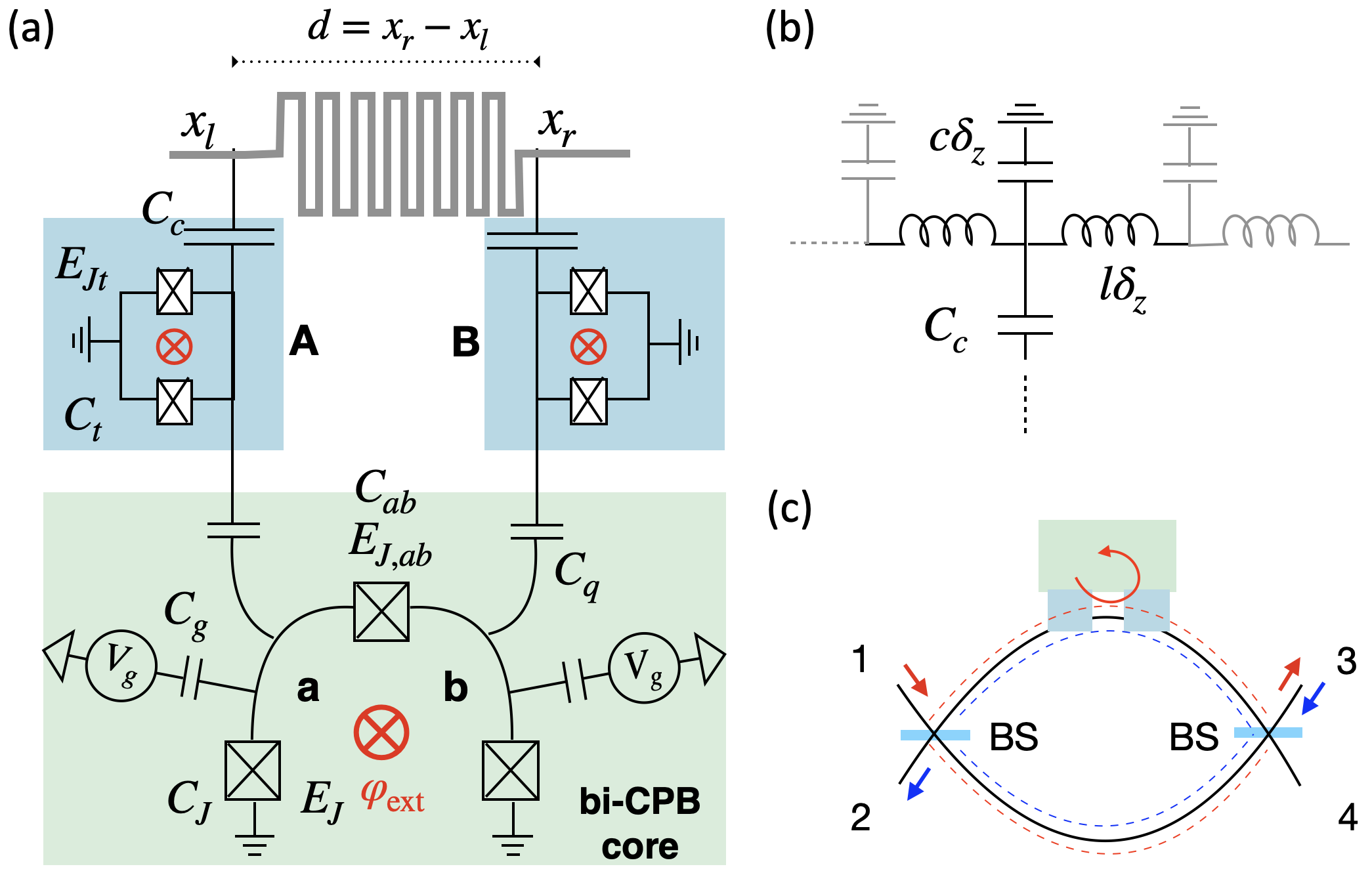
In this Letter, we develop an on-chip tunable broadband charge-insensitive chiral system illustrated in Fig. 1(a). The system is designed such that the (non-degenerate) excited states decay by only emitting photons in one direction, left or right. It has a core composed of two CPBs and an applied external flux (green box), and two transmons that connect the core to the waveguide at two separated locations, being reminiscent of a “giant atom” Frisk Kockum et al. 2014; Kockum 2021; Kannan et al. 2020. The core is essential for breaking TRS, while the transmons amplify the coupling to the waveguide and hence the bandwidth. Furthermore, by operating in a particular dark state configuration Arimondo and Orriols 1976 we show that excitation of the CPBs can be suppressed, such that the interface maintains the excellent coherence properties of transmons Place et al. 2021; Kjaergaard et al. 2020, while still exploiting the inherent breaking of TRS by the CPBs. The interface can directly be extended to realise a circulator for routing signals in large scale superconducting devices. Finally, the tunability of our chiral interface allows compensating fabrication variations as well as control of the operating frequency within a range of a few GHz.
Recent related proposals Guimond et al. 2020; Gheeraert et al. 2020 have used giant atoms formed by transmons and careful adjustments of parameters to realize unidirectional interactions with two degenerate levels, which decay in opposite directions. This degeneracy means that TRS is not broken, and the additional level provides a complication of the dynamics, in particular for non-perfect or partially chiral systems. Compared to these works, our chiral interface realizes the paradigmatic chiral model of a two-level system with chiral coupling, has tunable operating frequency, and more importantly, can be used for photonic circulators. During the final stages of this work, a different proposal suggested a chiral interface based on a specially designed waveguide and active driving Wang and rong Li 2021.

Preliminaries.
We first consider two coupled CPBs, “a” and “b”, which as a whole, has the ground state and a non-degenerate excited state . The transition between them is resonant with waveguide modes of wavenumber . We couple CPB-a and CPB-b to the waveguide at positions and , respectively [see Fig. 1(a)], resulting in coupling operators of the form , where is the photon annihilation operator, and is the CPB charge number operator. Within the rotating-wave approximation and perturbation theory, the decay from to left/right going photons depends on the magnitude of
| (1) |
This formula expresses the interference between excitation decaying through the left and right arms in Fig. 2(a), which depends on both the coupling matrix element at and the phase from waveguide propagation between them.
A chiral interface with a single excited state requires TRS to be broken since left and right propagation are connected by TRS, and a state invariant under TRS cannot distinguish these two possibilities. Breaking of TRS, however, may induce a phase difference between and allowing the cancellation of or for a suitable if .
Incorporating the chiral interface into one of the arms of a balanced Mach-Zehnder interferometer enables the construction of a four-port photonic circulator [Fig. 1(c)]. Suppose the scattering matrix of the chiral interface is with denoting the matrix element from wavenumber to . If the interface has ideal right-hand chirality, there will be no phase shift for the uncoupled left-moving photons (), whereas a phase shift is attained for the perfectly coupled right-moving photons (). This phase difference of implies that the Mach-Zehnder interferometer, shown in Fig. 1(c), can be balanced such that a right-moving photon incident in Port-1 exits through Port-3, whereas a left-moving photon incident in Port-3 exits through Port-2, realizing a circulator. We define the fidelity of the circulator as the product of the probabilities for these two inputs to exit through the correct port, which is given by
| (2) |
Obviously if and . In the Supplemental Material sp we show the system Hamiltonian and use the input-output formalism to derive the scattering matrix, based on which the fidelity (2) can be numerically evaluated for given setups.
The bi-CPB core.
TRS can be broken by Josephson junction rings threaded by magnetic flux Koch et al. 2010. Here we use an equivalent “bi-CPB core” sp depicted in the green box of Fig. 1(a). It has two CPBs denoted by “a” and “b”, which are assumed identical for now. Each CPB has a junction with Josephson energy and capacitance . The voltage source determines the offset charge through a capacitor with capacitance . We define . The two CPBs are connected by a Josephson junction with capacitance and Josephson energy . The external flux is made dimensionless by expressing it in units of with being the flux quantum. As depicted in Fig. 1(b), the transmission line waveguide is modeled by an infinite chain of coupled LC-oscillators with capacitance and inductance . The waveguide parameters are set by realistic impedance and the speed of light . The elementary length, , is determined by the lateral size of the coupling capacitor (or if using only the bi-CPB core).
At first, we consider coupling the bi-CPB core directly to the waveguide at , with device parameters given in the caption of Fig. 2. Particularly, we set corresponding to , which is comparable to the size of typical CPBs Wallraff et al. 2004. To suppress the dephasing caused by charge noise, the offset charge is fixed at the “sweet spot” where Vion 2002 and is the energy gap between the th excited state and the ground state of the core (the sweet spot must be excluded, because here particle-hole symmetry preserves TRS). The separation is selected so that .
In Fig. 2(a), we plot as a function of detuning from for and a few values of . The plot shows that the bare core can indeed acts as a chiral emitter, but suffers from several shortcomings. Firstly, the peak fidelity, , is sensitive to the exact value of , leaving the device performance highly sensitive to fabrication variation. Fabrication variations might be compensated by adapting the tunable flux . To examine this, we choose a representative corresponding to a 10% deviation from the ideal value and plot as a function of in Fig. 2(b). It shows that this tuning fails to make the maximal fidelity above 0.9. Furthermore, tuning changes , rendering this configuration inadequate for tasks where photon frequencies are fixed. Figure 2 also shows that the bandwidth is less than 1, which severely limits the functionality.
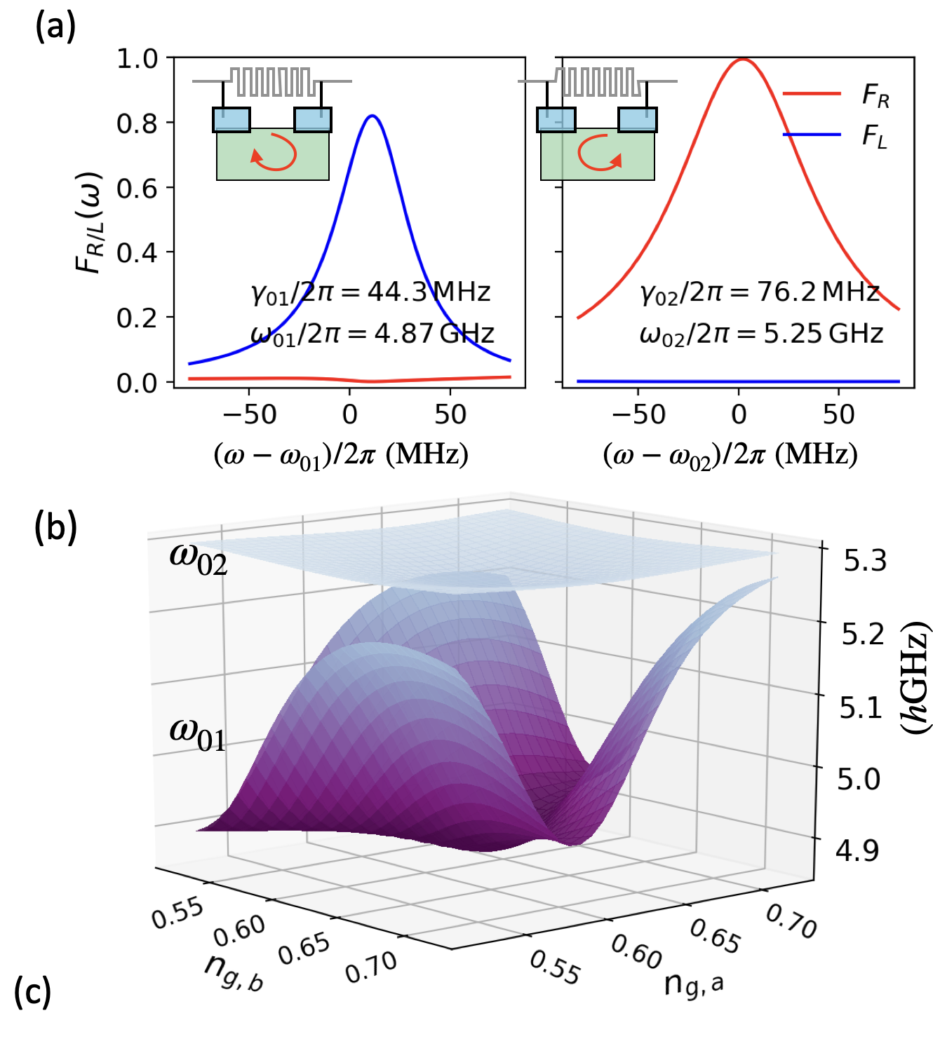
| 50 | 0.5 | 1 | 1 | 1 | 5.5 | 5 | 0.5 | 100 | 30 | 13 |
The transmon-coupled bi-CPB chiral photonic interface.
The bandwidth is limited by the weak interaction between the small CPBs and the waveguide excitations delocalized on wavelength scale. To overcome this, we propose to insert transmons, which have lateral size in between the CPBs and the photonic wavelength, as efficient mediators. Compared with similar proposals using microwave resonators Koch et al. 2007; Richman and Taylor 2021, transmons allow for stronger spatial confinement of excitations, and thereby larger couplings to the CPBs, while simultaneously maintaining sizable coupling to waveguides. A similar advantage could be achieved with high impedance elements Richman and Taylor 2021, but the transmons additionally allow wide tunability as discussed below. In Fig. 3(a) we plot as a function of the detuning to the first two excited states ( and ) for the CPB-transmon-coupled system. The device parameters used in the calculation are listed in Fig. 3(c), which are chosen to be representative for typical experimental situations and not fully optimized. Particularly, we have taken i.e., , corresponding to the lateral size of the transmon reported in Ref. Mirhosseini et al. 2019. Figure 3(a) shows that the bandwidth is significantly improved. However, while a left-hand chirality () is realized for (and ) – similar to the bare bi-CPB core – we observe the opposite chirality for (). This feature indicates the distinctness of the 2nd excited state. Below we use an approximate model to highlight multiple benefits brought by this state.
We assume that the two transmons, indexed by “A” and “B” in Fig. 1(a), are identical in parameters, and consider a restricted Hilbert space spanned by the ground state and the singly-excited states of either transmon-A,B, or the bi-CPB core, which will be denoted by , , and , respectively. The device Hamiltonian reads , where with and the energies of the 1st excited states of the core and the transmons, respectively. The interaction Hamiltonian is
| (3) |
where is the coupling strength. Using rotating-wave approximation upon , and restricting it to the reduced Hilbert space, we rewrite as
| (4) |
where is modified from and
| (5) |
with as in Eq. (1). The coupling between and yields the 1st excited state with energy and the 3rd excited state with energy ,
| (6) |
where with . The 2nd excited state is a so-called dark state Arimondo and Orriols 1976, which has no excitation on the core,
| (7) |
Despite being decoupled, still attains chiral property from the core. The constants , however, have different orders and signs in and , which lead to opposite chirality.
A more important observation is that the state does not contain the bi-CPB state . Thus, it is not affected by the CPB charge noise and keeps the charge noise insensitivity of the transmon qubits Koch et al. 2007. To illustrate this, Fig. 3(b) shows and as a function of the offset charges . The results are numerically evaluated from the complete Hamiltonian (see sp for details) using device parameters listed in Fig. 3(c). Figure 3(b) demonstrates that is significantly more stable than . The fluctuation of does not exceed its linewidth despite the large variations in . Thus, the offset charges need not be at the sweet spots, and can be used as control knobs to provide tunability.
Tunability of the chiral interface.
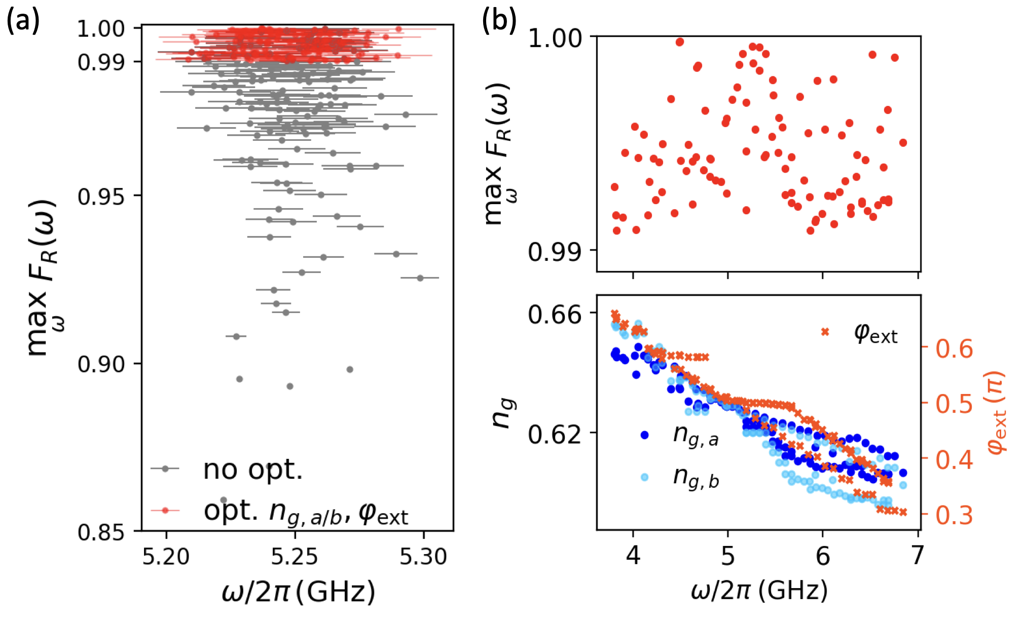
First, we demonstrate that by tuning and we can address issues of fabrication variation in the device parameters. To simulate realistic fabrication variations, we sample values of capacitance and CPB Josephson energy uniformly in intervals bounded by and , respectively, from the intended values listed in Fig. 3(c). The transmon Josephson energy is fixed at the intended values because they can be tuned in situ via flux-control. We collect 150 such “realistic samples”, which includes cases with asymmetries between CPB-a and CPB-b, and between transmon-A and transmon-B. In Fig. 4(a), we fix and at the optimal value for the ideal parameters, and show by grey points their individual maximal fidelity (vertical coordinate), frequency where the maximal fidelity is obtained (horizontal coordinate), and the bandwidth (horizontal error bar). While the performance is generally good, certain instances with poor chiral fidelity are observed. Next, for each sample that has a maximal fidelity less than 0.99, we search for values of and that improve the performance. The red points in Fig. 4(a) show the result of such optimization. We are always able to tune the maximal fidelity above . Additional details about how the maximal fidelity and bandwidth depend on and are given in the Supplemental Material sp.
Additionally, flux-tunable transmons Koch et al. 2007 enables tuning of the operating frequency of our device. We consider the parameters listed in Fig. 3(c) (including the separation ). For 100 values of between , we optimize the peak fidelity to be higher than 0.99 by tuning and . The results are presented in Fig. 4(b). It shows that for photons in a band of width, the same device can always be tuned to provide an excellent chiral interaction. This broad adaptability is rooted in the breaking of TRS. When we tune , changes and so does the phase with . Adjusting the flux , however, allows us to achieve complete destructive interference in one of the directions. Our chiral interface thus works in principle as long as ().
Discussion and conclusion.
The bandwidth for is about in Fig. 3(a). This is limited by the transmon decay rate, which is typically on the order of . The bandwidth can thus be directly enhanced by designing transmons with larger decay rates. We note however that as the decay rate approaches roughly a tenth of the transition frequency () the system reaches the ultra-strong coupling regime of waveguide QED Forn-Díaz et al. 2016 requiring a more advanced theoretical description Sanchez-Burillo et al. 2014; Shi et al. 2018.
Our interface relies on the 2nd excited state. This raises the concern that decay to the 1st excited state may jeopardize the performance. This transition is negligible for two reasons. First, the transition matrix element is tiny (vanishing in our simplified model ). Second, the waveguide mode density at is low. As a result, the decay rate to the 1st excited state is numerically found to be , which is much smaller than . Similarly, the intrinsic loss of the components involved can be made well below Barends et al. 2013; Place et al. 2021. This is much less than the decay rate to the waveguide and hence negligible sp.
In conclusion, we have shown that by introducing two transmons, a passive charge-noise insensitive chiral photonic interface can be build, based on a core consisting of CPBs and an external magnetic flux that breaks TRS. The interface has rich tunability, making it tolerant to experimentally relevant fabrication variations. The bandwidth of is a few tens of for realistic transmon parameters with decay rates typically around . With tunable transmons (SQUIDs), our design can be tuned in a band as wide as a few GHz. The lateral dimension of the entire circulator can be a few millimeters sp. These properties makes our chiral interface highly attractive for e.g., on chip routing of microwave signals Sliwa et al. 2015; Abdo et al. 2014; Abdo et al. 2019; Kerckhoff et al. 2015; Barzanjeh et al. 2017; Metelmann and Türeci 2018; Hoi et al. 2011; Kamal et al. 2011; Estep et al. 2014; Roushan et al. 2016; Chapman et al. 2019; Guimond et al. 2020; Gheeraert et al. 2020 as well as fundamental studies of chiral waveguide QED Ramos et al. 2014; Mirza and Schotland 2016; Mahmoodian et al. 2018; Mahmoodian et al. 2020.
Acknowledgements.
A. S. Sørensen thanks Peter Lodahl, Per Delsing and Göran Johansson for useful discussions. M. Kjaergaard gratefully acknowledges helpful and insightful discussions with Bharath Kannan. Y.-X. Zhang and A. S. Sørensen thank Jacob M. Taylor and Brittany Richman for insightful discussions. Y.-X. Zhang, M. Kjaergaard & A. S. Sørensen acknowledge financial support from the Danish National Research Foundation. M. Kjaergaard was also supported by Villum Fonden (grant 37467) through a Villum Young Investigator grant.References
- Gardiner (1993) C. W. Gardiner, Phys. Rev. Lett. 70, 2269 (1993).
- Carmichael (1993) H. J. Carmichael, Phys. Rev. Lett. 70, 2273 (1993).
- Ramos et al. (2014) T. Ramos, H. Pichler, A. J. Daley, and P. Zoller, Phys. Rev. Lett. 113, 237203 (2014).
- Mirza and Schotland (2016) I. M. Mirza and J. C. Schotland, Phys. Rev. A 94, 012302 (2016).
- Shen and Fan (2007) J.-T. Shen and S. Fan, Phys. Rev. A 76, 062709 (2007).
- Zheng et al. (2011) H. Zheng, D. J. Gauthier, and H. U. Baranger, Phys. Rev. Lett. 107, 223601 (2011).
- Mahmoodian et al. (2020) S. Mahmoodian, G. Calajó, D. E. Chang, K. Hammerer, and A. S. Sørensen, Phys. Rev. X 10, 031011 (2020).
- Yudson (1985) V. I. Yudson, Zh. Eksp. Teor. Fiz. 88, 1757 (1985).
- Lodahl et al. (2017) P. Lodahl, S. Mahmoodian, S. Stobbe, A. Rauschenbeutel, P. Schneeweiss, J. Volz, H. Pichler, and P. Zoller, Nature 541, 473 (2017).
- Hoi et al. (2011) I.-C. Hoi, C. M. Wilson, G. Johansson, T. Palomaki, B. Peropadre, and P. Delsing, Phys. Rev. Lett. 107, 073601 (2011).
- Blais et al. (2021) A. Blais, A. L. Grimsmo, S. Girvin, and A. Wallraff, Reviews of Modern Physics 93 (2021), 10.1103/revmodphys.93.025005.
- Roy et al. (2017) D. Roy, C. M. Wilson, and O. Firstenberg, Rev. Mod. Phys. 89, 021001 (2017).
- Caloz et al. (2018) C. Caloz, A. Alù, S. Tretyakov, D. Sounas, K. Achouri, and Z.-L. Deck-Léger, Phys. Rev. Applied 10, 047001 (2018).
- Sliwa et al. (2015) K. M. Sliwa, M. Hatridge, A. Narla, S. Shankar, L. Frunzio, R. J. Schoelkopf, and M. H. Devoret, Phys. Rev. X 5, 041020 (2015).
- Abdo et al. (2014) B. Abdo, K. Sliwa, S. Shankar, M. Hatridge, L. Frunzio, R. Schoelkopf, and M. Devoret, Phys. Rev. Lett. 112, 167701 (2014).
- Abdo et al. (2019) B. Abdo, N. T. Bronn, O. Jinka, S. Olivadese, A. D. Córcoles, V. P. Adiga, M. Brink, R. E. Lake, X. Wu, D. P. Pappas, and J. M. Chow, Nature Communications 10, 3154 (2019).
- Kerckhoff et al. (2015) J. Kerckhoff, K. Lalumière, B. J. Chapman, A. Blais, and K. W. Lehnert, Phys. Rev. Applied 4, 034002 (2015).
- Barzanjeh et al. (2017) S. Barzanjeh, M. Wulf, M. Peruzzo, M. Kalaee, P. B. Dieterle, O. Painter, and J. M. Fink, Nature Communications 8 (2017), 10.1038/s41467-017-01304-x.
- Metelmann and Türeci (2018) A. Metelmann and H. E. Türeci, Phys. Rev. A 97, 043833 (2018).
- Kamal et al. (2011) A. Kamal, J. Clarke, and M. H. Devoret, Nature Physics 7, 311 (2011).
- Estep et al. (2014) N. A. Estep, D. L. Sounas, J. Soric, and A. Alù, Nature Physics 10, 923 (2014).
- Roushan et al. (2016) P. Roushan, C. Neill, A. Megrant, Y. Chen, R. Babbush, R. Barends, B. Campbell, Z. Chen, B. Chiaro, A. Dunsworth, A. Fowler, E. Jeffrey, J. Kelly, E. Lucero, J. Mutus, P. J. J. O’Malley, M. Neeley, C. Quintana, D. Sank, A. Vainsencher, J. Wenner, T. White, E. Kapit, H. Neven, and J. Martinis, Nature Physics 13, 146 (2016).
- Chapman et al. (2019) B. J. Chapman, E. I. Rosenthal, and K. W. Lehnert, Phys. Rev. Applied 11, 044048 (2019).
- Koch et al. (2010) J. Koch, A. A. Houck, K. L. Hur, and S. M. Girvin, Physical Review A 82 (2010), 10.1103/physreva.82.043811.
- Wallraff et al. (2004) A. Wallraff, D. I. Schuster, A. Blais, L. Frunzio, R.-S. Huang, J. Majer, S. Kumar, S. M. Girvin, and R. J. Schoelkopf, Nature 431, 162 (2004).
- Müller et al. (2018) C. Müller, S. Guan, N. Vogt, J. H. Cole, and T. M. Stace, Phys. Rev. Lett. 120, 213602 (2018).
- Koch et al. (2007) J. Koch, T. M. Yu, J. Gambetta, A. A. Houck, D. I. Schuster, J. Majer, A. Blais, M. H. Devoret, S. M. Girvin, and R. J. Schoelkopf, Phys. Rev. A 76, 042319 (2007).
- i Carceller (2020) C. R. i Carceller, Chiral photon interaction mediated by a superconducting circuit QED, Master’s thesis, University of Copenhagen (2020).
- Richman and Taylor (2021) B. Richman and J. M. Taylor, PRX Quantum 2, 030309 (2021).
- Frisk Kockum et al. (2014) A. Frisk Kockum, P. Delsing, and G. Johansson, Phys. Rev. A 90, 013837 (2014).
- Kockum (2021) A. F. Kockum, in International Symposium on Mathematics, Quantum Theory, and Cryptography, edited by T. Takagi, M. Wakayama, K. Tanaka, N. Kunihiro, K. Kimoto, and Y. Ikematsu (Springer Singapore, 2021).
- Kannan et al. (2020) B. Kannan, M. J. Ruckriegel, D. L. Campbell, A. F. Kockum, J. Braumüller, D. K. Kim, M. Kjaergaard, P. Krantz, A. Melville, B. M. Niedzielski, A. Vepsäläinen, R. Winik, J. L. Yoder, F. Nori, T. P. Orlando, S. Gustavsson, and W. D. Oliver, Nature 583, 775 (2020).
- Arimondo and Orriols (1976) E. Arimondo and G. Orriols, Lettere Al Nuovo Cimento Series 2 17, 333 (1976).
- Place et al. (2021) A. P. M. Place, L. V. H. Rodgers, P. Mundada, B. M. Smitham, M. Fitzpatrick, Z. Leng, A. Premkumar, J. Bryon, A. Vrajitoarea, S. Sussman, G. Cheng, T. Madhavan, H. K. Babla, X. H. Le, Y. Gang, B. Jäck, A. Gyenis, N. Yao, R. J. Cava, N. P. de Leon, and A. A. Houck, Nature Communications 12 (2021), 10.1038/s41467-021-22030-5.
- Kjaergaard et al. (2020) M. Kjaergaard, M. E. Schwartz, J. Braumüller, P. Krantz, J. I.-J. Wang, S. Gustavsson, and W. D. Oliver, Annual Review of Condensed Matter Physics 11, 369 (2020).
- Guimond et al. (2020) P.-O. Guimond, B. Vermersch, M. L. Juan, A. Sharafiev, G. Kirchmair, and P. Zoller, npj Quantum Information 6 (2020), 10.1038/s41534-020-0261-9.
- Gheeraert et al. (2020) N. Gheeraert, S. Kono, and Y. Nakamura, Phys. Rev. A 102, 053720 (2020).
- Wang and rong Li (2021) X. Wang and H. rong Li, “Chiral quantum network with giant atoms,” (2021), arXiv:2106.13187 [quant-ph] .
- (39) See Supplemental Material for detailed derivations and additional plots.
- Vion (2002) D. Vion, Science 296, 886 (2002).
- Mirhosseini et al. (2019) M. Mirhosseini, E. Kim, X. Zhang, A. Sipahigil, P. B. Dieterle, A. J. Keller, A. Asenjo-Garcia, D. E. Chang, and O. Painter, Nature 569, 692 (2019).
- Forn-Díaz et al. (2016) P. Forn-Díaz, J. J. García-Ripoll, B. Peropadre, J.-L. Orgiazzi, M. A. Yurtalan, R. Belyansky, C. M. Wilson, and A. Lupascu, Nature Physics 13, 39 (2016).
- Sanchez-Burillo et al. (2014) E. Sanchez-Burillo, D. Zueco, J. J. Garcia-Ripoll, and L. Martin-Moreno, Phys. Rev. Lett. 113, 263604 (2014).
- Shi et al. (2018) T. Shi, Y. Chang, and J. J. García-Ripoll, Phys. Rev. Lett. 120, 153602 (2018).
- Barends et al. (2013) R. Barends, J. Kelly, A. Megrant, D. Sank, E. Jeffrey, Y. Chen, Y. Yin, B. Chiaro, J. Mutus, C. Neill, P. O’Malley, P. Roushan, J. Wenner, T. C. White, A. N. Cleland, and J. M. Martinis, Phys. Rev. Lett. 111, 080502 (2013).
- Mahmoodian et al. (2018) S. Mahmoodian, M. Čepulkovskis, S. Das, P. Lodahl, K. Hammerer, and A. S. Sørensen, Phys. Rev. Lett. 121, 143601 (2018).