Wireless/Mobile Multimedia Networks - COEN 332
Point to Point Ethernet Transmission Wireless
Backhaul Links Clustering
Puneet Kumar
SCU-ID: 00001424550
![[Uncaptioned image]](2106.14315v1/figures/University_logo.jpg)
Santa Clara University
Computer Networks: COEN-332
Department of Computer Science
California, USA
Audience
This document is intended to explain the Wireless Backhaul Links Clustering between point to point ethernet transmission links. With the word clustering the first thing comes to mind is bundling bunch of physical links to make a single logical link. While this definition holds true, it is imperative to know it’s implementation in conjunction with certain key factors. Upcoming 5G technologies where wireless backhaul links for point to point wireless Ethernet transmission may play a vital role in backbone networks, the proliferated needs of providing higher data rates should be met. With that demand, challenge of resilience, performance, scalability, maintainability, and manageability will rise as well. An optimal solution must be found which can reduce the failover points, ability to perform upgrade and downgrade with minimal downtime, and most importantly solution must overcome all the challenges faced in wireless link environment. A well tested approach has been presented in this paper which will accomplish all the mentioned points. This method will make the clustered wireless backhaul links more valuable and throughput will increase significantly.
This document targets audience of the class who are taking taken COEN - 332 (Wireless/Mobile Multimedia Networks), as fundamentals to understand this document was explained in the class. Additionally, lectures coverd layer 2/3 and wireless protocols for control, management and data plane required for this project report.
1. Introduction
Wireless Ethernet Transmission is a great way of extending the backbone network without deploying any physical network, specially fiber. This technology can be deployed in any form of topology and network. After FCC rolled out extra free frequency bands for instance 11GHz and 5GHz for commercial use, its demand is on rise [1]. Today Internet Service Providers (ISP), Enterprise Networking companies are relying on this technology a lot due to numerous factors such as Cost, Terrains, maintenance, easy to upgrade, and most importantly easy to troubleshoot. With upcoming 5G technologies where connecting 5G access points to the backbone networks will require to have a relay link in between to keep the data rate constant for long links. Wireless Ethernet Transmission technology will be handy to serve as a middleman in between backbone networks and 5G access points, where the link is just too long and data rate most likely will suffer without a Wireless Ethernet Transmission backhaul link. Another application of Wireless Transmission Network is campus. In campus, often it is hard to deploy fiber to extend the network to other buildings. Since it is in short range, so the interference wouldn’t matter that much. These backhaul links comes handy. Fiber gets dropped by the ISP to some places and then the network gets extended by these backhaul links.
In all these above-mentioned applications, we would need a higher amount of data rate with reliability and ability to be up for maximum amount of time. With the help of current MIMO technologies, specially with IEEE 802.11ac, if we have 2 RF chains, 4 Streams then the max data rate (Consider optimal RF conditions) is around 1Gbps [2]. With such high demand of data rate, 1Gbps will not be sufficient and hence will not be a suitable solution after all. In 5G the data rates will be way more than 1Gbps, deploying Wireless Ethernet Transmission Backhaul links in 5G will not suffice the purpose. An optimal solution is needed to make data rates higher with the existing infrastructure. Cluster will bundle multiple Wireless Ethernet Transmission Backhaul Links and will become a logically single link to provide higher data rates needed [3]. There will be a lot more to be explained and discussed with clustering, few are outlined below:
- •
Control Plane messages in unit selections and assigning duties
- •
Load Balancing across links
- •
High Availability
- •
Flow consistency
- •
State replication
- •
Configuration replication
- •
Management plane, Control plane, Data plane traffic handling
This solution will provide multiple Gbps data rate but also will provide a scalable, resilient, highly available, easy to upgrade with minimal disruption solution.
2. Concepts and Explanation
This section will explain the concepts and their relevance in clustering in wireless backhaul links.


2.1 Cluster Formation
Cluster will be a daemon running on each radio. Which will bind all the radios wireless links. This will appear one link for south and north bound devices and will aggregate the throughput. Cluster will have failover mechanism, load balancing and an algorithm for communication. Topology is needed to understand it as shown in figure 2.2 and figure 2.3 which shows the difference between physical topology and the logical topology.
2.2 Bootstrap Configuration and Cluster Members
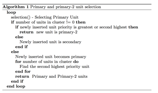
A unit consists of access-point and station. Each unit requires minimal bootstrap configuration which includes cluster name, cluster control link interface, management cluster link interfaces, data path link interfaces and local pool of IP address reserved for clustering. The first unit configured as a bootstrap configuration will be primary unit and rest become “secondaries”. These are initial roles; The primary unit assignment will also depend on the priority set in the bootstrap configuration. Priority can go from 1-100, where 1 is the highest priority. All other members are secondary units except one unit with second highest priority will be primary-2 and secondary both. Algorithm (figure 1.1) shows the complete scenario. In typical scenario, the very first unit added becomes the primary, it is because so far this is the only unit present in the cluster. Apart from bootstrap configuration, all configuration is on primary only; replication of configuration on secondary unit starts. When it comes to physical assets, for instance interfaces, primary’s configuration is mirrored to secondary unit. For example, if Ethernet 1 is configured as inside and Ethernet 2 is configured as outside, then these interfaces on secondary unit will be inside and outside respectively. Primary unit selection is based on request message which consists of priority set by user. As soon as a new unit is joined in the cluster, an election request will be sent on a multicast address 224.1.0.10 which is reserved for this purpose. All units in cluster will listen to this IP and only primary unit at that moment will reply to the newly joined unit. If the priority of newly joined unit is greater than the primary unit then newly joined unit will set itself to primary (Please see figure 2.1). If newly joined unit doesn’t receive any response back from primary unit then it sets itself and sends a multicast message to 224.1.0.11 which will force every unit to set them to secondary. In the case of tie of priorities (especially the highest priority), different parameters such as unit name and serial number are used to determine the primary unless it is down or stops responding for some reason, this will trigger a new unit selection


2.3 Cluster Interfaces
All the wireless backhaul links can either be configured as Spanned EtherChannel or Individual interfaces. All links has the configured one type only. Spanned EtherChannel is recommended. One or more links can be grouped into Spanned EtherChannel that spans all links in the cluster. Both routed and transparent modes are present in Spanned EtherChannel. A single IP address is provided to routed interface if the EtherChannel is configured in routed mode, on the other hand, transparent mode is something when we have an IP assigned to BVI (Bridge virtual Interface) not to the member interface of bridge group. This will inherit the load balancing as a part of basic operation. In Spanned EtherChannel shows in figure 2.4, we will combine all the interfaces into a single logical link using LACP. This interface will become a bundle of all the interfaces attached to it. This EtherChannel will spans all units in the cluster. It is recommended as EtherChannel aggregates traffic from all the available active interfaces in the channel. In this mode, all units use the same VIP (Virtual Internet Protocol address) assigned to the cluster and the same MAC used in EtherChannel of the cluster. Another mode is individual routed mode (Figure 2.5) where each link will maintain its own IP on each data interface. Since this approach doesn’t use any aggregation link to load balance and implement any fail over, dynamic routing is needed to load balance. In individual mode, each radio maintains its own routing adjacency. The disadvantage of this is slower convergence and higher processor utilization due to each unit maintaining its own routing table. In spanned EtherChannel mode, the primary access point and station runs dynamic routing. Routing and ARP tables are synchronized to the secondary units. A round trip time of 20ms and maintaining a reliable cluster control link functionality is important. To make sure that this condition is intact, a ping pong icmp messages goes from every secondary units to master units. Cluster control link is the most important link in the cluster and will have a dedicated interface for cluster control link. If a cluster control link is down, then the cluster will be down and it must be brought up by solving the problem which led it to down and then joining them one by one manually.
2.4 Monitoring units
To make sure all units are healthy and interfaces are up and running, a monitoring system is placed. Primary unit is responsible to monitor every secondary unit by sending a keepalive message periodically over the CCL (Cluster Control Link), this monitoring period is configurable. In the event of unit health check failure, it will be removed from the cluster. Every unit is supposed to send a keepalive message (UDP multicast packet) (Figure 2.10 to primary unit. Message format:
- •
Keepalive message header
- –
Type
- –
Version
- –
Length
- –
- •
Selection Info Component
- –
Unit Priority
- –
Serial Number
- –
Role (Primary Standby or Secondaries)
- –
- •
Radio Info Component
- –
Mode (Spanned EtherChannel or Individual Router Interface
- –
Radio Type (Access Point or Station)
- –
SNR
- –
Load Balancing Weight
- –
Here type is the keepalive (CLUSTER_KEEPALIVE). Version is 1 and length is the length of the message not including the header. The message has two more sections apart from the header. Section info component and Radio Info component. Figure 2.7 shows the message header. Here type is the SELECTION_INFO_COMP, length is the length of the selection info component. Unit priority is the priority assigned to unit while configuring cluster. Serial Number of the unit and Role of the unit whether it is Primary standby or a secondary unit. This section will let primary unit know about configurations of other units.
Figure 2.8 shows the radio info component message header. Here the type is RADIO_INFO_COMP. Length is the length of radio info component. It includes Mode operation whether it is spanned EtherChannel or Individual router interface. If primary unit finds that received packet has mismatch of mode of operation, then it excludes the unit from cluster and sends a unicast message to forcefully make the unit leave cluster. A high level message flow is depicted in figure 2.9.
2.5 Monitoring Interfaces and failure status
As soon as the health monitoring is turned on, all physical interfaces are monitored, including the main EtherChannel and redundant interface. An option will be provided to user to disable the health monitoring per interface. For instance, an EtherChannel is considered to be failed if all the units in the EtherChannel are failed. If this happens, the EtherChannel will be removed from the cluster but this will depend on the minimal port bundling settings. For a single unit, it will be considered removing from the cluster if all monitored interfaces fail. The amount of time removing a unit from the cluster will depend on the type of interface and whether a unit is established or just joining the cluster. For any EtherChannel spanned or not, if an interface is down on an established member, primary unit removes it after 9 seconds. For first 90 seconds, primary unit doesn’t monitor any interfaces for the unit which just joined the cluster. This means a primary unit will not remove it if the interface state changes during that 90 secs. In non-EtherChannel, the unit is removed in 500 ms regardless of the member state. In the case of failure of a unit, the connection belongs to that unit is seamlessly transferred to other units and state information for the traffic flows are shared over the CCL (Cluster Control Link). In case of primary unit failure itself, other member with highest priority (Which means unit with the lowest number priority) takes over. Failed primary unit, after recovery automatically tries to join the cluster. If rejoining the cluster of primary unit is failed then all data interfaces are shut down and only management interface can receive and send traffic. This management interface remains up using the IP address the unit received from the cluster IP pool.
2.6 Cluster Rejoining
The primary factor to join back a unit after being removed from the cluster is the reason why the unit was removed. There are three methods how a unit can rejoin the cluster.
- •
Failed cluster control link when initially joining—After the problem is resolved with the cluster control link, unit must be manually rejoined the cluster by re-enabling clustering at the console port by entering cluster group name, and then enable.
- •
Failed cluster control link after joining the cluster—Unit automatically tries to rejoin every 5 minutes, indefinitely. This behavior is configurable.
- •
Data Interface Failure - Unit will try maximum of 4 attempts on each 5 minute to rejoin the cluster. After resolving the issue with the data interface, a manually enabled clustering is required by entering cluster group name. This behavior is configurable.

| Traffic | State Support | Nodes | ||
|---|---|---|---|---|
| Up Time | Yes |
| ||
| ARP Table | Yes |
| ||
| MAC Address Table | Yes |
| ||
| User Identity | Yes |
| ||
| SNMP Engine ID | No | —————————— | ||
| VPN Site-Site | No | —————————— |
2.7 Replication of Data path connection state
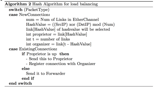
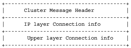
There is one owner and one backup owner for every connection in the cluster. Ownership doesn’t get transferred to backup owner in case of a failure instead a provision of TCP/UDP state information gets stored in it so that the connections can be transferred seamlessly. If for some reason the owner becomes unavailable, the very first unit to receive packets from the connection contacts the backup owner for the relevant connection state and then the backup owner becomes a new owner for this connection. Obviously, there would be some traffic which would require information above the TCP or UDP layer. Replication message is defined below. Cluster message header is already defined in figure 2.6. In the type field of figure 2.14, type field will be mentioned in CLUSTER_REPLICATION, version will be 1 and length is the length of the packet apart from the cluster message header. Often the traffic will be directed by the original unit where the traffic is flowing. Often UDP/TCP or higher layer information not needed to be transferred to the backup unit or in case of transfer to back up unit the traffic could be from the same origin and destined to the same destination. Separating the IP layer info (message shown in figure 2.15 from the higher layer can give flexibility to just check the source and destination IP and not needed to open the rest of the packet. This will make the transfer faster. Upper layer connection info (Message shown in figure 2.11 will contain vital information about Upper layer as shown below. Most of the time, the information doesn’t change and failover will only have to see the layer-3 packet and forward the upper layer information. Also, table 2.1 shows what extra information in preserved in connection and its transfer.


2.8 Cluster Management
To manage the cluster, a separate network must be created apart from cluster control network. A spanned EtherChannel or individual interfaces can be used as management network. Even if spanned EtherChannel is used for data still for management purposes recommended approach is individual interface. In it each unit can be connected directly to individual interfaces (if necessary), on the other hand a spanned EtherChannel interface only allows to be connected to primary unit via remote connection. In case of individual interface, cluster IP address is fixed which always belongs to the current primary unit. A range of IP address can be configured for each unit which of course includes the current primary which can use a local address from the range. Having a main cluster IP provides management consistency access to an address; In case of role change of primary unit to other unit in cluster, this main IP moves to the new unit which will result in the seamless transfer of the management of the cluster. For routing, the local IP is used and it is also useful for troubleshooting. For an instance, a cluster is managed by the main cluster IP and this IP is always attached to the current primary unit but to manage an individual member, a local IP can do the job. There are outbound management traffic service like syslog, TFTP etc, each unit (includes primary unit too) uses this local IP to connect to the server. In the event of Spanned EtherChannel interface, one main IP is configured which is attached to the primary unit. Secondary units will not be allowed to connect directly using the EtherChannel interface and hence an individual interface is recommended for configuring the management interface and user will be easily able to connect to single unit.
2.9 Load Balancing Method
Spanned EtherChannel have bundled links which load balances and failovers in case of a link failure. There is more than one physical links are bundled into the Spanned EtherChannel (At Max 6), the primary aim is to have traffic across all the links equally however a IP stickiness is desired as well. Packets with same destination and source IP should take the same path every single time for IP stickiness to be maintained. This will give consistency and ease of troubleshoot in case of data packet inspection or loss. In the load balancing algorithm for EtherChannel, a hash function (Algorithm shown in figure 2.12 calculates a hash value which determines which link packet will go out. The algorithm for hashing will be “symmetric” which means the packet from both the directions will have the same hash, and will be sent to the same unit in spanned EtherChannel. By default, Source IP and destination IP are being used and it is recommended too. Another restriction is to use same type of radio when connecting the units to the switch so that hashing algorithm applied to all the packets. In individual routed mode load balancing, each radio will maintain its own IP address. One method of load balancing is Policy Based Routing. Traditional Policy based Routing is based on policy which is applied to ingress and egress interface based on access-list which will allow certain type of traffic to be passed. Policy is a map which allows certain type of traffic to be passed from certain units. Since it is static, chances are it may not achieve the optimal load balancing results. Recommended way of configuring policy is to make sure that forward and return packets of a connection are directed to the same physical unit.
2.10 Connection Management and Formation
Roles of connections determine how they are handled in high availability and normal operation. Connections can be load balanced among multiple members of the clusters too. For connection management, we will distribute the unit roles of three different type:
- •
Proprietor
- •
Organizer
- •
Forwarder
from the connection, the director chooses a new owner from those units from the connection, the director chooses a new owner from those units. Function of Organizer is to handles owner lookup requests which are coming from forwarders and maintain a connection state to serve as a backup if the owner fails. When a Proprietor receives a new connection, based on our hashing algorithm of source/destination IP a director is chosen and a message is sent to the organizer to register the new connection. If packet arrives at any unit other than the owner then unit queries the director about which unit is the owner so that forwarder can forward the packet to the owner. A connection has only one Organizer. If an Organizer fails, the owner chooses a new Organizer. Function of “Forwarder” is to forward packets to Proprietor. If packet received by Forwarder doesn’t own by it, it goes ahead and queries the organizer for the proprietor and then it establishes a connection with the Proprietor so that Forwarder can forward packets received by it in future. An Organizer can also be a forwarder. Let’s take an example, if a Forwarder receives a SYN-ACK packet, it can derive the Proprietor directly from a SYN cookie in the packet, so it does not need to query the Organizer. There is a used case when TCP sequence randomization is not enabled or disabled intentionally, SYN Cookie is no longer useful and query to Organizer is required. For short lived flows such as ICMP, DNS etc, instead of querying, the forwarder immediately sends the packet to the Organizer, which then sends them to the Proprietor. A connection can have more than one forwarder. A good load balancing algorithm is needed where there are no forwarders and all packets of a connection are received by the proprietor, our ECMP in Spanned EtherChannel interface provides this. When a new connection is directed to a member of the cluster via load balancing, that unit owns both directions of the connection. For any connection, if packets are arrived at a different unit, they will be forwarded to the owner over CCL (Cluster Control Link). If more optimization is needed then an external load balancing needs to be in place for both directions of the flow to arrive at the same unit, it is redirected back to the original unit.



2.11 Data Flow
Figure 2.13 shows the data packet flow. Proprietor role is assigned to unit that initially receives the connection. The owner maintains the TCP state and processes packets. A connection has only one owner. If the original owner fails, then when new units receive packets will become Proprietor.
- •
The SYN packet originates from the client and it is delivered to one Unit (based on the load balancing mechanism). This unit becomes the Proprietor, proprietor creates the flow, encodes owner information into a SYN cookie, and forwards the packet to the server.
- •
Since the forwarder doesn’t own the connection, it uses SYN cookie to decode the owner information, it creates a forwarding flow to the owner, and forwards the SYN-ACK to the Proprietor. The Proprietor sends a state update to the Organizer, and forwards the SYN-ACK to the client.
- •
The Organizer receives the state update from the Proprietor, creates a flow to the Proprietor, and records the TCP state information as well as the Proprietor. The Organizer acts as the backup owner for the connection.
- •
After this any subsequent packets delivered to the forwarder will be forwarded to the proprietor. If packets are delivered to any additional unit then a query to director is needed for the owner and to establish a flow. Any state change for the flow result will be a state update from the proprietor to organizer.
- •
Unbalanced flow distributions resulted from load balancing capabilities of the upstream and downstream network can be mitigated by redirect new TCP flows to the other units, this can be configured while no existing flows will be moved to the other units.

3. Simulation Model
We simulated wireless backhaul link by using CNET[4] (shown in figure 3.1. CNET use 5Ghz bandwidth. CNET provides APIs (predefined) to set up its own simulation model. We used customized parameters below for simulation.
- •
1472Bytes - MTU Size
- •
1 - 2 Gbps Bandwidth
- •
5GHz - WLAN Frequency
- •
20dBm - WLAN Tx Power
- •
10dBi - WLAN Tx Antenna Gain
- •
10dBi - WLAN Rx Antenna Gain
These tests are simulated while keeping some parameters constant.
- •
80Mhz - Channel Width
- •
2 (Number of Streams - 4) - No. of channels
- •
30dBm - Tx Power
- •
36dB - Signal to Noise Ratio (SNR)
- •
0.5% - Packet Error Rate (PER)
- •
(-17) - Error Vector Magnitude (EVM)
- •
8 - MCS Index
- •
256QAM - Modulation Technique
PHY rates demonstrated how much ethernet frames can propagate through the wireless backhaul links in optimal conditions. Additionally, MAC rates are more fair comparison to the TCP throughput than PHY rates. We already mentioned in previous section about how MAC rates are calculated. After changing PHY rates, we will note how MAC rates are changing as well. This will demonstrate the real world scenario about MAC rates, depends on different RF condition.
We used iperf for performing TCP throughput test. Iperf gives us mechanism to customzie our TCP parameters. We will set our iperf parameters as: number of TCP Connection – 50 and TCP Window size - 64K. PHY Rates shows how much Ethernet frames can cross the wireless link under optimal condition. However, MAC rates are dependent on PHY Rates and can give us fair idea of how TCP throughput varies. Formula for MAC rates:
| (3.1) |
Where:
Tx MAC Rates = MAC
Tx PHY Rates = PHY
MAC Duty Cycle = Cycle
Tx MAC Efficiency = Efficient
PHY Cycle Efficiency = MAC
Rx MAC Rates = MAC
Rx PHY Rates = PHY
Rx MAC Duty Cycle = Cycle
MAC Efficiency = Efficiency
A simple iperf test is performed to collect the TCP throughput rates. Iperf provides room to define TCP parameters. For the sake of simplicity, we will set our iperf parameters as defined below:
- •
Number of TCP Connection – 50 and TCP Window size - 64K


4. Conclusion
With CNET APIs infrastructure, and changing duty cycle and efficiency, we could simulate the wireless backhaul links. Different scenarios were taken into account. Figures demonstrated that throughput increased. Additionally, one unit was brought down and we could see the effect on throughput. In figure 3.2, MAC rates and throughput are shown. This is without clustering and units are working independently and transmission. These PHY rates are being used in the rest of the test cases we captured. Individual units give throughput around 0.8 to 1.3 Mbps. In figure 3.3, the throughput is with clustering when all units are working together and projecting as a single logical unit. Figure 3.4 shows throughput when a single unit is removed. Figure 3.5 results shows that throughput got increased and latency was under 20 ms from primary to secondaries. When we have one unit removed/failed the throughput got decreased considerable. Throughput shown in the result proves that with clustering we have more resilient, robust, and highly available solution for providing higher throughput. Even if we have one unit removed, throughput doesn’t decrease significantly
Bibliography
- [1] D Goovaerts. Fcc unanimously opens nearly 11 ghz of spectrum for 5g, 2016.
- [2] Mimosa Networks. Data Sheet B5c/B5 product, 2020.
- [3] Glenn Parsons. IEEE 802.1X-2020 - IEEE Standard for Local and Metropolitan Area Networks–Port-Based Network Access Control, 2020.
- [4] Chris McDonalds. Cnet simulator. https://www.csse.uwa.edu.au/cnet/.
*