Nanomechanical Dissipation and Strain Engineering
Abstract
Nanomechanical resonators have applications in a wide variety of technologies ranging from biochemical sensors to mobile communications, quantum computing, inertial sensing, and precision navigation. The quality factor of the mechanical resonance is critical for many applications. Until recently, mechanical quality factors rarely exceeded a million. In the past few years however, new methods have been developed to exceed this boundary. These methods involve careful engineering of the structure of the nanomechanical resonator, including the use of acoustic bandgaps and nested structures to suppress dissipation into the substrate, and the use of dissipation dilution and strain engineering to increase the mechanical frequency and suppress intrinsic dissipation. Together, they have allowed quality factors to reach values near a billion at room temperature, resulting in exceptionally low dissipation. This review aims to provide a pedagogical introduction to these new methods, primarily targeted to readers who are new to the field, together with an overview of the existing state-of-the-art, what may be possible in the future, and a perspective on the future applications of these extreme-high quality resonators.
I Introduction
Nano- and micro-mechanical resonators have a broad range of applications, from micro-electromechanical sensors (MEMS) Bogue 2013; Villiers et al. 2016, to radio- and microwave frequency filters and clocks Massel et al. 2011; Nguyen 2007, future computing technologies Pechal et al. 2018, and tests of fundamental science Forstner et al. 2020; Vinante et al. 2017. As sensors, they have been applied in inertial and gyroscopic navigation Krause et al. 2012; Fan et al. 2019; Shaeffer 2013; Dabove et al. 2015; Cook et al. 2018; Ayazi and Najafi 2001; Zhou et al. 2021, gas and biochemical sensing Muruganathan et al. 2018; Eom et al. 2011; Carrascosa et al. 2006, atomic force microscopy, magnetometry Forstner et al. 2014; Li et al. 2020; Forstner et al. 2012, acoustic and temperature sensing Basiri-Esfahani et al. 2019; Firdous and Potter 2020; Purdy et al. 2017; Singh and Purdy 2019; Westerveld et al. 2021, single protein mass spectroscopy Hanay et al. 2012 and single molecule detection Chien et al. 2018. They are key elements for future computer technologies based on nanomechanical motion Mauranyapin et al. 2021, and for future quantum information technologies due to their ability to mediate various quantum degrees of freedom Clerk et al. 2020; Hadfield and Johansson 2016; Chu et al. 2017; Bowen and Milburn 2016. Recently, high quality factor nanomechanical resonators have enabled a broad range of new quantum physics, such as cooling of a nanomechanical oscillator to its quantum ground state Chan et al. 2011; Teufel et al. 2011a, entanglement with microwave fields Palomaki et al. 2013; Romero-Sánchez et al. 2018 and entanglement between mechanical resonators Ockeloen-Korppi et al. 2018.
In nearly all applications performance is dependent on the mechanical energy dissipation rate , where a small dissipation rate is desirable to both isolate the resonator from environmental noise sources and to maintain coherent oscillation for an extended time. A more coherent resonator offers better stability and suppression of noise sources, thus allowing for cleaner and more precise readout Walls and Vig 1995; Cleland and Roukes 2002; Aspelmeyer et al. 2014. The dissipation rate is often compared to the mechanical resonance frequency via the mechanical quality factor Schmid et al. 2016,
| (1) |
The quality factor quantifies the number of coherent oscillations of the resonator before it decays to roughly 4% percent of its original amplitude. As also expressed in Equation (1), the quality factor can equally be described as the quotient of stored energy in the resonator to the energy dissipated per cycle of oscillation .
Recent years have seen dramatic progress in our understanding of the fundamental origins of the primary dissipation mechanisms relevant to nanomechanical resonators. From this, new engineering techniques and strategies have emerged to suppress the dissipation. These new techniques include acoustic isolation Tsaturyan et al. 2014; Ghadimi et al. 2017, soft clamping Tsaturyan et al. 2017; Beccari et al. 2021, dissipation dilution Fedorov et al. 2019 and strain engineering Ghadimi et al. 2018. Leveraging these techniques has enabled quality factors approaching one billion at room temperature in amorphous nanomechanical resonators Ghadimi et al. 2018; Tsaturyan et al. 2017; Beccari et al. 2021, together with predictions that even higher quality factors should be possible using crystalline resonators Romero et al. 2020; Ghadimi et al. 2018. This provides the prospect of orders-of-magnitude sensitivity enhancements in nanomechanical sensors Ekinci et al. 2004, extremely narrow nanomechanical filters Sun et al. 2012, high density nanomechanical memories Merklein et al. 2017 and delay lines that can passively store information for many minutes Roodenburg et al. 2009, as well as fundamentally new technologies such as nanomechanical computer Pechal et al. 2018 and quantum information processors Kotler et al. 2021; Mercier de Lépinay et al. 2021. The purpose of this review is to provide an introduction to these new techniques, and an outlook on applications and what further advances may be possible in future.
I.1 Fundamentals of a Nanomechanical String Resonator
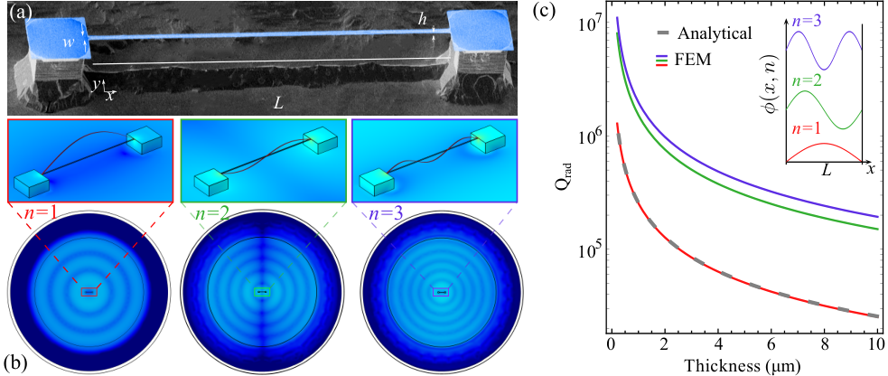
In this review, to provide concrete examples throughout, we consider the case of a string resonator under tensile stress. At the most basic level, string resonators are analogous to guitar strings. They feature two clamping points and are sufficiently thin such that their resonances have roughly sinusoidal eigenmodes (or modeshapes), for the most part unaffected by the presence of the clamping points. The fundamental mode of a string resonator has nodes only at the clamping points, and is labelled by the mode number , whereas higher order modes have increasing numbers of nodes. An example of a string resonator is shown in Figure 1 together with the shape of its first transversal modes. The mode shape of a mechanical resonator defines a normalised amplitude of displacement of each spatial element of the resonator. For a string, it is generally assumed to be a scalar field, with displacement only occurring in the vertical direction, defined here as the direction. Moreover, for a sufficiently thin string resonator with uniform width the displacement is constant across its width Fedorov et al. 2019; Ghadimi 2018, here defined to be the direction. For simplicity we take these approximations for the majority of this review, so that the -th string eigenmode can be simplified to a unidimensional problem , where is the longitudinal position along the string. This assumption is reasonable so long as the string has a uniform width and that its length is much larger than both its width and its thickness ().
Under the approximations outlined in the previous paragraph, the characteristic resonance frequencies, or eigenfrequencies, of a string resonator of length and cross-section are given by Schmid et al. 2016
| (2) |
where is the wavenumber for the mode , is the stress of the string, is the geometric moment of inertia, and and are the Young’s modulus and density of the material respectively. Assuming a string with a rectangular cross-sectional area so that , the moment of inertia is given by .
II Mechanisms of elastic energy dissipation
Micro- and nano-mechanical resonators are simultaneously subjected to various damping mechanisms. The magnitude of each mechanisms contribution to the resonator’s total dissipation typically depends on a large number of variables, often interconnected. These include the resonator’s geometry, material, vibrational mode, resonance frequency, and surrounding pressure and temperature, among others. Identification and mitigation of these dissipation mechanisms in this multivariate space is a non-trivial task.
The dissipation mechanisms can be divided into intrinsic dissipation, , internal to the resonator itself, and extrinsic dissipation (also termed external dissipation), , related to the resonator’s interactions with its environment. The total quality factor of the resonator can then be expressed as
| (3) |
where and are the intrinsic and extrinsic quality factors, respectively Tsaturyan 2019; Ghadimi 2018. In the following we introduce the various forms of intrinsic and extrinsic dissipation mechanisms common to micro- and nano-mechanical resonators, their dependencies on system parameters, and how extrinsic mechanisms may be suppressed.
II.1 Intrinsic Dissipation
A resonator’s intrinsic dissipation can be attributed to various processes occurring in the material’s bulk and surface Villanueva and Schmid 2014; Mohanty et al. 2002; Jinling Yang et al. 2002. This energy loss, inherent to the resonator, can be further divided into processes associated with the internal friction of the material and those more fundamental, unrelated to the frictional damping Schmid et al. 2016. The internal friction of a resonator is determined by the material type and quality, commonly more significant in amorphous and defect-rich materials Ashby 1989. As the resonator’s atoms move during vibration, friction between them gives rise to damping and energy loss Zener 1938. This intrinsic friction can stem from defects, discontinuities in crystalline materials, or molecular chain movements in amorphous materials. Frictional loss is commonly modelled as a lagged response to a coherent excitation, given by the Zener’s model of anelastic materials Zener 1937; Zener 1938.
Independent of this frictional loss, additional sources of intrinsic dissipation exist in nanomechanical resonators. These loss processes arise from the coupling of the resonator’s oscillating strain field to temperature fields or two-level systems Schmid et al. 2016; Tsaturyan 2019. Various causes of fundamental loss, such as thermoelastic damping, Akhiezer damping and loss to two-level systems, have been well studied Lifshitz and Roukes 2000; Kunal and Aluru 2011; Ghaffari et al. 2013; Faust et al. 2014; Rodriguez et al. 2019; Chakram et al. 2014. For a more thorough explanation of the various intrinsic dissipation mechanisms, refer to Refs. Schmid et al. 2016; Joshi et al. 2014; Imboden and Mohanty 2014.
II.2 Extrinsic Dissipation
Extrinsic dissipation can include gas damping, clamping loss, electrical charge damping and magnetomotive damping among other forms of dissipation Schmid et al. 2016. The total extrinsic quality factor is given in terms of the quality factors of these various damping mechanisms as
| (4) |
where the subscript labels the different mechanisms.
In applications where the resonator must interact with a surrounding medium, such as biochemical sensing Etayash et al. 2016; Fritz et al. 2000, acoustic sensing Basiri-Esfahani et al. 2019 and hydrodynamic experiments Ekinci et al. 2010; Kara et al. 2015, medium interaction damping is often the primary source of damping Naesby et al. 2017. As the name suggests, this loss arises from the interaction between a resonator and its surrounding medium. This medium, usually gas or liquid, damps the resonator’s motion through the exchange of energy during molecular collisions or viscous interactions Schmid et al. 2016; Sader 1998.
Where the application does not depend on interactions with the surrounding medium – such as inertial sensing Shaeffer 2013; Ekinci et al. 2004, nanomechanical circuitry Hatanaka et al. 2014; Romero et al. 2019 or quantum information applications Patel et al. 2018; Pechal et al. 2018, medium losses can be straightforwardly eliminated by placing the resonator in vacuum Naesby et al. 2017; Verbridge et al. 2008a. In this case, clamping losses are generally the dominant source of external loss. Clamping losses, also known as radiation loss, arise from the modulation in strain at the clamping (or anchor) points at which the oscillating resonator is attached to its substrate. As a resonator oscillates it pulls on the clamping points, inducing strain and subsequent acoustic waves Photiadis and Judge 2004. These acoustic waves radiate outward into the substrate carrying away energy that was previously stored in the resonator. The magnitude of clamping loss is dependent on both the impedance and mode matching between the resonator and substrate, as well as the geometry of the resonator Schmid et al. 2016; Cross and Lifshitz 2001. Clamping loss has even been found to be sensitive to the way in which a chip is mounted, whether that be adhesive bonding, mechanical clamps or resting unclamped under gravity Wilson et al. 2009; Schmid et al. 2011; Wilson.
II.3 Suppressing Clamping Loss
A range of techniques have been developed to suppress the radiation of acoustic energy at clamping points. Generally, they involve either increasing the impedance mismatch between the wave in the resonator and that in the substrate Norte et al. 2016; Reinhardt et al. 2016, acoustic wave bandgaps Tsaturyan et al. 2014; Yu et al. 2014; Ghadimi et al. 2017; Tsaturyan et al. 2017, or acoustic filters based on nested structures Weaver et al. 2016; Romero Sanchez 2019; Nielsen et al. 2017.
II.3.1 Impedance Mismatch and Clamping Loss of a String Resonator
In the case of a stressed string resonator, clamping loss occurs at each of its rigid clamping points, as portrayed in Figure 1(b). The magnitude of this energy loss is determined by the ease at which acoustic energy stored in the string can propagate into the substrate. Due to the large size and mass difference between the string and its substrate, a large impedance mismatch exists at the connecting junction. The impedance mismatch causes a partial reflection of acoustic waves at the interface. The acoustic waves that do manage to travel through the junction carry some fraction of the total acoustic energy away from the resonator. Analytical approximations of radiation loss, and the quality factor associated with this loss exist, and rely on finding the density of states overlap between the resonator and substrate modes Cross and Lifshitz 2001.
Previous works deriving clamping loss consider only a single clamped Photiadis and Judge 2004 or unstressed string Cross and Lifshitz 2001. An exact analytical solution for a stressed string has not been derived but is known to scale with length and width of the resonator as Schmid et al. 2011; Cross and Lifshitz 2001. Commonly the clamping loss of string resonators is calculated using finite element method (FEM) solvers Ghadimi et al. 2017; Ghadimi 2018. An advantage of using FEM solvers is the ability to alter the geometry of the clamping points and see its effect on without needing to update or create new analytical models. In Figure 1(c) we find based on finite element method solvers for the first three transverse modes and find the fundamental mode to agree well with the analytical approximation described in Ref. Romero et al. 2020. This analytical fit is a modification to the approximations described for a stressed membrane in Ref. Villanueva and Schmid 2014.
In general, maximizing the impedance mismatch between the substrate and resonator results in greater suppression of clamping loss. This has been demonstrated in trampoline resonators, in which increasing the substrate thickness, relative to the resonator thickness results in an increased Norte et al. 2016. Similarly, since the impedance of a material is given by where is the phase velocity Safavi-Naeini et al. 2019, changing the material of either the resonator or substrate can help lessen the effect of clamping loss.
II.3.2 Acoustic Bandgaps
Phononic bandgaps arise from periodic arrays called phononic crystals (PnC), causing acoustic waves with carrier frequency within the bandgap to be unable to propagate. Mechanical modes within the bandgap experience a suppression of acoustic radiation into the substrate that is exponential with the number of unit cells in the crystal and can therefore be quite large Singh and Purdy 2020; Tsaturyan et al. 2014; Yu et al. 2014; Ghadimi et al. 2017; Tsaturyan et al. 2017. Bandgaps can be engineered to encompass the frequency of a desired mode by applying the correct periodicity of one repeated unit cell of the phononic crystal, much like a Bragg grating for the electromagnetic field Khelif and Adibi 2016. The width of the gap can also be engineered by careful choice of the geometry of the unit cell.

Radiation losses in nanomechanical systems have been successfully suppressed by implementing a variety of phononic crystals. For example, Yu et al. Yu et al. 2014 and Tsaturyan et al. Tsaturyan et al. 2014 simultaneously developed a two dimensional silicon phononic crystal that acoustically isolates a Si3N4 square membrane as shown in Figure 2(a). Here, acoustic waves generated by the motion of the membrane (red point in Figure 2(c)) are highly confined due to the phononic crystal, made of a squared lattice with a unitary cell shown in Figure 2(b). The phononic crystal opens a bandgap in the longitudinal, shear and transversal modes of the bulk silicon, as shown in Figure 2(d). The presence of the phononic bandgap results in up to three orders of magnitude of amplitude isolation from an external drive as shown in Figure 2(e), where the mechanical response for two different devices is measured. The mechanical responses presented correspond to a device directly mounted on the silicon substrate (Device C, purple trace) and a device supported by a phononic crystal (Device A, red trace). The comparison between these two measurements shows that within the bandgap, noise sources external to the membrane are highly suppressed. Several mechanical eigenmodes exist within the bandgap (dashed lines), and therefore have reduced clamping losses.
Phononic crystals can be implemented as a one dimensional array that isolates specific modes from propagating. For example, Ghadimi et al. demonstrated a 1D phononic crystal that selectively isolates in-plane flexural modes and confines them far away from the clamping points Ghadimi et al. 2017. Figure 3(a) shows a false color SEM image of their phononic crystal integrated on a string resonator. The phononic crystal is formed by unitary cell slabs that are connected longitudinally by a thin tether. At the center of the string, a defect cell is introduced, as shown in Figure 3(b), where the string is coupled to a disk resonator for optical readout. The defect cell of length supported by the phononic crystal is represented in a schematic in Figure 3(c). Here, the six in-plane flexural modes are plotted as a function of the defect length . The six eigenfrequencies corresponding to these in-plane eigenmodes are displayed with red dots in Figure 3(d). The phononic crystal is made by periodically modulating the width of the string resonator. The dispersion relations of the phononic crystal for different acoustic polarizations are shown in Figure 3(e): in-plane (solid red), out-of-plane (dashed blue), breathing (dashed green), and torsional modes (dashed orange). The gray regions correspond to pseudo-bandgaps for in-plane modes.

As a final point on acoustic bandgaps, we would briefly note that an alternative method that has recently been developed to achieve such a bandgap, rather than creating a periodic repeating structure, is to utilise a zero-mode acoustic waveguide Mauranyapin et al. 2021. In this case, no acoustic modes propagate at frequencies beneath a critical cut-off frequency. The dissipation of energy into the waveguide from mechanical resonances at lower frequencies is exponentially suppressed, similar to the exponential suppression from a periodic lattice.
II.3.3 Nested Structures
Nested structures can also be used for clamping loss suppression, emulating analog filters typically used in electronics. A well known macroscopic example of such an approach is the mass-spring stacks that have been implemented as acoustic filters for the vibration isolation of mirrors used in gravitational wave detection Ballmer and Mandic 2015; Giaime et al. 1996; Zhou et al. 1998. In nanomechanics, nested low-pass filters have also proven to reduce the contribution of clamping loss. In this case, one resonator is nested within another ancillary resonator, or within a series of them Weaver et al. 2016; Buters et al. 2017; Weaver 2018; Romero Sanchez 2019. Nested MEMS resonators have achieved a suppression power loss of 60 dB Buters et al. 2017, enhancing the radiative quality factor Weaver et al. 2016; Romero Sanchez 2019. An example of a nested MEMS resonator is shown in Figure 4(a), and its mechanical transmission as a function of frequency in Figure 4(c) Weaver et al. 2016. The resonator consists of outer trampoline tethers, suspending a thick silicon mass and an inner nested trampoline resonator. It can be seen that the experimental data matches the theory predicted by the transfer function in Figure 4(c). In the simple case when there is only a single ancillary resonator, the power transfer function is
| (5) |
This is a second-order low-pass filter, which has a slope of -40 dB/decade above the cut-off frequency. Here, is the angular frequency of the isolated resonator, and and are, respectively, the angular frequency and damping rate of the ancillary resonator Weaver et al. 2016; Romero Sanchez 2019. It is interesting to note that cascading nested resonators, in the form of mass-spring stacks in gravitational wave detection ancillary resonators emulates the characteristic -th order transfer function of a Butterworth filter in electronics Butterworth 1930.
Indeed, once the suppression in amplitude for a single ancilla resonator scales as , compared for example to more abrupt filters made of four stacked resonator for which the scaling is Giaime et al. 1996.

III Dissipation Dilution
Section II introduced the various forms of dissipation relevant to nanomechanical resonators, and showed that extrinsic loss mechanisms can be overcome by controlling the interaction between the nanomechanical resonator and its environment. In this section we explain the method of dissipation dilution, which can be used to improve the quality factor by lessening, or diluting the intrinsic dissipation of a nanomechanical resonator.
III.1 Origins of Dissipation Dilution
The concept of dissipation dilution first arose in the context of gravitational wave detection, where the exquisite precision required to detect faint sources necessitated the understanding and mitigation of intrinsic dissipation mechanisms González and Saulson 1994; González 2000. The mirrors used in gravitational wave interferometers such as the Laser Interferometric Gravitational wave Observatory (LIGO) are suspended to isolate the measurements from acoustic and other vibrational noise sources. However, the act of suspending mirrors, while suppressing external noise sources, also introduces thermal noise to the detection. This noise scales linearly with the mechanical dissipation of the wires Schmid et al. 2016; Cleland 2003; González 2000; Cole et al. 2015. Consequently, achieving low wire dissipation is crucial to reach the ultimate limits of sensitivity. Through the optimization of suspended mirror designs, it was concluded that the dissipation can be reduced under a gravitational potential González 2000; González and Saulson 1994. This can be attributed to the resonator storing more energy under a gravitational potential, while leaving its mechanical damping mechanisms unaffected. Thus, the proportion of energy dissipated within one cycle is reduced and the resonator exhibits a longer decay time [see Equation (1)].
Following LIGO’s findings, the same phenomena of dissipation dilution was rediscovered in the context of nanomechanics when Verbridge et al. found that silicon nitride nanostrings under high-stress have higher than expected quality factors Verbridge et al. 2006. They had compared these silicon nitride strings to cantilever beams of the same frequency and found the strings to possess less dissipation. It was concluded that the enhanced quality factor and lower energy dissipation were a result of the high tensile stress. Since the motion of the string was normal to its high lateral tensile stress, it was able to store significantly more elastic potential energy than a cantilever, similar to the addition of gravitational potential in the case of LIGO.
III.2 Stress As a Lossless Potential
Analogous to other resonators, the energy stored by a nanomechanical resonator oscillates between potential and kinetic energy. The potential energy of an unstressed resonator is stored in two forms, elongation and bending . This potential energy is converted into kinetic energy during a nanomechanical resonator’s oscillation cycle. This conversion between potential and kinetic energy is not without loss. As the resonator oscillates, the induced strain and bending give rise to all the intrinsic loss mechanisms described in Section II.1. These can be divided into contributions from the resonator’s elongation and bending. We define the energy lost per oscillation cycle due to each of these contributions as and .
Using the definition in Equation (1) the intrinsic quality factor of an unstressed resonator can then be expressed as
| (6) |
Applying tension to a nanomechanical resonator introduces a third contribution to the potential energy, . Unlike the bending and elongation energies, which experience losses due to frictional forces, in the linear regime () the tensile energy is lossless. Thus, the quality factor of a stressed resonator can be written as
| (7) |
The term , usually referred to as the dissipation dilution factor, quantifies the fractional increase in mechanical quality factor due to the tensile stress.
III.3 Quantifying the Dissipation Dilution Factor
The tensile, elongation and bending energy of a nanomechancial resonator can be calculated from its material properties and resonant modeshape ( in the one-dimensional limit). Transversal modes are commonly targeted when engineering the dissipation of nanomechanical resonators because they exhibit higher dissipation dilution than in-plane, torsional and breathing modes Fedorov et al. 2019; Fedorov 2020. Therefore we will limit ourselves to describing these modes. The resonator’s transversal deformation in these modes can be described using its displacement field , which under the assumptions described earlier in Section I.1, reduces to , where represents the amplitude of maximum displacement of the -th mode.
In this uni-dimensional limit, the tensile, elongation and bending energy are given respectively by Schmid et al. 2016; Fedorov et al.
| (8) |
| (9) |
and
| (10) |
As can be seen, the tensile energy is largely determined by the stress but is also influenced by the modeshape Schmid et al. 2016; Fedorov et al.. On the other hand, the stored elongation and bending energies are not directly dependent on the tensile stress . However, since the stress is partly responsible for determining the resonator’s modeshape, as we will soon show, it does indirectly affect these two energies. It is worth noting that the tensile and elongation energies are both determined by the first derivative of the modeshape, whereas the bending energy is determined by the second derivative. Or in other words, unlike the tensile and elongation contributions, the bending energy depends on the curvature of the mode.
It can be seen from Equation (9) that the elongation energy is quartic in the deflection of the resonator. As such, it is a nonlinear term, responsible for the Duffing nonlinearity at large amplitudes Sfendla et al. 2020; Catalini et al. 2021. By contrast, the bending and tensile energies are quadratic in deflection. They are responsible for the linear restoring force that causes the resonator to oscillate. Consequently, in the usual case where the dynamics of the resonator is well described as linear, we can expect the elongation energy to be insignificant compared to the other two energy components. Indeed, taking the example of a string resonator with a fundamental sinusoidal modeshape () it is possible to show, using the moment of inertia defined earlier [see Equation (2)], that (. Accordingly, is greater than as long as the displacement field satisfies . That is to say, the elongation energy may be neglected so long as the amplitude of oscillation is significantly smaller than the thickness of the string. We make this assumption henceforth. The dissipation dilution factor can then be simplified to
| (11) |
Thus for a linear resonator the key to maximising the dilution factor is to maximize the ratio of tensile energy to that stored in bending .
Approximating a string resonator’s modeshape using a sinusoidal function is common due to the simplicity and general intuition the generalization provides Ghadimi et al. 2018; Schmid et al. 2011. We did just that to motivate the validity of Equation (11) for stressed resonators with linear dynamics. However, a sinusoidal approximation does not perfectly describe the true resonant modeshape of a stressed string Unterreithmeier et al. 2010; Schmid et al. 2011. The discrepancy lies in the region closest to the clamping points, where the resonator is firmly clamped. As a direct consequence of the boundary conditions imposed by these clamps, sharp curvatures arise in the resonator, making a sine function inaccurate in this region. To account for these effects, a more general modeshape must be used. Ref. Schmid et al. 2016 derives the modeshape
| (12) |
where represents the wavenumber and accounts for the flexural rigidity.
Figure 5(a) shows the fundamental mode of a stressed string with two different prestresses, using the more appropriate modeshape defined in Equation (12). Both modeshapes largely resemble a sinusoidal curve, but deviate near the clamping points [see Figure 5(a-b)]. Figures 5(c-e) plot the integrands within Equations (8, 9, 10) to illustrate the elongation, bending and tension energy densities. They show that the modeshape modification due to stress significantly changes the amount and location of stored energy. Indeed, Figure 5(d) shows that increasing the stress from 10 to 1000 MPa concentrates the bending energy very near the clamping points and increases the energy density near them by two orders-of-magnitude.
For a more thorough comparison, we plot the energy stored in bending , elongation and tension as a function of tensile stress in Figure 6(a) for a uniform string of typical size. It is evident that the modeshape is stress dependent since the bending and elongation energies change as a function of stress while possessing no direct dependency [see Equations (9, 10)]. It is also apparent that the three forms of stored energy possess different scalings as a function of stress, indicating that stress can drastically alter the way a resonator distributes its stored energy. The elongation energy changed only marginally with increased stress, while the bending and tensile energies scale roughly to the square root and linearly with stress, respectively. Since the tensile energy increases fastest with stress, it is clear from Equation (11) that increasing stress will promote dissipation dilution. We quantify this enhancement in dissipation dilution as a function of stress in Figure 6(b), noting that at around 1 GPa a uniform string possesses a dilution factor on the order of hundreds for its fundamental mode. From this figure it is also clear that at typical oscillation amplitudes the elongation energy contribution to the dilution factor is negligible.
Neglecting the elongation energy (and therefore using Equation (11)) and using the corrected modeshape in Equation (12) to account for the sharp curvatures at the clamps we can simplify the dissipation dilution factor of a uniform string resonator to be Schmid et al. 2016; Sadeghi et al. 2019
| (13) |
It is noticeable that a large aspect ratio is advantageous to increase the dissipation dilution factor, with scaling as in the high stress limit. This is particularly beneficial since the clamping loss also reduces as the device’s aspect ratio increases Villanueva and Schmid 2014; Norte et al. 2016. It is also noticeable that at high stresses, as can also be seen in Figure 6(b).
The form of Equation (13) allows the contribution to the dissipation dilution from the bending at the clamping points to be compared to the contribution from bending found along the remainder of the string Schmid et al. 2016; Schmid et al. 2011. The first term can be attributed to the portion of the string which largely resembles a sine function, while the second term represents the regions close to the clamping points shown in Figure 5(b). At levels of substantial stress, in our string example Pa, the second term representing the bending near the clamps dominates the dilution factor. Therefore it is the bending at the clamping points, rather than the entire length of the string, that is generally the limiting factor for the level of achievable dissipation dilution.
So far in this section we have discussed the effect of dissipation dilution on the quality factor of a string resonator. However, the intrinsic quality factor depends on both the resonance frequency and intrinsic dissipation rate. While it is clear that increased stress will increase the resonance frequency ( [see Equation (2)], the effect on the dissipation is less obvious and relatively unexplored in literature. To examine this, we show the change in the decay rate as a function of stress for a string resonator in Figure 6(c). We plot this considering the approximation in Equation (13) as well as the full analytical expression. The difference between the two lies in the fact that the latter includes the contribution of elongation energy towards the dilution factor. We see at high stress their differences are indiscernible, consistent with the rest of our assumptions and approximations. Both models predict a modest reduction in the dissipation with stress. Using the full analytical expression the reduction in dissipation asymptotes to a maximum of around 20 % in the high stress limit.
IV Soft Clamping
In Section III we showed that the bending energy is highly confined near the clamping points of a uniform string resonator, and that the contribution of this bending limits the maximum achievable dissipation dilution factor. Following this insight, one might anticipate that a lessening of bending, precisely in this region, could significantly improve the dissipation dilution factor. A technique highly effective in reducing bending at the resonator clamping points is known as soft clamping Tsaturyan et al. 2017; Ghadimi et al. 2018.

Soft clamping reduces bending by altering the boundary conditions of the resonator Tsaturyan et al. 2017, engineering its geometry to produce a gradual transition in the gradient of the modeshape between the clamping points and the rest of the resonator. This can be interpreted as a progressive change in impedance along the resonator, to remove the large discontinuous impedance mismatch between the resonator and substrate. While a small impedance mismatch is beneficial in reducing a resonator’s bending energy , it is unfavorable for clamping loss [see Section II.3]. To overcome this trade-off, soft clamping techniques are commonly paired with the techniques to suppress clamping losses discussed in Section II.3.
Simple changes to the clamp geometry have shown to be an effective way to enhance dissipation dilution. Small changes such as altering the width of the resonator near the clamping points have demonstrated some degree of soft clamping in string and trampoline resonators Sadeghi et al. 2019; Romero Sanchez 2019. For example, the rounding of a string resonator’s clamps has shown to increase the quality factor by a factor of two by lessening the curvature of the mode Sadeghi et al. 2019; Romero Sanchez 2019.
Another approach that enables soft clamping is the use of higher order defect modes in phononic crystals. These modes possess the highest amplitude in the center of the resonator away from the clamping points. This amplitude then gradually lessens as the mechanical wave hits additional potential barriers, which form the phononic crystal. With enough unit cells, the bending near the clamps can be greatly reduced. This has proven to be a very effective way to eliminate the storage of bending energy at a resonator’s clamping points, thus increasing its dissipation dilution. For instance, it has enabled nearly an order of magnitude enhancement in the quality factor of string resonators Ghadimi et al. 2017.
Soft clamping via higher order defect modes has similarly been incorporated into membranes Tsaturyan et al. 2017; Fedorov et al. 2020a. Figure 7 shows a honeycomb membrane demonstrating several soft-clamped modes Tsaturyan et al. 2017. The structure consists of a two-dimensional array of periodic and rectangular unitary cells show in Figure 7(b), creating a phononic bandgap on the membrane modes, shown in Figure 7(c). A defect mode is engineered to be localized at the center of the membrane, as shown in Figure 7(a). The phononic bandgap confines additional mechanical modes mainly within the defect as shown in Figure 7(d). Soft clamping is achieved by gradually modifying the rectangular lattice close to the defect, reducing the bending exhibited on the confined modes. The soft-clamping here, in a highly stressed material, dilutes the intrinsic loss by five orders of magnitude Tsaturyan et al. 2017.
Recently an alternative technique, specifically the use of hierarchical structures, has been proposed and experimentally realized to exhibit a large degree of soft clamping Fedorov et al. 2020b; Beccari et al. 2021. These resonators consist of cascading branches of beams, forming junctions under tension between the clamping points and the center of the resonator. At these junctions the overall curvature of the mode is lessened, compared to that of a single beam. The culminating effect of many branches collectively then results in extremely effective soft clamping, with virtually no bending occurring near the clamping points. Interestingly, a separate work using topology optimization arrives at a similar geometry Høj et al. 2021; Gao et al. 2020. In this work, they use computer-aided geometrical optimization to determine an ideal resonator geometry. This optimization works to maximize the quality factor and frequency of a resonator’s fundamental mode by minimizing its bending energy and radiation loss.
V Strain Engineering
Soft-clamping is an effective way to increase a resonator’s dissipation dilution by minimizing the elastic potential energy stored as bending. While this has led to orders of magnitude improvements in resonator quality factors Tsaturyan et al. 2017, the form of the dilution factor in Equation (11) suggests that further improvements should be possible by focusing on increasing the tensile energy .
As its name implies, the tensile energy is directly related to the tensile stress in a resonator [see Equation (8)]. Commonly stress is incorporated via the growth process of the film from which the resonator is fabricated. Deposition stresses, , of up to 1 GPa are regularly achieved through these growth processes in and SiC Reinhardt et al. 2016; Ghadimi et al. 2018; Kermany et al. 2014a. While considerable, this magnitude of stress is well below the yield strength of these materials, which quantifies the maximum stress tolerated before fracturing. For example has a yield strength of 6 GPa Norte et al. 2016, while it is 21 GPa for SiC Romero et al. 2020, and 35 GPa for diamond Ruoff 1979. Furthermore, stress relaxation occurs upon release of nanomechanical resonators which means that, in practise, the stress of a uniform string resonator will always be below the stress of the unreleased film.
The relaxation of stress on release occurs due to the removal of the transverse stress in the resonator. This can be understood intuitively by considering a rubber band. As the rubber band is pulled longitudinally, its width and thickness compress. Analogously, after release the width and thickness of a nanomechanical resonator compress to relax some of the resonators longitudinal stress. The magnitude of this compression is determined by the Poisson ratio of the material. For example, a uniform string resonator will always relax to a stress of , independent of its width Fedorov 2020. Since the Poisson ratios of materials that are typically used in nanomechanics are in the range of 0.25, surpassing % of the deposition stress in string resonators is challenging Romero Sanchez 2019; Ghadimi 2018.
V.1 Local Stress Enhancement
The above discussion leads to the question of whether it is possible to achieve stresses beyond the deposition stress by the use of other means. Recent developments in semiconductor and nanomechanical systems have shown the feasibility of locally enhancing stresses by engineering a nanowire or resonator’s geometry Norte et al. 2016; Ghadimi et al. 2018; Minamisawa et al. 2012. In instances where this idea has been exploited, it has allowed for maximal local stresses of 3.8 GPa Ghadimi et al. 2018 and 6 GPa Norte et al. 2016 in resonators, and 7.6 GPa Minamisawa et al. 2012 in Si nanowires, approaching the yield strength of both materials.
To motivate how choice of geometry can create local stress maxima we consider the case of a prestressed string with width that is nonuniform, varying along its length, such as that presented in Figure 8(a) Minamisawa et al. 2012. For simplicity, and since resonators are typically fabricated by under-etching a uniform thin film, we consider the thickness to be constant. We also assume that the total length of the resonator remains fixed, since it is rigidly clamped in this direction. Along with the stress relaxation exhibited by a uniform string, when released from its substrate, a nonuniform string also exhibits stress transfer. This is required to maintain a constant force of tension along the string. One half of the string presented in Figure 8(a) can be seen in Figure 8(b). Here, at the interface between the wider and narrower regions, we denote the two acting tension forces. These are the tension forces of region acting on region , , and vice versa . Since the tension force is equal to , where is the resonator’s cross sectional area, the total force at the interface immediately after release of the structure is . For a deposition prestress , . Designing the areas of regions and to be different, means at the moment of release of the structure there is a nonzero net force. As a result region pulls on region until the stress in region is elevated enough to make the net force zero. In this way, nonuniform geometries can allow local stresses that exceed the maximum deposition stress.
The amount of local stress enhancement relative to the deposition stress is determined by the width and length ratios of the narrow to wider regions. As a general rule, to increase the stress of the narrow region by a factor above the deposition stress, the wider regions need to be times wider and longer. This can be seen in the blue trace in Figure 8(c), representing the strain profile (related to the stress by ) along the string’s length. Here the center region was chosen to be roughly 1.5 times shorter and 12 times narrower than the larger region, allowing for local strain enhancement of four times the deposition strain. It can also be seen that this local strain enhancement results in a decrease in strain everywhere else in the string. For more thorough analytical results, refer to Fedorov 2020; Minamisawa et al. 2012.

The idea of local strain enhancement has been demonstrated with success in several nanomechanical devices Norte et al. 2016; Bereyhi et al. 2019, as shown for example in Figure 9. The trampoline resonators in Figure 9(a-c) achieved near-yield-strength stress as the larger width of the clamping points and center pad compared to the tethers allows for strain transfer to the tethers. This allowed quality factors as high as to be obtained, corresponding to dissipation rates of at room temperature Norte et al. 2016. Applying the same idea of varying the cross-section, but instead tapering near the clamping points of a string resonator has also been found to improve the quality factor, in this case by roughly a factor of two Bereyhi et al. 2019.

V.2 Strain Engineering
While Refs.Norte et al. 2016; Bereyhi et al. 2019 discussed in the previous section both achieve some level of dissipation dilution by engineering the local strain in nanomechanical resonators, the devices would at some point be limited because, although the maximal tensile stress of the resonator is increased, the wider regions of the resonator actually lose tensile stress. This essentially counteracts any improvements in dissipation dilution if the mode of the nanomechanical resonator extends into the wider region [see Equation 8]. Since it is common for the mode of a resonator to extend over the full length of the device, a localized stress enhancement does not necessary guarantee higher dissipation dilution. For example, consider the devices presented in Figure 9(a-c). The tethers, which cover a large portion of the mode, also possess enhanced stress through stress transfer from the clamping points and central pad. However, the modeshape extends over the full device, including both the central pad and clamping points which, due to stress transfer, have reduced local stress. So while the devices very likely benefited from local stress enhancement, better overlap of the locally elevated stress with the resonant modeshape could have allowed for greater dissipation dilution (assuming the dissipation was not clamping loss limited).
We see from the above discussion that to fully benefit from local stress enhancement it is necessary to co-locate the mode of the resonator with the region of high stress. This technique is known as strain engineering, and was first demonstrated by Ghadimi et al. Ghadimi et al. 2018. They used a tapered string cross-section to incorporate locally enhanced stress into a phononic crystal defect mode [see Figure 10(a)], much like those presented in Section IV Ghadimi et al. 2018. They designed the structure of the resonator such that the nodes of one particular resonant mode were co-located spatially with the regions of lower stress, while the anti-nodes were co-located with regions of higher stress. In this way, the stress of the regions that exhibit large displacements is, on average, increased. This results in more stored tensile energy and a higher dissipation dilution factor.

Figure 10(c) quantifies the enhancement gained from incorporating strain engineering by comparing a tapered soft-clamped beam (red points) to a soft-clamped beam (blue points) Ghadimi et al. 2018. It is evident that tapering the beam allows the resonator to achieve higher quality factors through additional dissipation dilution. This is unattainable with the untapered beams because, although soft-clamped, local stresses were not increased above the material’s deposition stress. In other words, the difference between the quality factors can be attributed to the fact that one incorporates soft clamping only (blue points), while the other overlays strain with the regions of the displacement field in a soft clamped mode to accomplish strain engineering (red points).
The devices presented in Figure 10(a-b) showed a quality factor enhancement of up to an order of magnitude compared to untapered soft-clamped beams of similar frequencies. They demonstrate strain-engineering is a practical technique which can elevate deposition stress in a resonator to close to the material’s yield strength. Without strain engineering, this would require higher deposition stress or external forces that enhance stress over the entire length of the resonator.
V.3 Prospects for Strain Engineering
Strain engineering has proven to be a powerful technique to enhance the dissipation dilution in nanomechanical resonators. The effectiveness of this technique is contingent on the use of a film which is intrinsically prestressed and has a high yield strength. For this reason, silicon nitride has been largely used to make highly diluted resonators. Highly stressed silicon nitride thin films are commercially available, and can be deposited on silicon, meaning they are compatible with well known nanofabrication procedures and equipment. Indeed, in general, stressed resonators fabricated from (red triangles) have a record of allowing significantly higher quality factors than those fabricated from other materials (black diamonds), as shown in Figure 11. However, the local stresses engineered into these resonators now approach the yield strength of , limiting the prospects for further improvements in quality factor.
To examine whether alternative materials could allow for better performing resonators in the future, we consider silicon carbide Kermany et al. 2014b; Romero et al. 2020; Hamelin et al. 2019, graphene Cole et al. 2015; Muruganathan et al. 2018; Singh et al. 2020 and diamond Tao et al. 2014; Ovartchaiyapong et al. 2012; Najar et al. 2013, comparing their upper-bounds of performance relative to silicon nitride. The upper-bounds are calculated by assuming the material’s intrinsic quality factor is the highest experimentally demonstrated to our knowledge at room temperature Tao et al. 2014; Cole et al. 2015; Hamelin et al. 2019, and their dissipation dilution limit is set by the material yield stress Ruoff 1979; Lee et al. 2008; Romero et al. 2020, as described in Ref. Fedorov et al. 2019. Compared to silicon nitride, all three proposed alternatives have higher yield strength limits, while at the same time silicon carbide and diamond have less intrinsic dissipation.
It can be seen from the shaded regions in Figure 11 that these alternative materials indeed enable significantly improved quality factors due to their favorable mechanical properties. Resonators made of highly stressed silicon carbide for example, allow for the possibility of quality factors over an order of magnitude higher than what is possible with silicon nitride. Graphene and diamond possess even more potential advantage, offering almost three and four orders of magnitude respectively in quality factor enhancement for a given resonance frequency. These improved quality factors could be instrumental in advancing many existing applications, such as sensing and filtering Sun et al. 2012, and also to realizing room temperature nanomechanical quantum technologies Aspelmeyer et al. 2014; Norte et al. 2016. Additional advantages of alternative materials, specifically diamond and silicon carbide with low intrinsic dissipation, is that this could immediately translate into better performance using existing nanomechanical resonator geometries. For example, fabricating the soft-clamped devices from Ref. Beccari et al. 2021 instead from diamond could reduce intrinsic dissipation by over an order of magnitude. This would translate into force sensitivities on the order of at room temperature. Similar sensitivity gains could be seen across various sensing applications including mass and single-molecule sensing with the introduction of new materials with less intrinsic dissipation.
In addition to providing immediate improvement in nanomechanical performance, a shift towards materials like diamond and silicon carbide could create new research directions. For instance, in addition to their excellent mechanical properties, diamond and silicon carbide have proven to be ideal for integrated quantum photonics and solid-state qubits Lukin et al. 2019; Lukin et al. 2021; Janitz et al. 2020; Nguyen et al. 2019. Therefore, the realization of ultra-low dissipation nanomechanical resonators made of diamond or silicon carbide could allow for the natural interfacing of nanomechanics and color centers Castelletto and Boretti 2020; Lee et al. 2016; Wang and Lekavicius 2020; Ovartchaiyapong et al. 2014. This could allow for the realization of hybrid solid-state quantum systems Poshakinskiy and Astakhov 2019.
VI Outlook
The utilization of dissipation dilution promises to significantly extend the applications and performance of nanomechanical resonators. Alongside techniques to control extrinsic dissipation, dissipation dilution has already allowed for over five orders of magnitude enhancement in a nanomechanical resonator’s quality factor Ghadimi et al. 2018; Tsaturyan et al. 2017; Beccari et al. 2021. Further increases in dissipation dilution will likely occur through the use of new resonator geometries. As we have shown dissipation dilution is highly dependent on geometry, with recent works using topology optimization and hierarchical structures showing that new device geometries with better performance are still being found Beccari et al. 2021; Høj et al. 2021. It is likely that refined optimization techniques, and/or human insight will discover alternative geometries with better performance or geometries better suited for certain applications.
A shift towards other materials will certainly further enhance the quality factors that are accessible in nanomechanical resonators. Materials with low intrinsic dissipation and large yield strengths, such as the crystalline alternatives presented in Figure 11, are ideal candidates for ultra-coherent resonators. While these alternative materials have high potential, experimental progress has been slowed by challenges in fabrication. As a result of their strength and lattice structure, fabrication and film growth of crystalline mechanical resonators presents real challenges. For example, in the growth of crystalline materials even slight defects can create propagating cracks throughout the material, and cause additional material loss Romero et al. 2020. Despite these challenges, the massive yield strength of these materials, particularly graphene with a yield strength of 130 GPa Lee et al. 2008, offer great opportunities of dissipation dilution and strain engineering techniques.
VII Acknowledgements
This research is funded by the Australian Research Council and Lockheed Martin Corporation through the Australian Research Council Linkage Grant No. LP190101159. This research is partially supported by the Commonwealth of Australia as represented by the Defence Science and Technology Group of the Department of Defence. Support is also provided by the Australian Research Council Centre of Research Excellence for Engineered Quantum Systems (Grant No. CE170100009). This work was supported by the Australian National Fabrication Facility, a company established under the National Collaborative Research Infrastructure Strategy to provide nano- and microfabrication facilities for Australia’s researchers.
References
- Bogue (2013) R. Bogue, “Recent developments in MEMS sensors: a review of applications, markets and technologies,” Sensor Review 33, 300 (2013).
- Villiers et al. (2016) M. Villiers, I. Mahboob, K. Nishiguchi, D. Hatanaka, A. Fujiwara, and H. Yamaguchi, “An electromechanical displacement transducer,” Applied Physics Express 9, 086701 (2016).
- Massel et al. (2011) F. Massel, T. T. Heikkilä, J.-M. Pirkkalainen, S. U. Cho, H. Saloniemi, P. J. Hakonen, and M. A. Sillanpää, “Microwave amplification with nanomechanical resonators,” Nature 480, 351 (2011).
- Nguyen (2007) C. T.-c. Nguyen, “MEMS technology for timing and frequency control,” IEEE Transactions on Ultrasonics, Ferroelectrics, and Frequency Control 54, 251 (2007), conference Name: IEEE Transactions on Ultrasonics, Ferroelectrics, and Frequency Control.
- Pechal et al. (2018) M. Pechal, P. Arrangoiz-Arriola, and A. H. Safavi-Naeini, “Superconducting circuit quantum computing with nanomechanical resonators as storage,” Quantum Science and Technology 4, 015006 (2018).
- Forstner et al. (2020) S. Forstner, M. Zych, S. Basiri-Esfahani, K. E. Khosla, and W. P. Bowen, “Nanomechanical test of quantum linearity,” Optica 7, 1427 (2020).
- Vinante et al. (2017) A. Vinante, R. Mezzena, P. Falferi, M. Carlesso, and A. Bassi, “Improved Noninterferometric Test of Collapse Models Using Ultracold Cantilevers,” Phys. Rev. Lett. 119, 110401 (2017).
- Krause et al. (2012) A. G. Krause, M. Winger, T. D. Blasius, Q. Lin, and O. Painter, “A high-resolution microchip optomechanical accelerometer,” Nature Photonics 6, 768 (2012).
- Fan et al. (2019) X. Fan, F. Forsberg, A. D. Smith, S. Schröder, S. Wagner, H. Rödjegård, A. C. Fischer, M. Östling, M. C. Lemme, and F. Niklaus, “Graphene ribbons with suspended masses as transducers in ultra-small nanoelectromechanical accelerometers,” Nature Electronics 2, 394 (2019).
- Shaeffer (2013) D. K. Shaeffer, “MEMS inertial sensors: A tutorial overview,” IEEE Communications Magazine 51, 100 (2013).
- Dabove et al. (2015) P. Dabove, G. Ghinamo, and A. M. Lingua, “Inertial sensors for smartphones navigation,” SpringerPlus 4, 834 (2015).
- Cook et al. (2018) E. Cook, M. Tomaino-Iannucci, J. Bernstein, M. Weinberg, J. Choy, K. Hobart, L. Luna, M. Tadjer, R. Myers-Ward, F. Kub, Y. Yang, and I. Flader, “A HIGH-MASS, EIGHT-FOLD SYMMETRIC SILICON CARBIDE MEMS GYROSCOPE,” in 2018 Solid-State, Actuators, and Microsystems Workshop Technical Digest (Transducer Research Foundation, Hilton Head, South Carolina, USA, 2018) pp. 364–365.
- Ayazi and Najafi (2001) F. Ayazi and K. Najafi, “A HARPSS polysilicon vibrating ring gyroscope,” Journal of Microelectromechanical Systems 10, 169 (2001).
- Zhou et al. (2021) F. Zhou, F. Zhou, Y. Bao, Y. Bao, R. Madugani, D. A. Long, J. J. Gorman, J. J. Gorman, T. W. LeBrun, and T. W. LeBrun, “Broadband thermomechanically limited sensing with an optomechanical accelerometer,” Optica 8, 350 (2021), publisher: Optical Society of America.
- Muruganathan et al. (2018) M. Muruganathan, F. Seto, and H. Mizuta, “Graphene Nanomechanical Resonator Mass Sensing of Mixed H2/Ar Gas,” International Journal of Automation Technology 12, 24 (2018).
- Eom et al. (2011) K. Eom, H. S. Park, D. S. Yoon, and T. Kwon, “Nanomechanical resonators and their applications in biological/chemical detection: Nanomechanics principles,” Physics Reports 503, 115 (2011).
- Carrascosa et al. (2006) L. G. Carrascosa, M. Moreno, M. Álvarez, and L. M. Lechuga, “Nanomechanical biosensors: a new sensing tool,” TrAC Trends in Analytical Chemistry 25, 196 (2006).
- Forstner et al. (2014) S. Forstner, E. Sheridan, J. Knittel, C. L. Humphreys, G. A. Brawley, H. Rubinsztein-Dunlop, and W. P. Bowen, “Ultrasensitive optomechanical magnetometry,” Advanced Materials 26, 6348 (2014).
- Li et al. (2020) B.-B. Li, G. Brawley, H. Greenall, S. Forstner, E. Sheridan, H. Rubinsztein-Dunlop, and W. P. Bowen, “Ultrabroadband and sensitive cavity optomechanical magnetometry,” Photonics Research 8, 1064 (2020).
- Forstner et al. (2012) S. Forstner, S. Prams, J. Knittel, E. Van Ooijen, J. Swaim, G. Harris, A. Szorkovszky, W. Bowen, and H. Rubinsztein-Dunlop, “Cavity optomechanical magnetometer,” Physical review letters 108, 120801 (2012).
- Basiri-Esfahani et al. (2019) S. Basiri-Esfahani, A. Armin, S. Forstner, and W. P. Bowen, “Precision ultrasound sensing on a chip,” Nature Communications 10, 132 (2019).
- Firdous and Potter (2020) T. Firdous and D. K. Potter, “Assembling Magnetic Nanoparticles on Nanomechanical Resonators for Torque Magnetometry,” International Journal of Molecular Sciences 21, 984 (2020).
- Purdy et al. (2017) T. Purdy, K. Grutter, K. Srinivasan, and J. Taylor, “Quantum correlations from a room-temperature optomechanical cavity,” Science 356, 1265 (2017).
- Singh and Purdy (2019) R. Singh and T. P. Purdy, “Detecting thermal acoustic radiation with an optomechanical antenna,” arXiv preprint arXiv:1911.09607 (2019).
- Westerveld et al. (2021) W. J. Westerveld, M. Mahmud-Ul-Hasan, R. Shnaiderman, V. Ntziachristos, X. Rottenberg, S. Severi, and V. Rochus, “Sensitive, small, broadband and scalable optomechanical ultrasound sensor in silicon photonics,” Nature Photonics 15, 341 (2021), number: 5 Publisher: Nature Publishing Group.
- Hanay et al. (2012) M. S. Hanay, S. Kelber, A. K. Naik, D. Chi, S. Hentz, E. C. Bullard, E. Colinet, L. Duraffourg, and M. L. Roukes, “Single-protein nanomechanical mass spectrometry in real time,” Nature Nanotechnology 7, 602 (2012).
- Chien et al. (2018) M. Chien, M. Brameshuber, B. K. Rossboth, G. J. Schütz, and S. Schmid, “Single-molecule optical absorption imaging by nanomechanical photothermal sensing,” Proc Natl Acad Sci USA 115, 11150 (2018).
- Mauranyapin et al. (2021) N. P. Mauranyapin, E. Romero, R. Kalra, G. Harris, C. G. Baker, and W. P. Bowen, “Tunneling of Transverse Acoustic Waves on a Silicon Chip,” Physical Review Applied 15, 054036 (2021), publisher: American Physical Society.
- Clerk et al. (2020) A. A. Clerk, K. W. Lehnert, P. Bertet, J. R. Petta, and Y. Nakamura, “Hybrid quantum systems with circuit quantum electrodynamics,” Nature Physics 16, 257 (2020).
- Hadfield and Johansson (2016) R. H. Hadfield and G. Johansson, eds., Superconducting Devices in Quantum Optics, Quantum Science and Technology (Springer International Publishing, 2016).
- Chu et al. (2017) Y. Chu, P. Kharel, W. H. Renninger, L. D. Burkhart, L. Frunzio, P. T. Rakich, and R. J. Schoelkopf, “Quantum acoustics with superconducting qubits,” Science 358, 199 (2017).
- Bowen and Milburn (2016) W. P. Bowen and G. J. Milburn, Quantum Optomechanics, crc press ed. (2016).
- Chan et al. (2011) J. Chan, T. P. M. Alegre, A. H. Safavi-Naeini, J. T. Hill, A. Krause, S. Gröblacher, M. Aspelmeyer, and O. Painter, “Laser cooling of a nanomechanical oscillator into its quantum ground state,” Nature 478, 89 (2011).
- Teufel et al. (2011a) J. Teufel, T. Donner, D. Li, J. Harlow, M. Allman, K. Cicak, A. Sirois, J. Whittaker, K. Lehnert, and R. Simmonds, “Sideband cooling of micromechanical motion to the quantum ground state,” Nature 475, 359 (2011a).
- Palomaki et al. (2013) T. A. Palomaki, J. D. Teufel, R. W. Simmonds, and K. W. Lehnert, “Entangling Mechanical Motion with Microwave Fields,” Science 342, 710 (2013).
- Romero-Sánchez et al. (2018) E. Romero-Sánchez, W. P. Bowen, M. R. Vanner, K. Xia, and J. Twamley, “Quantum magnetomechanics: Towards the ultrastrong coupling regime,” Physical Review B 97 (2018), 10.1103/PhysRevB.97.024109.
- Ockeloen-Korppi et al. (2018) C. F. Ockeloen-Korppi, E. Damskägg, J.-M. Pirkkalainen, M. Asjad, A. A. Clerk, F. Massel, M. J. Woolley, and M. A. Sillanpää, “Stabilized entanglement of massive mechanical oscillators,” Nature 556, 478 (2018), number: 7702 Publisher: Nature Publishing Group.
- Walls and Vig (1995) F. L. Walls and J. R. Vig, “Fundamental limits on the frequency stabilities of crystal oscillators,” IEEE Transactions on Ultrasonics, Ferroelectrics, and Frequency Control 42, 576 (1995).
- Cleland and Roukes (2002) A. N. Cleland and M. L. Roukes, “Noise processes in nanomechanical resonators,” J. Appl. Phys. 92, 2758 (2002).
- Aspelmeyer et al. (2014) M. Aspelmeyer, T. J. Kippenberg, and F. Marquardt, “Cavity optomechanics,” Reviews of Modern Physics 86, 1391 (2014).
- Schmid et al. (2016) S. Schmid, L. G. Villanueva, and M. L. Roukes, Fundamentals of Nanomechanical Resonators (Springer International Publishing, Cham, 2016).
- Tsaturyan et al. (2014) Y. Tsaturyan, A. Barg, A. Simonsen, L. G. Villanueva, S. Schmid, A. Schliesser, and E. S. Polzik, “Demonstration of suppressed phonon tunneling losses in phononic bandgap shielded membrane resonators for high-Q optomechanics,” Optics Express 22, 6810 (2014).
- Ghadimi et al. (2017) A. H. Ghadimi, D. J. Wilson, and T. J. Kippenberg, “Radiation and Internal Loss Engineering of High-Stress Silicon Nitride Nanobeams,” Nano Lett. 17, 3501 (2017).
- Tsaturyan et al. (2017) Y. Tsaturyan, A. Barg, E. S. Polzik, and A. Schliesser, “Ultracoherent nanomechanical resonators via soft clamping and dissipation dilution,” Nature Nanotechnology 12, 776 (2017).
- Beccari et al. (2021) A. Beccari, M. J. Bereyhi, R. Groth, S. A. Fedorov, A. Arabmoheghi, N. J. Engelsen, and T. J. Kippenberg, “Hierarchical tensile structures with ultralow mechanical dissipation,” arXiv:2103.09785 [cond-mat, physics:physics, physics:quant-ph] (2021), arXiv: 2103.09785.
- Fedorov et al. (2019) S. A. Fedorov, N. J. Engelsen, A. H. Ghadimi, M. J. Bereyhi, R. Schilling, D. J. Wilson, and T. J. Kippenberg, “Generalized dissipation dilution in strained mechanical resonators,” Phys. Rev. B 99, 054107 (2019).
- Ghadimi et al. (2018) A. H. Ghadimi, S. A. Fedorov, N. J. Engelsen, M. J. Bereyhi, R. Schilling, D. J. Wilson, and T. J. Kippenberg, “Elastic strain engineering for ultralow mechanical dissipation,” Science 360, 764 (2018).
- Romero et al. (2020) E. Romero, V. M. Valenzuela, A. R. Kermany, L. Sementilli, F. Iacopi, and W. P. Bowen, “Engineering the Dissipation of Crystalline Micromechanical Resonators,” Physical Review Applied 13, 044007 (2020).
- Ekinci et al. (2004) K. L. Ekinci, Y. T. Yang, and M. L. Roukes, “Ultimate limits to inertial mass sensing based upon nanoelectromechanical systems,” Journal of Applied Physics 95, 2682 (2004).
- Sun et al. (2012) J.-H. Sun, C.-W. Lan, C.-Y. Kuo, and T.-T. Wu, “A ZnO/silicon Lamb wave filter using phononic crystals,” in 2012 IEEE International Frequency Control Symposium Proceedings (2012) pp. 1–4, iSSN: 2327-1949.
- Merklein et al. (2017) M. Merklein, B. Stiller, K. Vu, S. J. Madden, and B. J. Eggleton, “A chip-integrated coherent photonic-phononic memory,” Nature Communications 8, 574 (2017).
- Roodenburg et al. (2009) D. Roodenburg, J. W. Spronck, H. S. J. van der Zant, and W. J. Venstra, “Buckling beam micromechanical memory with on-chip readout,” Applied Physics Letters 94, 183501 (2009).
- Kotler et al. (2021) S. Kotler, G. A. Peterson, E. Shojaee, F. Lecocq, K. Cicak, A. Kwiatkowski, S. Geller, S. Glancy, E. Knill, R. W. Simmonds, J. Aumentado, and J. D. Teufel, “Direct observation of deterministic macroscopic entanglement,” Science 372, 622 (2021).
- Mercier de Lépinay et al. (2021) L. Mercier de Lépinay, C. F. Ockeloen-Korppi, M. J. Woolley, and M. A. Sillanpää, “Quantum mechanics–free subsystem with mechanical oscillators,” Science 372, 625 (2021).
- Ghadimi (2018) A. H. Ghadimi, Ultra-coherent nano-mechanical resonators for quantum optomechanics at room temperature, PhD Thesis (2018).
- Tsaturyan (2019) Y. Tsaturyan, Ultracoherent soft-clamped mechanical resonators for quantum cavity ptomechanics, Ph.D. thesis, University of Copenhagen (2019).
- Villanueva and Schmid (2014) L. G. Villanueva and S. Schmid, “Evidence of Surface Loss as Ubiquitous Limiting Damping Mechanism in SiN Micro- and Nanomechanical Resonators,” Phys. Rev. Lett. 113, 227201 (2014).
- Mohanty et al. (2002) P. Mohanty, D. A. Harrington, K. L. Ekinci, Y. T. Yang, M. J. Murphy, and M. L. Roukes, “Intrinsic dissipation in high-frequency micromechanical resonators,” Physical Review B 66, 085416 (2002).
- Jinling Yang et al. (2002) Jinling Yang, T. Ono, and M. Esashi, “Energy dissipation in submicrometer thick single-crystal silicon cantilevers,” Journal of Microelectromechanical Systems 11, 775 (2002).
- Ashby (1989) M. F. Ashby, “Overview No. 80: On the engineering properties of materials,” Acta Metallurgica 37, 1273 (1989).
- Zener (1938) C. Zener, “Internal Friction in Solids II. General Theory of Thermoelastic Internal Friction,” Physical Review 53, 90 (1938).
- Zener (1937) C. Zener, “Internal Friction in Solids. I. Theory of Internal Friction in Reeds,” Physical Review 52, 230 (1937).
- Lifshitz and Roukes (2000) R. Lifshitz and M. L. Roukes, “Thermoelastic damping in micro- and nanomechanical systems,” Phys. Rev. B 61, 5600 (2000).
- Kunal and Aluru (2011) K. Kunal and N. R. Aluru, “Akhiezer damping in nanostructures,” Physical Review B 84, 245450 (2011).
- Ghaffari et al. (2013) S. Ghaffari, S. A. Chandorkar, S. Wang, E. J. Ng, C. H. Ahn, V. Hong, Y. Yang, and T. W. Kenny, “Quantum Limit of Quality Factor in Silicon Micro and Nano Mechanical Resonators,” Scientific Reports 3 (2013), 10.1038/srep03244.
- Faust et al. (2014) T. Faust, J. Rieger, M. J. Seitner, J. P. Kotthaus, and E. M. Weig, “Signatures of two-level defects in the temperature-dependent damping of nanomechanical silicon nitride resonators,” Physical Review B 89, 100102 (2014).
- Rodriguez et al. (2019) J. Rodriguez, S. A. Chandorkar, C. A. Watson, G. M. Glaze, C. H. Ahn, E. J. Ng, Y. Yang, and T. W. Kenny, “Direct Detection of Akhiezer Damping in a Silicon MEMS Resonator,” Scientific Reports 9, 2244 (2019).
- Chakram et al. (2014) S. Chakram, Y. S. Patil, L. Chang, and M. Vengalattore, “Dissipation in Ultrahigh Quality Factor SiN Membrane Resonators,” Phys. Rev. Lett. 112, 127201 (2014).
- Joshi et al. (2014) S. Joshi, S. Hung, and S. Vengallatore, “Design strategies for controlling damping in micromechanical and nanomechanical resonators,” EPJ Techniques and Instrumentation 1, 5 (2014).
- Imboden and Mohanty (2014) M. Imboden and P. Mohanty, “Dissipation in nanoelectromechanical systems,” Physics Reports 534, 89 (2014).
- Etayash et al. (2016) H. Etayash, M. F. Khan, K. Kaur, and T. Thundat, “Microfluidic cantilever detects bacteria and measures their susceptibility to antibiotics in small confined volumes,” Nature Communications 7, 12947 (2016), number: 1 Publisher: Nature Publishing Group.
- Fritz et al. (2000) J. Fritz, M. K. Baller, H. P. Lang, H. Rothuizen, P. Vettiger, E. Meyer, H.-J. Güntherodt, C. Gerber, and J. K. Gimzewski, “Translating Biomolecular Recognition into Nanomechanics,” Science 288, 316 (2000), publisher: American Association for the Advancement of Science Section: Report.
- Ekinci et al. (2010) K. L. Ekinci, V. Yakhot, S. Rajauria, C. Colosqui, and D. M. Karabacak, “High-frequency nanofluidics: a universal formulation of the fluid dynamics of MEMS and NEMS,” Lab on a Chip 10, 3013 (2010).
- Kara et al. (2015) V. Kara, Y.-I. Sohn, H. Atikian, V. Yakhot, M. Lončar, and K. L. Ekinci, “Nanofluidics of Single-Crystal Diamond Nanomechanical Resonators,” Nano Letters 15, 8070 (2015), publisher: American Chemical Society.
- Naesby et al. (2017) A. Naesby, S. Naserbakht, and A. Dantan, “Effects of pressure on suspended micromechanical membrane arrays,” Applied Physics Letters 111, 201103 (2017).
- Sader (1998) J. E. Sader, “Frequency response of cantilever beams immersed in viscous fluids with applications to the atomic force microscope,” Journal of Applied Physics 84, 64 (1998).
- Hatanaka et al. (2014) D. Hatanaka, I. Mahboob, K. Onomitsu, and H. Yamaguchi, “Phonon waveguides for electromechanical circuits,” Nature Nanotechnology 9, 520 (2014).
- Romero et al. (2019) E. Romero, R. Kalra, N. Mauranyapin, C. Baker, C. Meng, and W. Bowen, “Propagation and Imaging of Mechanical Waves in a Highly Stressed Single-Mode Acoustic Waveguide,” Physical Review Applied 11, 064035 (2019).
- Patel et al. (2018) R. N. Patel, Z. Wang, W. Jiang, C. J. Sarabalis, J. T. Hill, and A. H. Safavi-Naeini, “Single-Mode Phononic Wire,” Physical Review Letters 121 (2018), 10.1103/PhysRevLett.121.040501.
- Verbridge et al. (2008a) S. S. Verbridge, R. Ilic, H. G. Craighead, and J. M. Parpia, “Size and frequency dependent gas damping of nanomechanical resonators,” Applied Physics Letters 93, 013101 (2008a).
- Photiadis and Judge (2004) D. M. Photiadis and J. A. Judge, “Attachment losses of high Q oscillators,” Applied Physics Letters 85, 482 (2004).
- Cross and Lifshitz (2001) M. C. Cross and R. Lifshitz, “Elastic wave transmission at an abrupt junction in a thin plate with application to heat transport and vibrations in mesoscopic systems,” Physical Review B 64, 085324 (2001).
- Wilson et al. (2009) D. J. Wilson, C. A. Regal, S. B. Papp, and H. J. Kimble, “Cavity Optomechanics with Stoichiometric SiN Films,” Phys. Rev. Lett. 103 (2009), 10.1103/PhysRevLett.103.207204.
- Schmid et al. (2011) S. Schmid, K. D. Jensen, K. H. Nielsen, and A. Boisen, “Damping mechanisms in high-$Q$ micro and nanomechanical string resonators,” Phys. Rev. B 84, 165307 (2011).
- (85) D. J. Wilson, Cavity Optomechanics with High-Stress Silicon Nitride Films, Ph.D. thesis.
- Norte et al. (2016) R. A. Norte, J. P. Moura, and S. Gröblacher, “Mechanical Resonators for Quantum Optomechanics Experiments at Room Temperature,” Phys. Rev. Lett. 116, 147202 (2016).
- Reinhardt et al. (2016) C. Reinhardt, T. Müller, A. Bourassa, and J. C. Sankey, “Ultralow-Noise SiN Trampoline Resonators for Sensing and Optomechanics,” Phys. Rev. X 6 (2016), 10.1103/PhysRevX.6.021001.
- Yu et al. (2014) P.-L. Yu, K. Cicak, N. S. Kampel, Y. Tsaturyan, T. P. Purdy, R. W. Simmonds, and C. A. Regal, “A phononic bandgap shield for high-Q membrane microresonators,” Applied Physics Letters 104, 023510 (2014).
- Weaver et al. (2016) M. J. Weaver, B. Pepper, F. Luna, F. M. Buters, H. J. Eerkens, G. Welker, B. Perock, K. Heeck, S. d. Man, and D. Bouwmeester, “Nested trampoline resonators for optomechanics,” Appl. Phys. Lett 108, 033501 (2016).
- Romero Sanchez (2019) E. Romero Sanchez, Phononics: Engineering and control of acoustic fields on a chip, PhD Thesis, The University of Queensland (2019).
- Nielsen et al. (2017) W. H. P. Nielsen, Y. Tsaturyan, C. B. Møller, E. S. Polzik, and A. Schliesser, “Multimode optomechanical system in the quantum regime,” Proceedings of the National Academy of Sciences 114, 62 (2017).
- Safavi-Naeini et al. (2019) A. H. Safavi-Naeini, D. V. Thourhout, R. Baets, and R. V. Laer, “Controlling phonons and photons at the wavelength scale: integrated photonics meets integrated phononics,” , 20 (2019).
- Singh and Purdy (2020) R. Singh and T. P. Purdy, “High-Q Nanomechanical Resonators for Optomechanical Sensing Beyond the Standard Quantum Limit,” in Conference on Lasers and Electro-Optics (OSA, Washington, DC, 2020) p. STu4F.6.
- Khelif and Adibi (2016) A. Khelif and A. Adibi, eds., Phononic crystals: fundamentals and applications (Springer, New York, NY, 2016).
- Ballmer and Mandic (2015) S. Ballmer and V. Mandic, “New Technologies in Gravitational-Wave Detection,” Annual Review of Nuclear and Particle Science 65, 555 (2015).
- Giaime et al. (1996) J. Giaime, P. Saha, D. Shoemaker, and L. Sievers, “A passive vibration isolation stack for LIGO: Design, modeling, and testing,” Review of Scientific Instruments 67, 208 (1996).
- Zhou et al. (1998) Z. B. Zhou, S. H. Fan, F. Long, and J. Luo, “Improved low frequency seismic noise isolation system for gravitational wave detectors,” Review of Scientific Instruments 69, 2781 (1998).
- Buters et al. (2017) F. M. Buters, Science, and L. I. O. Natuurkunde, Where photons meet phonons, Ph.D. thesis (2017).
- Weaver (2018) M. Weaver, An Exploration in Optomechanics: from Trampoline Resonators to Multimode Mechanics, Ph.D. thesis, UC Santa Barbara (2018).
- Butterworth (1930) S. Butterworth, “On the theory of filter amplifiers,” Wireless Engineer 7, 536 (1930).
- González and Saulson (1994) G. I. González and P. R. Saulson, “Brownian motion of a mass suspended by an anelastic wire,” The Journal of the Acoustical Society of America 96, 207 (1994).
- González (2000) G. González, “Suspensions thermal noise in the LIGO gravitational wave detector,” Classical and Quantum Gravity 17, 4409 (2000), publisher: IOP Publishing.
- Cleland (2003) A. N. Cleland, Foundations of Nanomechanics, Advanced Texts in Physics (Springer Berlin Heidelberg, Berlin, Heidelberg, 2003).
- Cole et al. (2015) R. M. Cole, G. A. Brawley, V. P. Adiga, R. De Alba, J. M. Parpia, B. Ilic, H. G. Craighead, and W. P. Bowen, “Evanescent-field optical readout of graphene mechanical motion at room temperature,” Phys. Rev. Applied 3, 024004 (2015).
- Verbridge et al. (2006) S. S. Verbridge, J. M. Parpia, R. B. Reichenbach, L. M. Bellan, and H. G. Craighead, “High quality factor resonance at room temperature with nanostrings under high tensile stress,” J. Appl. Phys 99, 124304 (2006).
- Fedorov (2020) S. Fedorov, Mechanical resonators with high dissipation dilution in precision and quantum measurements, PhD Thesis (2020).
- (107) S. A. Fedorov, N. J. Engelsen, A. H. Ghadimi, M. J. Bereyhi, R. Schilling, D. J. Wilson, and T. J. Kippenberg, “Supplementary information for “Generalized dissipation dilution in strained mechanical resonators”,” , 10.
- Sfendla et al. (2020) Y. L. Sfendla, C. G. Baker, G. I. Harris, L. Tian, R. A. Harrison, and W. P. Bowen, “Extreme quantum nonlinearity in superfluid thin-film surface waves,” arXiv:2005.13919 [cond-mat, physics:quant-ph] (2020), arXiv: 2005.13919.
- Catalini et al. (2021) L. Catalini, M. Rossi, E. C. Langman, and A. Schliesser, “Modeling and Observation of Nonlinear Damping in Dissipation-Diluted Nanomechanical Resonators,” Physical Review Letters 126, 174101 (2021).
- Unterreithmeier et al. (2010) Q. P. Unterreithmeier, T. Faust, and J. P. Kotthaus, “Damping of Nanomechanical Resonators,” Phys. Rev. Lett. 105, 027205 (2010).
- Sadeghi et al. (2019) P. Sadeghi, M. Tanzer, S. L. Christensen, and S. Schmid, “Influence of clamp-widening on the quality factor of nanomechanical silicon nitride resonators,” J. Appl. Phys 126, 165108 (2019).
- Fedorov et al. (2020a) S. A. Fedorov, S. A. Fedorov, A. Beccari, A. Beccari, A. Arabmoheghi, D. J. Wilson, N. J. Engelsen, N. J. Engelsen, and T. J. Kippenberg, “Thermal intermodulation noise in cavity-based measurements,” Optica 7, 1609 (2020a).
- Fedorov et al. (2020b) S. A. Fedorov, A. Beccari, N. J. Engelsen, and T. J. Kippenberg, “Fractal-like Mechanical Resonators with a Soft-Clamped Fundamental Mode,” Physical Review Letters 124, 025502 (2020b).
- Høj et al. (2021) D. Høj, F. Wang, W. Gao, U. B. Hoff, O. Sigmund, and U. L. Andersen, “Ultra-coherent nanomechanical resonators based on inverse design,” arXiv:2103.15601 [cond-mat, physics:physics, physics:quant-ph] (2021), arXiv: 2103.15601.
- Gao et al. (2020) W. Gao, F. Wang, and O. Sigmund, “Systematic design of high-Q prestressed micro membrane resonators,” Computer Methods in Applied Mechanics and Engineering 361, 112692 (2020).
- Kermany et al. (2014a) A. R. Kermany, G. Brawley, N. Mishra, E. Sheridan, W. P. Bowen, and F. Iacopi, “Microresonators with Q-factors over a million from highly stressed epitaxial silicon carbide on silicon,” Appl. Phys. Lett. 104, 081901 (2014a).
- Ruoff (1979) A. L. Ruoff, “On the yield strength of diamond,” J. Appl. Phys 50, 3354 (1979).
- Minamisawa et al. (2012) R. A. Minamisawa, M. J. Süess, R. Spolenak, J. Faist, C. David, J. Gobrecht, K. K. Bourdelle, and H. Sigg, “Top-down fabricated silicon nanowires under tensile elastic strain up to 4.5%,” Nature Communications 3, 1096 (2012), number: 1 Publisher: Nature Publishing Group.
- Bereyhi et al. (2019) M. J. Bereyhi, A. Beccari, S. A. Fedorov, A. H. Ghadimi, R. Schilling, D. J. Wilson, N. J. Engelsen, and T. J. Kippenberg, “Clamp-Tapering Increases the Quality Factor of Stressed Nanobeams,” Nano Lett. 19, 2329 (2019).
- Kermany et al. (2014b) A. R. Kermany, G. Brawley, N. Mishra, E. Sheridan, W. P. Bowen, and F. Iacopi, “Microresonators with q-factors over a million from highly stressed epitaxial silicon carbide on silicon,” Applied Physics Letters 104, 081901 (2014b).
- Hamelin et al. (2019) B. Hamelin, J. Yang, A. Daruwalla, H. Wen, and F. Ayazi, “Monocrystalline Silicon Carbide Disk Resonators on Phononic Crystals with Ultra-Low Dissipation Bulk Acoustic Wave Modes,” Sci Rep 9, 18698 (2019).
- Singh et al. (2020) R. Singh, A. Sarkar, C. Guria, R. J. Nicholl, S. Chakraborty, K. I. Bolotin, and S. Ghosh, “Giant Tunable Mechanical Nonlinearity in Graphene–Silicon Nitride Hybrid Resonator,” Nano Letters , acs.nanolett.0c01586 (2020).
- Tao et al. (2014) Y. Tao, J. M. Boss, B. A. Moores, and C. L. Degen, “Single-crystal diamond nanomechanical resonators with quality factors exceeding one million,” Nature Communications 5 (2014), 10.1038/ncomms4638.
- Ovartchaiyapong et al. (2012) P. Ovartchaiyapong, L. M. A. Pascal, B. A. Myers, P. Lauria, and A. C. Bleszynski Jayich, “High quality factor single-crystal diamond mechanical resonators,” Appl. Phys. Lett. 101, 163505 (2012).
- Najar et al. (2013) H. Najar, A. Heidari, M.-L. Chan, H.-A. Yang, L. Lin, D. G. Cahill, and D. A. Horsley, “Microcrystalline diamond micromechanical resonators with quality factor limited by thermoelastic damping,” Applied Physics Letters 102, 071901 (2013).
- Lee et al. (2008) C. Lee, X. Wei, J. W. Kysar, and J. Hone, “Measurement of the Elastic Properties and Intrinsic Strength of Monolayer Graphene,” Science 321, 385 (2008).
- Lukin et al. (2019) D. M. Lukin, C. Dory, M. A. Guidry, K. Y. Yang, S. D. Mishra, R. Trivedi, M. Radulaski, S. Sun, D. Vercruysse, G. H. Ahn, and J. Vučković, “4H-silicon-carbide-on-insulator for integrated quantum and nonlinear photonics,” Nature Photonics (2019), 10.1038/s41566-019-0556-6.
- Lukin et al. (2021) D. M. Lukin, M. A. Guidry, and J. Vučković, “Silicon Carbide: From Abrasives to Quantum Photonics,” Optics and Photonics News 32, 34 (2021).
- Janitz et al. (2020) E. Janitz, M. K. Bhaskar, and L. Childress, “Cavity quantum electrodynamics with color centers in diamond,” Optica 7, 1232 (2020), publisher: Optical Society of America.
- Nguyen et al. (2019) C. Nguyen, D. Sukachev, M. Bhaskar, B. Machielse, D. Levonian, E. Knall, P. Stroganov, R. Riedinger, H. Park, M. Lončar, and M. Lukin, “Quantum Network Nodes Based on Diamond Qubits with an Efficient Nanophotonic Interface,” Physical Review Letters 123, 183602 (2019).
- Castelletto and Boretti (2020) S. Castelletto and A. Boretti, “Silicon carbide color centers for quantum applications,” Journal of Physics: Photonics 2, 022001 (2020), publisher: IOP Publishing.
- Lee et al. (2016) K. W. Lee, D. Lee, P. Ovartchaiyapong, J. Minguzzi, J. R. Maze, and A. C. Bleszynski Jayich, “Strain Coupling of a Mechanical Resonator to a Single Quantum Emitter in Diamond,” Physical Review Applied 6, 034005 (2016), publisher: American Physical Society.
- Wang and Lekavicius (2020) H. Wang and I. Lekavicius, “Coupling spins to nanomechanical resonators: Toward quantum spin-mechanics,” Applied Physics Letters 117, 230501 (2020), publisher: American Institute of Physics.
- Ovartchaiyapong et al. (2014) P. Ovartchaiyapong, K. W. Lee, B. A. Myers, and A. C. B. Jayich, “Dynamic strain-mediated coupling of a single diamond spin to a mechanical resonator,” Nature Communications 5, 4429 (2014), number: 1 Publisher: Nature Publishing Group.
- Poshakinskiy and Astakhov (2019) A. V. Poshakinskiy and G. V. Astakhov, “Optically detected spin-mechanical resonance in silicon carbide membranes,” Physical Review B 100, 094104 (2019).
- Pluchar et al. (2020) C. M. Pluchar, A. R. Agrawal, E. Schenk, and D. J. Wilson, “Towards cavity-free ground-state cooling of an acoustic-frequency silicon nitride membrane,” Applied Optics 59, G107 (2020).
- Yu et al. (2012) P.-L. Yu, T. P. Purdy, and C. A. Regal, “Control of Material Damping in High-$Q$ Membrane Microresonators,” Phys. Rev. Lett. 108, 083603 (2012).
- Verbridge et al. (2008b) S. S. Verbridge, H. G. Craighead, and J. M. Parpia, “A megahertz nanomechanical resonator with room temperature quality factor over a million,” Applied Physics Letters 92, 013112 (2008b).
- Zwickl et al. (2008) B. M. Zwickl, W. E. Shanks, A. M. Jayich, C. Yang, A. C. Bleszynski Jayich, J. D. Thompson, and J. G. E. Harris, “High quality mechanical and optical properties of commercial silicon nitride membranes,” Appl. Phys. Lett 92, 103125 (2008).
- Lee et al. (2013) J. Lee, Z. Wang, K. He, J. Shan, and P. X.-L. Feng, “High Frequency MoS2 Nanomechanical Resonators,” ACS Nano 7, 6086 (2013).
- Chen et al. (2009) C. Chen, S. Rosenblatt, K. I. Bolotin, W. Kalb, P. Kim, I. Kymissis, H. L. Stormer, T. F. Heinz, and J. Hone, “Performance of monolayer graphene nanomechanical resonators with electrical readout,” Nature Nanotechnology 4, 861 (2009).
- Yamaguchi et al. (2008) H. Yamaguchi, K. Kato, Y. Nakai, K. Onomitsu, S. Warisawa, and S. Ishihara, “Improved resonance characteristics of GaAs beam resonators by epitaxially induced strain,” Applied Physics Letters 92, 251913 (2008).
- Morell et al. (2016) N. Morell, A. Reserbat-Plantey, I. Tsioutsios, K. G. Schädler, F. Dubin, F. H. L. Koppens, and A. Bachtold, “High Quality Factor Mechanical Resonators Based on WSe $ Monolayers,” Nano Letters 16, 5102 (2016).
- (144) L. Sang, M. Liao, X. Yang, H. Sun, J. Zhang, M. Sumiya, and B. Shen, “Strain-enhanced high Q-factor GaN micro-electromechanical resonator,” Science and Technology of Advanced Materials 21, 515.
- Onomitsu et al. (2013) K. Onomitsu, M. Mitsuhara, H. Yamamoto, and H. Yamaguchi, “Ultrahigh-Q Micromechanical Resonators by Using Epitaxially Induced Tensile Strain in GaNAs,” Appl. Phys. Express 6, 111201 (2013).
- Will et al. (2017) M. Will, M. Hamer, M. Müller, A. Noury, P. Weber, A. Bachtold, R. V. Gorbachev, C. Stampfer, and J. Güttinger, “High Quality Factor Graphene-Based Two-Dimensional Heterostructure Mechanical Resonator,” Nano Letters 17, 5950 (2017).
- Teufel et al. (2011b) J. Teufel, D. Li, M. Allman, K. Cicak, A. Sirois, J. Whittaker, and R. Simmonds, “Circuit cavity electromechanics in the strong-coupling regime,” Nature 471, 204 (2011b).
- Cole et al. (2014) G. D. Cole, P.-L. Yu, C. Gärtner, K. Siquans, R. Moghadas Nia, J. Schmöle, J. Hoelscher-Obermaier, T. P. Purdy, W. Wieczorek, C. A. Regal, and M. Aspelmeyer, “Tensile-strained InxGa1-xP membranes for cavity optomechanics,” Appl. Phys. Lett 104, 201908 (2014).
- Liu et al. (2011) J. Liu, K. Usami, A. Naesby, T. Bagci, E. S. Polzik, P. Lodahl, and S. Stobbe, “High-Q optomechanical GaAs nanomembranes,” Appl. Phys. Lett. 99, 243102 (2011).