Orienting Novel 3D Objects
Using Self-Supervised Learning of Rotation Transforms
Abstract
Orienting objects is a critical component in the automation of many packing and assembly tasks. We present an algorithm to orient novel objects given a depth image of the object in its current and desired orientation. We formulate a self-supervised objective for this problem and train a deep neural network to estimate the 3D rotation as parameterized by a quaternion, between these current and desired depth images. We then use the trained network in a proportional controller to re-orient objects based on the estimated rotation between the two depth images. Results suggest that in simulation we can rotate unseen objects with unknown geometries by up to 30° with a median angle error of 1.47° over 100 random initial/desired orientations each for 22 novel objects. Experiments on physical objects suggest that the controller can achieve a median angle error of 4.2° over 10 random initial/desired orientations each for 5 objects.
I Introduction
Rotating novel objects to a desired orientation is required for automating many applications including inspection, assembly, packing, and manufacturing. Consider a robot in a warehouse picking a set of objects out of a heap, scanning them to determine their identity, and then reorienting them to pack them in a specific configuration. If each object is associated with a 3D geometric model, this can be used to estimate its pose and plan a specific re-orientation. However, obtaining geometric models for novel 3D objects can be time-consuming, motivating algorithms that can reliably and precisely reorient objects without prior knowledge of object geometry.
We propose an algorithm that reorients previously unseen objects with unknown geometry given a depth image of the desired object orientation. Building on prior work on relative pose estimation for 3D objects [24, 17], we leverage simulation and self-supervision to train a deep neural network to estimate a 3D rotation between two depth images. To represent a 3D rotation, we use quaternions as they provide several benefits for representing and learning rotations, including fast normalization, requiring only 4 real values, and smooth interpolation not subject to singularities such as gimbal lock. With the trained deep neural network and given a depth image of a previously unseen object in its desired orientation, we implement a controller that uses the estimated 3D rotation to reorient the object without requiring knowledge of its geometry or explicit pose estimation. This paper makes 4 contributions:
- 1.
A self-supervised objective to train a convolutional neural network (CNN) to estimate the rotational difference of a 3D object in two different orientations using two depth images.
- 2.
A controller that uses the CNN to reorient objects into a desired orientation without a reference 3D model or reference orientation.
- 3.
Simulation experiments suggesting that the controller can reliably orient 22 novel objects by up to 30° with a median angle error of 1.47° over 100 random initial/desired orientations per object.
- 4.
Physical experiments suggesting that the proposed controller can reorient 5 novel objects by up to 30° with a median angle error of 4.2° over 10 random initial/desired orientations per object.


II Related Work
There has been significant work in reorienting objects using geometric algorithms. [8] presents a geometric algorithm to orient polygonal parts with known geometry without sensors. [1] extend these ideas to orienting objects with known geometry but unknown shape variations with both sensor-based and sensor-less algorithms. [13] use a combination of vision and active probing to estimate an objects pose and reorient it. There has also been model-based work on reorienting objects with robot finger motions by planning grasp gaits which maintain grasp stability [14]. While all of these works require knowledge of object geometry, we propose a method which can reliably reorient objects without 3D object models.
Another approach to reorienting objects explored by prior work uses statistical methods for pose estimation. The goal in this approach is to estimate the 6-DOF (translation + rotation) pose of an object with known geometry subject to uncertainty in sensing and occlusions. If 6-DOF poses can reliably be estimated, then re-orientation plans can be computed using the difference between the pose of the object in its initial orientation and its goal orientation. [11] provides eight datasets to train and test pose estimation algorithms and a consistent benchmark that works well for evaluating various methods on symmetric and partially occluded objects. [21, 12] introduce a variational-auto-encoder-based probabilistic model for pose estimation. [27] use semantic labeling and bounding-box prediction as surrogate tasks to perform pose estimation via quaternion regression with a new symmetry-invariant loss function. [15] builds on prior work by using PoseCNN [27] to provide an initial pose estimate and then iteratively refines it by matching the image rendered based on the pose estimate and the observed image of the object. [7] use Mask-RCNN to perform instance segmentation and then finds a Lie algebra representation of the 6D pose of each object in a given image. [25] learn to predict the rotation of symmetric objects by learning directly from their RGB-D features, improve upon Shape-Match Loss of [27], and include an uncertainty on the rotation prediction. [20] proposes a novel representation of which incorporates the belief over the predicted rotation, making the learned model robust to unseen objects and scenes. [9] uses spatial reasoning and workcell constraints to accurately estimate poses. [6] improve upon object segmentation and pose estimation with a self-supervised method of collecting training data from real images using an RGBD camera mounted onto the hand of a robot manipulator. In contrast to these works, we propose a method that does not require prior knowledge of object geometry and can generalize to objects outside of those seen during training.
Some recent work explores pose estimation for objects unseen during training. [18] provide over 2000 object models for grasping and other tasks, with 49 objects specifically intended for evaluation. [2] predict the pose of objects unseen at training time, but require a 3D model to adjust for ambiguities due to symmetry. [28] trains a pose-estimation network that is conditioned on a test image and 3D object model, making it possible to predict the pose of arbitrary objects in varied visual environments if 3D models of the objects are available. These works can generalize to unseen objects, but still require 3D object models. [19] relax this assumption by estimating a 3D geometric model by learning a 3D object representation that enforces consistency across multiple views. Then, this estimated 3D object model can be rendered as a depth image of the object in a desired pose. This enables generalization to objects with unknown geometry, but requires that multiple views of each object are available at test time. [26] extract 3D keypoints from RGBD images of unseen objects for real-time pose tracking, but require that test objects be relatively similar to those seen in training. [23] estimate a goal object’s pose to enable robots to execute a complex assembly task. The approach generalizes to unseen objects that contain a certain shape template. In contrast, we make no geometric assumptions about the test object, and present a method which can be applied towards reorienting novel objects with unknown geometries.
The most similar works to the proposed method are [24] and [17]. [24] uses 3D keypoints to estimate the orientation difference between unseen objects of unknown geometries given RGB images in two poses and knowledge of the object category. [17] estimates the relative pose between two cameras given RGB images from each. We build on these ideas and also train a network to estimate the relative orientation between two images of an 3D object. However, in contrast to these works, we utilize simulated depth data during learning and utilize the learned network to define a controller to re-orient novel 3D objects.
III Problem Statement
III-A Problem Formulation
Let be the start rotational orientation of a rigid object of unknown geometry and let be the goal rotational orientation of the same rigid object where is the special orthogonal group of all rotations in 3D Euclidean space. Let be a depth image observation of the object in , and be the observation of .
We do not have or define a reference rotational orientation, but instead estimate , such that a rotation of the object by reorients the object from to . Thus, and . The objective is two-fold: (1) compute an estimate of , denoted , given only image observations and and (2) use this estimate to reorient the object to orientation such that is minimized, where is a distance measure between orientations. In this work, we assume that the rotation angle between and has magnitude at most 30°. For objects with symmetries, the objective is to estimate and orient objects relative to a (symmetric) orientation that results in .
III-B Background
We use unit quaternions to represent rotations. A quaternion is an extension of complex numbers with a real component and 3 scaled fundamental imaginary units , , and . We represent using the convention of a vector . A unit quaternion has the property that , and can represent a rotation with properties we make use of in this work:
- Normalization
-
A unnormalized or non-unit quaternion can be converted to a unit quaternion by dividing by its norm
- Angle difference
-
The angle of rotation between two quaternions and is
- Rotation difference
-
The quaternion rotation between two quaternions is , where is the conjugate (negated imaginary components) of
- Slerp
-
The spherical linear interpolation or slerp between rotations and by a scalar is , where is the angle between the two rotations [22].
- Angle of rotation
-
The angle of rotation of a quaternion is defined by
- Axis of rotation
-
The axis of rotation of a quaternion is
- Double Coverage
-
Quaternions double cover , in that and represent the same rotation.
IV Method

Here we describe a method to train a network to compute from an image pair (Section IV-A). We then describe a method that uses the trained network to create a controller for re-orienting objects using image pairs (Section IV-B).
IV-A Learning to Estimate 3D Rotations
To compute from depth images and , we use a quaternion representation for , denoted . We train a network to minimize some loss between and the quaternion corresponding to the ground truth 3D rotation denoted by , over training dataset . Each of the datapoints in is a tuple which is composed of a pair of images and the quaternion corresponding to their relative orientation.
We consider two options for the loss function: and . is a loss function that computes the mean angle between and . is a modification of the ShapeMatch-Loss from [27].
The mean angle between and averaged over the training dataset can be computed as follows:
| (IV.1) |
This loss function, while effective for some objects, does not encourage invariance to symmetry. Thus, it can penalize correct predictions for objects with axes of symmetry. To avoid this, we also consider the ShapeMatch-Loss [27], which measures the norm difference between the point clouds resulting from applying and respectively to each point in , the vertices of the 3D object mesh for the object corresponding to training datapoint .
| (IV.2) | ||||
where is the 3D rotation matrix corresponding to quaternion .
While the ShapeMatch-Loss, is designed to handle symmetries in object geometry unlike , in experiments we observe poor performance when using on datasets both with and without symmetric objects while achieves better performance. The reason for this appears to be due to the double-coverage property of quaternions in which and correspond to the same rotation. has the same loss for quaternions with opposite signs, leading it to average these results and predict quaternions with components close to 0. However, while is unable to handle symmetries, it encourages to be positive and thus removes the ambiguity due to the double coverage problem. To resolve this ambiguity while enforcing invariance to symmetry, we propose a hybrid loss , which utilizes for the first epoch of learning to encourage the predicted quaternion to have positive real component and then switches to to improve invariance to symmetry. These properties allow to perform better in practice than either or in isolation.
IV-B Controller
As predictions from the trained network empirically have errors proportional to the actual angle difference, a single rotation prediction may not reorient an object correctly. We thus implement a proportional controller to incrementally reorient the object. This controller is defined in Algorithm 1. Let denote an overhead image of the object at some time . Given a goal image , the controller uses to predict a rotation to align the orientation corresponding to () with that corresponding to (). In each iteration, it rotates the object in the direction of the prediction by a tunable step-size parameter , and stops once the predicted angle is small or it reaches an iteration limit.
V Implementation
In this section we describe an implementation of the proposed method. We use a simulation environment (Section V-A) to generate a dataset (Section V-B) which we then use to train a network (Section V-C).
V-A Simulator
To generate the dataset we use the simulation environment from [3]. This environment matches the target domain and application, and makes it easy to import, render, and manipulate 3D object meshes. The proposed dataset generation method samples training examples using two distributions: a state distribution, , which randomizes over a diverse set of object poses, and an observation distribution, , that models sensor operation and noise. To sample a single datapoint, we first sample a state defined by using a dataset of 3D CAD models and randomize object orientations and possible occlusions. Next, we render synthetic depth images and . Each image has resolution 128x128 pixels and is quantized to 16-bits. We implement the controller by rendering an initial depth image and desired depth image whose relative rotation angle is at most 30 °. Then, we iteratively rotate the object from towards using Algorithm 1 with parameters .
V-B Dataset Generation

We generate by leveraging the same object dataset from [16]. To generate , we repeatedly sample an object with replacement and do the following:
- 1.
Randomize initial orientation of to some which is sampled uniformly from SO3, and obtain rendered synthetic depth image
- 2.
Apply a random 3D rotation between 0 and 30 °, parameterized by quaternion to resulting in a new orientation and rendered synthetic depth image
- 3.
Store tuple
During dataset generation, we enforce that all sampled quaternions satisfy the following properties: (1) have unit-norm, (2) positive real component (if , we use instead), (3) the magnitude of the real component must be larger than that of any imaginary component, and (4) the magnitude of the real part is at least . This process helps alleviate ambiguity due to the double-coverage property of quaternions. Note that this restricts sampling to rotation angles of magnitude at most radians, since , thus .
Additionally, we perform domain randomization by picking a point in start image and generating a random thin rectangle centered at that point. This rectangle has a pixel value of zero, and so does the background. We do this because in physical experiments the object will be partially occluded by the gripper holding it. We also zero out random pixels to simulate real images taken by a Photoneo Phoxi depth camera.
V-C Training Details
We use the dataset to train the network shown in Figure 2. The two images first go through a ResNet-9 backbone [10] that embeds each image onto a feature vector. There are 5 convolutional layers, each followed by Batch-Normalization. Of these, 1 convolutional and Batch-Norm layer is used for the identity addition. Then, we flatten the channels into a size 4096 vector, go through a fully connected layer to embed each image onto a size 1024 feature vector. The two resulting embeddings are concatenated, then go through two fully connected layers of size 1000, Leaky ReLU with slope 0.02, and dropout of 0.4, a fully connected layer to regress to a size 4 vector, and finally a normalization layer to get a predicted unit-norm quaternion. The network is trained with the Adam optimizer with learning rate 0.002, decaying by a factor of 0.9 every 5 epochs with an l2 regularization penalty of .
When training with the hybrid loss, we use vertices from the mesh of the object. For objects with over 500 vertices in the mesh, we sample 500 vertices in order to speed up training and reduce memory requirements. When using the mean angle loss defined in (IV.1), one issue is that numerical differentiation of the arc-cosine function can be slow and numerically unstable. Thus, to mitigate this issue, we derive an equivalent loss function as follows:
VI Experiments
Here we evaluate the performance of the trained network and controller. We first evaluate the ability of the trained network from Section IV-A to predict various rotations for 3D objects both without symmetries (Section VI-A1) and with unconstrained symmetries (Section VI-A2). Then, in Section VI-B, we evaluate the performance of the controller from Section IV-B on re-orienting novel objects with unknown geometry given a single goal depth image.


VI-A Predicting Rotation Transforms
We evaluate the prediction error of the trained network on two datasets: one in which objects with clear axes of symmetries are pruned out and one with a diverse array of objects with varying degrees of symmetries. For each dataset, we present error histograms when just is used and when the hybrid loss () is used. Then, given the final learned network, we visualize the distribution of the angle error between the predicted quaternion and ground truth quaternion as a function of the true rotation angle applied for non-symmetric objects in Figure 4. Since for symmetric objects, angle error may not always be a meaningful metric (consider predicting the rotation of a sphere, in this case any predicted angle would be correct), for the full object dataset we visualize the distribution of the ShapeMatch-Loss as a function of the true rotation angle applied for all objects in Figure 7.
VI-A1 Non-Symmetric Object Dataset Experiments
The first dataset contains 100 objects which are selected from the same dataset used in [16]. Objects are selected by rejecting objects with clear axes of symmetry by (1) checking if an object mesh has an axis of symmetry detectable by the open-source Python library trimesh [5], and (2) computing all object stable poses and determining whether any of these have axes of symmetry about the x, y, or z axes. We do this by rotating each object stable pose by 120° and 180° around each of the x, y, and z axes, rendering the resulting point clouds before and after each rotation, and computing the point cloud distance between the initial and final point clouds. The resulting 100 objects are then randomly partitioned into a training set with objects and a test set with objects as shown in Figure 3. We generate a dataset using the procedure from Section V-B until each object has tuples of () in the dataset. We then train the network as described in Sections IV and V and evaluate its performance in Figure 4. We show the error in the predicted rotation angle for different rotations for the network trained with the mean loss and the network trained with the hybrid loss and find that the angle error is significantly lower for the network trained with the hybrid loss. We also visualize the best and worst predictions of the learned network trained with hybrid loss in Figures 5 and 6 respectively. The proposed approach also significantly outperforms a baseline which utilizes the trimesh implementation of the Iterative Closest Point (ICP) algorithm. Here we utilize the point cloud representation of and and use ICP to obtain a relative rotation and translation between the two images. Then, the relative rotation is converted to a quaternion representation for evaluation with or .
VI-A2 Full Object Dataset Experiments
The full object dataset contains objects which are selected from the same dataset used in [16]. These objects are then randomly partitioned into a training set with objects and a test set with objects as shown in Figure 3. We generate a dataset using the procedure from Section V-B until each object has tuples of form () in the dataset. We then train a network as described in Sections IV and V and evaluate the network’s performance on the test set with respect to in Figure 7. We find that the network trained with performs better than the network trained with . The network performs much better than an ICP baseline from the open-source Python library trimesh.
VI-B Controller Experiments on Simulated Objects
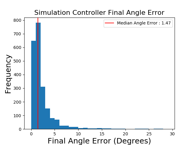
We implement the controller from Section IV-B to reorient an object from start depth image to a desired depth image by using the network trained with the hybrid loss on the full dataset. For all controller experiments, we sample and such that corresponds to a 30° rotation about an arbitrary axis.
Figure 9 visualizes the distribution of the final angle errors achieved by the controller. We find that the controller is able to reorient objects successfully to within a 5° angle error for 90% of trials over 100 random initial orientations for 22 unseen non-symmetric objects. Over these same trials, we obtain a median angle error of 1.47°, suggesting that the controller is able to accurately reorient a variety of objects with different initial/desired orientations.
VI-C Controller Experiments on Physical Objects


We evaluate the proposed method on an ABB YuMi robot with a Photoneo Phoxi camera to reorient a novel object to match the orientation in a target depth image . We place the object inside the gripper of the YuMi and move the gripper into a random orientation for such that the arm and gripper does not significantly occlude the object. We also position the object relative to the camera similarly to the objects positioned in the simulation. As illustrated in Fig. 11, we first take an RGB image from a Logitech camera, depth image from the Photoneo Phoxi camera, and then align the RGB image into the coordinate system of the depth camera. Second, we project the depth image into world coordinates and segment out any pixels that are not within a bounding box around the object. Third, we isolate the object with HSV segmentation. Fourth, we crop and resize the image to 128x128 to generate . We then rotate the object by 30° about and repeat the process to generate . We measure error using ground truth quaternions from the robot’s forward kinematics. We then apply the controller from Section IV to reorient the object back to .
We evaluate the performance of the resulting controller over 10 random initial/desired orientations each for 5 physical objects shown in Figure 10, where each object is tested with 10 random orientations. We use parameters . Figure 12 shows the angle error between the image at iteration () and for these 50 trials. We find that the controller is able to successfully reduce the angle error over iterations, resulting in a final image which is close to the desired image . The controller achieves a median final angle error of 4.2° over these 50 trials. We notice that there is some variance in the controller performance across different start and end orientations for each given object. Thus, estimating the relative orientation between certain start and end images may be more difficult than others due to occlusions from the gripper or fewer overlapping features between the start and end orientations.
VII Discussion and Conclusion
We present an algorithm that uses self-supervised rotation estimation network to orient novel 3D objects. Results suggest that we can orient unseen objects with unknown geometries by an initial error of up to 30° with a median angle error of 1.47° over 100 random initial/desired orientations each for 22 novel objects. We do this by training a deep neural network with a Resnet-9 backbone to predict the 3D rotation between an object in different initial and final orientations and use this network to define a controller to reorient an object with previously unknown geometry. Experiments on physical objects show that the controller can achieve a median angle error of 4.2° over 10 random initial/desired orientations each for 5 physical objects. In future work, we will explore techniques to reduce the rotation prediction error for rotations with larger angles.
VIII Acknowledgments
This research was performed at the AUTOLAB at UC Berkeley in affiliation with the Berkeley AI Research (BAIR) Lab, Berkeley Deep Drive (BDD), the Real-Time Intelligent Secure Execution (RISE) Lab, and the CITRIS "People and Robots" (CPAR) Initiative. Authors were also supported by the Scalable Collaborative Human-Robot Learning (SCHooL) Project, a NSF National Robotics Initiative Award 1734633, and in part by donations from Siemens, Google, Toyota Research Institute, Autodesk, Honda, Intel, Hewlett-Packard and by equipment grants from PhotoNeo and Nvidia. Ashwin Balakrishna is supported by an NSF GRFP. This article solely reflects the opinions and conclusions of its authors and do not reflect the views of the sponsors. We thank our colleagues who provided feedback and suggestions, in particular Mike Danielczuk and Kate Sanders.
References
- [1] Srinivas Akella and Matthew. Mason “Parts Orienting with Shape Uncertainty” In International Conference on Robotics and Automation (ICRA), 1998
- [2] Enric Corona, Kaustav Kundu and Sanja Fidler “Pose estimation for objects with rotational symmetry” In 2018 IEEE/RSJ International Conference on Intelligent Robots and Systems (IROS), 2018, pp. 7215–7222 IEEE
- [3] Michael Danielczuk et al. “Segmenting unknown 3D objects from real depth images using mask R-CNN trained on synthetic data” In 2019 International Conference on Robotics and Automation (ICRA), 2019, pp. 7283–7290 IEEE
- [4] Michael Danielczuk* et al. “Mechanical Search: Multi-Step Retrieval of a Target Object Occluded by Clutter” In International Conference on Robotics and Automation (ICRA), 2019 IEEE
- [5] Michael Dawson-Haggerty “trimesh” In GitHub repository Github, https://github.com/mikedh/trimesh, 2012
- [6] Xinke Deng et al. “Self-supervised 6D Object Pose Estimation for Robot Manipulation” In International Conference on Robotics and Automation (ICRA), 2020
- [7] Thanh-Toan Do, Ming Cai, Trung Pham and Ian. Reid “Deep-6DPose: Recovering 6D Object Pose from a Single RGB Image” In ArXiv abs/1802.10367, 2018
- [8] Kenneth Goldberg “Orienting polygonal parts without sensors” In Algorithmica 10.2-4 Springer, 1993, pp. 201–225
- [9] Frederik Hagelskjær, Thiusius Savarimuthu, Norbert Krüger and Anders Buch “Using spatial constraints for fast set-up of precise pose estimation in an industrial setting” In 2019 IEEE 15th International Conference on Automation Science and Engineering (CASE), 2019, pp. 1308–1314 IEEE
- [10] Kaiming He, Xiangyu Zhang, Shaoqing Ren and Jian Sun “Deep Residual Learning for Image Recognition” In 2016 IEEE Conference on Computer Vision and Pattern Recognition (CVPR), 2016, pp. 770–778
- [11] Tomáš Hodaň et al. “BOP: Benchmark for 6D Object Pose Estimation” In European Conference on Computer Vision (ECCV), 2018
- [12] Diederik Kingma and Max Welling “Auto-encoding variational bayes” In arXiv preprint arXiv:1312.6114, 2013
- [13] Nithyananda Kumbla, Jeremy Marvel and Satyandra Gupta “Enabling Fixtureless Assemblies in Human-Robot Collaborative Workcells by Reducing Uncertainty in the Part Pose Estimate” In 2018 IEEE 14th International Conference on Automation Science and Engineering (CASE), 2018, pp. 1336–1342 IEEE
- [14] Susanna Leveroni and Kenneth Salisbury “Reorienting Objects with a Robot Hand Using Grasp Gaits” In Int. S. Robotics Research (ISRR), 1996
- [15] Yi Li et al. “DeepIM: Deep Iterative Matching for 6D Pose Estimation” In International Journal of Computer Vision 128, 2019, pp. 657–678
- [16] Jeffrey Mahler et al. “Learning ambidextrous robot grasping policies” In Science Robotics 4.26 Science Robotics, 2019, pp. eaau4984
- [17] Iaroslav Melekhov, Juha Ylioinas, Juho Kannala and Esa Rahtu “Relative camera pose estimation using convolutional neural networks” In Advanced Concepts for Intelligent Vision Systems - 18th International Conference, ACIVS 2017, Proceedings Springer Verlag, 2017, pp. 675–687
- [18] D. Morrison, P. Corke and J. Leitner “EGAD! An Evolved Grasping Analysis Dataset for Diversity and Reproducibility in Robotic Manipulation” In IEEE Robotics and Automation Letters 5.3, 2020, pp. 4368–4375
- [19] Keunhong Park, Arsalan Mousavian, Yu Xiang and Dieter Fox “LatentFusion: End-to-End Differentiable Reconstruction and Rendering for Unseen Object Pose Estimation” In arXiv preprint arXiv:1912.00416, 2019
- [20] Valentin Peretroukhin et al. “A Smooth Representation of Belief over SO (3) for Deep Rotation Learning with Uncertainty” In arXiv preprint arXiv:2006.01031, 2020
- [21] Sergey Prokudin, Peter Gehler and Sebastian Nowozin “Deep directional statistics: Pose estimation with uncertainty quantification” In Proceedings of the European Conference on Computer Vision (ECCV), 2018, pp. 534–551
- [22] Ken Shoemake “Animating Rotation with Quaternion Curves” In SIGGRAPH Comput. Graph. 19.3 New York, NY, USA: Association for Computing Machinery, 1985, pp. 245–254
- [23] Stefan Stevic, Sammy Christen and Otmar Hilliges “Learning to Assemble: Estimating 6D Poses for Robotic Object-Object Manipulation” In IEEE Robotics and Automation Letters 5, 2020, pp. 1159–1166
- [24] Supasorn Suwajanakorn, Noah Snavely, Jonathan Tompson and Mohammad Norouzi “Discovery of Latent 3D Keypoints via End-to-end Geometric Reasoning” In Proc. Advances in Neural Information Processing Systems Curran Associates, Inc., 2018, pp. 2059–2070
- [25] Meng Tian, Liang Pan, Marcelo Ang and Gim Lee “Robust 6D Object Pose Estimation by Learning RGB-D Features” In arXiv preprint arXiv:2003.00188, 2020
- [26] Chen Wang et al. “6-PACK: Category-level 6D Pose Tracker with Anchor-Based Keypoints” In International Conference on Robotics and Automation (ICRA), 2020
- [27] Yu Xiang, Tanner Schmidt, Venkatraman Narayanan and Dieter Fox “PoseCNN: A convolutional neural network for 6D object pose estimation in cluttered scenes” In arXiv preprint arXiv:1711.00199, 2017
- [28] Yang Xiao et al. “Pose from Shape: Deep Pose Estimation for Arbitrary 3D Objects” In ArXiv abs/1906.05105, 2019