Task Offloading Optimization in NOMA-Enabled Multi-hop Mobile Edge Computing System Using Conflict Graph Mohammed S. Al-Abiad and Md. Jahangir Hossain are with the School of Engineering, University of British Columbia, Kelowna, BC V1V 1V7, Canada (e-mail: m.saif@alumni.ubc.ca, jahangir.hossain@ubc.ca). Md. Zoheb Hassan is with cole de technologie suprieure (ETS), University of Quebec, Canada (e-mail: md-zoheb.hassan.1@ens.etsmtl.ca).
Abstract
Resource allocation is investigated for offloading computational-intensive tasks in multi-hop mobile edge computing (MEC) system. The envisioned system has both the cooperative access points (AP) with the computing capability and the MEC servers. A user-device (UD) therefore first uploads a computing task to the nearest AP, and the AP can either locally process the received task or offload to MEC server. In order to utilize the radio resource blocks (RRBs) in the APs efficiently, we exploit the non-orthogonal multiple access for offloading the tasks from the UDs to the AP(s). For the considered NOMA-enabled multi-hop MEC computing system, our objective is to minimize both the latency and energy consumption of the system jointly. Towards this goal, a joint optimization problem is formulated by taking the offloading decision of the APs, the scheduling among the UDs, RRBs, and APs, and UDs’ transmit power allocation into account. To solve this problem efficiently, (i) a conflict graph-based approach is devised that solves the scheduling among the UDs, APs, and RRBs, the transmit power control, and the APs’ computation resource allocation jointly, and (ii) a low-complexity pruning graph-based approach is also devised. The efficiency of the proposed graph-based approaches over several benchmark schemes is verified via extensive simulations.
Index Terms:
Conflict graphs, computation offloading, NOMA, resource allocation, admission control, user clustering.I Introduction
The emerging Fifth-Generation (5G) era has brought tremendously increasing computational-intensive and energy-demanding applications, such as 3D modeling and online gaming. However, high computation capability and processing power are required to execute such advanced applications. Today’s smart mobile devices are still resource-constrained in terms of battery and computational capacity. Accordingly, these resource constraints present a key barrier to execute the computational-intensive applications at the mobile devices [1]. Recently, Mobile Edge Computing (MEC) has emerged as an enabling technology to improve computation performance of the 5G era [2]. In an MEC enabled system, powerful MEC servers are placed in close proximity to UDs [3, 4]. Specifically, MEC enables executing the computational-intensive tasks at the network edge servers, thanks to the increased intelligence of the network edge and improved communication performance between mobile devices and network edge servers. This reduces the computation burden and energy consumption of the mobile devices [2, 5].
With the recent progress in fog radio access network, access points (APs) also have certain computation capability [6]. Therefore, MEC can exploit computational capabilities of APs in the network edge and MEC servers. This makes MEC a suitable solution for offloading the computational-intensive and time-sensitive mobile applications. On the one hand, by offloading the computing tasks to adjacent MEC servers [7, 8], the low-latency and high-reliable applications can be executed at the UDs efficiently. On the other hand, the energy consumption of the mobile devices can be improved [9], and consequently, the battery life of smart devices can be prolonged [10]. However, to fully capitalize the advantage of the MEC system, the performance of task offloading from the mobile UDs to MEC servers needs to be optimized. Specifically, the performance of task offloading strongly depends on the data transmission capacity of the links between UDs and MEC servers. Hence, smart resource allocation strategy is imperative for the MEC enabled system, especially in dense networks with large number of UDs and limited radio resource blocks (RRBs) [11].
Non-orthogonal multiple access (NOMA) [12, 13] can improve the spectrum efficiency of a cellular network by increasing the number of scheduled UDs per RRB. Therefore, NOMA is a potential solution to address the challenging problem of supporting the increased number of UDs with the limited number of RRBs in beyond-5G era systems [14]. Specifically, in uplink NOMA, multiple UDs are multiplexed over the same RRB, and the access point (AP) sequentially decodes the UDs’ messages by implementing a successive interference cancellation (SIC) technique [15, 16]. Note that the task offloading from the UDs to the MEC server is an uplink multiple access scheme. Consequently, leveraging the improved spectral efficiency and system capacity, NOMA is also a potential solution to reduce the latency and enhance the energy efficiency of the task offloading process in an MEC system [15, 16]. Accordingly, developing an innovative resource allocation framework is imperative for harnessing the aforementioned benefits of NOMA-based MEC systems.
I-A Related Works and Motivation
Motivated by their numerous potential advantages, MEC and NOMA have attracted extensive studies in their own area [17], [13] and references therein, respectively. Recently, NOMA-based MEC has achieved considerable attention to optimize two main metrics, namely, (i) energy consumption minimization [18, 19, 20, 21, 22, 23, 24, 25] and (ii) delay minimization [11, 15, 26, 27]. The existing works that are separately and jointly optimized these two metrics are explained as follows.
Related works for energy consumption minimization: In [18], [21], the authors optimized the transmit time and power consumption in NOMA-based MEC uplink and downlink systems using geometric programming and successive convex approximation, respectively. In [22], the authors jointly optimized the offloading decision, radio resource allocation, and the SIC decoding to minimize the latency weighted system energy minimization in NOMA-based MEC systems. In [23], the authors jointly considered radio and computation resource allocation and developed a partial task offloading scheme in a NOMA-based MEC heterogeneous network. Particularly, the authors in [23] minimized the energy consumption given a maximum tolerable latency. In [24], the authors investigated joint communication and computation resource allocation in a NOMA-based MEC system while assuming all the UDs offload their tasks to the MEC server. In [25], the authors developed a genetic algorithm based strategy for minimizing the total transmit power in a wireless network.
Related works for delay minimization: Besides minimizing energy consumption, it is also imperative to reduce latency for the delay-sensitive applications. To this end, the following studies investigated resource allocation to minimize latency in NOMA-based MEC system. The authors of [15] minimized the delay of task offloading in a NOMA-enabled MEC system by first transforming the delay-minimization problem into a fractional programming problem, and then developed two iterative solutions. Different form [15], the authors of [26] minimized the maximum task execution latency in a MEC-based NOMA system by optimizing jointly the SIC ordering and computation resource allocation. For improving the efficiency of wireless data transmission, and hence, minimizing the task offloading delay, the authors of [27] exploited NOMA-enabled multi-access MEC by jointly considering the UDs’ offloaded workloads and the NOMA transmission duration. The authors of [11] developed a NOMA-enabled partial computation offloading scheme, where NOMA was employed for both offloading the tasks and downloading the computed results to and from the MEC server, respectively. By designing resource allocations for both uplink and downlink jointly, the authors of [11] minimized the overall delay of completing all the UDs’ tasks.
Related works for joint energy consumption and delay minimization: In the recent literature, a joint optimization of energy and delay metrics was also studied. The authors of [28] minimized the weighted sum of the total delay and energy consumption of all the UDs in a NOMA-enabled fog-cloud computing system. For the same objective, the authors of [29] jointly optimized the computation resource, power and subcarrier allocations, and an iterative algorithm was developed. The authors of [30] systematically investigated the benefits of using NOMA in MEC for both uplink and downlink transmissions and demonstrated that the task processing latency and energy consumption can be minimized by introducing NOMA into MEC systems. Although the aforementioned studies exploited the integration of MEC and NOMA extensively to optimize both latency and energy consumption, the multi-hop MEC architecture with both intelligent APs and MEC servers was not considered in the literature. We emphasize that such a multi-hop MEC architecture is a promising framework to extend the computation service for the cell-edge UDs while exploiting the computation capability of both APs and MEC servers efficiently. Moreover, given the limited number of RRBs compared to number of UDs, NOMA is also promising to improve the number of supported UDs in such a multi-hop MEC architecture. Consequently, in this paper, we study a novel system that integrates the advantages of both multi-hop MEC and NOMA approaches for providing computation services to a large number of UDs.
Motivation: The aforementioned works primarily considered a single-hop scenario where the UDs’ tasks can only be processed at the MEC servers. However, such a single-hop scenario is not efficient for offloading tasks from the cell-edge UDs. In other words, multi-hop scenario needs to be considered for providing reliable computation services to the cell-edge UDs. Motivated by such a requirement, in this work, we investigate NOMA-enabled multi-hop MEC system where the UDs’ tasks can be processed locally at APs or offloaded to MEC servers. Particularly, in the considered system, a set of UDs transmit computational-intensive tasks to a given set of APs where each AP is equipped with number of RRBs. We emphasize that the notion of APs with computation capability is consistent with the recent progress in fog radio access network. Moreover, the architecture of cooperative APs with many RRBs was adopted for maximizing the cloud offloading [31], maximizing the sum-rate [32], and minimizing the delay [33] in both fog and cloud radio access networks. Inspired by [31, 32, 33], this work develops a framework to increase the number of collected tasks from the UDs either for local processing at APs or for offloading them to MEC servers while minimizing both the task processing delay and the energy consumption simultaneously.
Challenges: This paper attempts to solve a joint latency-energy minimization problem in a NOMA-enabled multi-hop MEC system. By applying uplink NOMA protocol over the RRBs, the system can remarkably increase the number of admitted UDs to the APs, and thus, the proposed system is suitable for providing the computation service in a dense network. However, the following challenges need to be addressed. First of all, to take advantage of a NOMA setting for task offloading, the association among the UDs, RRBs, and APs needs to be determined efficiently. Moreover, NOMA inevitably introduces interference in the system, and thus, the transmit power of the UDs needs to be optimized to further improve the transmission rate and reduce latency of task offloading process. Finally, the APs usually do not have enough computing resources and may not meet large-scale UDs’ tasks. Thus, the APs need to smartly offload large-scale UDs’ tasks to adjacent MEC servers. Nevertheless, the multi-hop communication can introduce additional latency. Essentially, the computation resources of both the MEC servers and the APs need to be managed appropriately to take advantage of both the local and centralized computation services. It is therefore evident that the NOMA-enabled multi-hop MEC system has several degrees-of-freedom, namely, the UD-AP-RRB association, UD power optimization, local computations at the APs, and task offloading at the MEC servers. A joint optimization of the aforementioned degrees-of-freedom is presented. To the best of the authors’ knowledge, this is the first attempt in the literature to optimize jointly the degrees-of-freedom of a NOMA-enabled multi-hop MEC system.
I-B Contributions
In this paper, we consider incorporating multi-hop task processing into the conventional MEC-NOMA system. In the envisioned system, the APs have multiple RRBs that collect tasks for local processing at the APs or for offloading to MEC servers. To this end, we introduce innovative graph-theoretical frameworks by taking the UD-AP-RRB scheduling, UD power optimization, local computation resource allocation, admission control and offloading decisions into account. The main contributions of our work are presented as follows.
- 1.
For a NOMA-enabled multi-hop MEC system, we develop a framework where APs and MEC servers collaborate to minimize the delay of processing tasks and energy consumption jointly. To this end, a weighted-sum method of latency-energy consumption minimization problem is formulated with the constraints on UD-AP-RRB scheduling, maximum local computation resource allocation, UD transmission power, and maximum tolerable delay guarantee. Such an optimization problem is NP-hard and computationally intractable. To obtain a tractable solution, we decompose the original problem into two sub-problems, and obtain efficient solutions to both sub-problems. The first subproblem obtains scheduling among UDs, RRBs, and APs, UDs’ transmit power control, and local computation resource allocation. The second sub-problem obtains the decisions of offloading the collected tasks from the APs to MEC server(s).
- 2.
To solve the first sub-problem, we design a joint MEC (J-MEC) graph that optimally solves the UD-AP-RRB scheduling and power allocation problem, jointly, and we propose a closed-form solution for the local computation resource allocation for the given UD-AP-RRB scheduling. To solve the second sub-problem, we propose a cross-layer weighting solution based on the optimized resource allocation variables of the first sub-problem. The aforementioned graph-based and cross-layer weighting solutions of the corresponding sub-problems is referred to a Joint Approach.
- 3.
Since the joint approach requires generating all the possible NOMA clusters (i.e., combinations between UDs), it exhibits high computational complexity. Therefore, we develop a low-complexity graph pruning algorithm that judiciously generates NOMA clusters that are feasible for tasks local processing. Using these generated NOMA feasible clusters, our proposed algorithm designs a new reduced NOMA graph. Thereafter, by applying a greedy maximum-weight-independent set (MWIS) algorithm, we obtain a feasible solution to the reduced NOMA graph.
- 4.
Numerical results reveal that the proposed schemes offer improved latency and energy consumption as compared to the baseline schemes. Moreover, our proposed pruning graph approach reduces the computational complexity significantly with small performance loss compared to the joint approach.
The rest of this paper is organized as follows. The system model is described in Section II. We formulae and transform the weighted-sum latency-energy consumption optimization problem in Section III. In Section IV and Section V, we develop a joint approach and a low-complexity graph pruning solution to find the optimized scheduling decision, respectively. Simulation results are presented in Section VI, and in Section VII, we conclude the paper.
II System Model
II-A System Overview
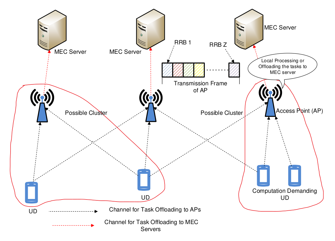
We consider the NOMA-enabled and multi-hop MEC system illustrated in Fig. 1 with MEC servers, access points (APs), and computation demanding user devices (UDs). The sets of MEC servers, APs, and UDs are denoted by , , and , respectively. MEC servers and APs are equipped with CPUs that help computing the tasks, and accordingly, they cooperate with each other to execute the demanding computationally-intensive tasks of UDs. The MEC servers possess stronger task processing capabilities, while the APs have certain computation resources [6], [34]. We consider that each AP has a limited coverage range, denoted by , which represents the service area of the -th AP within a circle of radius . The service area of each AP is a set of UDs which defined by }, where is the distance between the -th AP and the -th UD. Let be the AP allocation matrix, where element represents that the -th UD is allocated to the -th AP, and otherwise.
Similar to [31, 32], we consider that each AP has orthogonal radio resource block (RRBs) that are denoted by the set , where UDs can transmit their demanding tasks to the APs for local processing or for offloading to MEC servers via APs. Thus, the total number of RRBs in the system is . Let be the RRB allocation matrix, where element represents that the -th UD is allocated to the -th RRB in the -th AP, and otherwise. We assume each UD can be allocated with only one RRB, and to schedule number of UDs to each RRB, we consider NOMA. To manage co-channel interference caused by NOMA, the APs utilize SIC technique to decode the multiple overlapping signals sequentially, where the decoding order is descending in terms of channel power gain. For reducing the complexity of SIC-based decoding, we consider that each RRB can only serve at most UDs. Consequently, the number of admitted UDs for task processing is at most , and the rest local-infeasible and not-admitted UDs will fail in task processing. We denote that the 2-UDs association in each RRB by a NOMA cluster.
On the UD side, we consider that each UD has only one inseparable computation task, which can be represented by , where is the size of input data (in bits), is the processing density (in CPU cycles/bit), and is the maximum tolerable latency (in second) within which the task should be completed successfully. The input data of the -th UD with a size of should be locally processed at the potential AP or transferred to the MEC server in task offloading mode [35, 36]. Since tasks have different sizes, they need an efficient computational processing strategy such that they can be processed within their maximum tolerable latency.
For UD-AP uplink transmission strategy, tasks are transmitted over different RRBs via a wireless link. Let and denote the transmission power of the -th UD and the -th AP, respectively. Let be a matrix containing the power levels of all UDs, i.e., . To avoid complexity, we consider fixed transmission power for the APs. The instantaneous signal-to-interference-plus-noise (SINR) for the link between the -th UD and the -th RRB in the -the AP is given by
| (1) |
where denotes the additive white Gaussian noise variance and denotes the channel fading gain for the link between the -th UD and the -th RRB in the -th AP. Then, the transmit rate of the -th UD on the -th RRB in the -th AP can be given by , where is the bandwidth of the -th RRB. Consequently, the transmit rate of UD can be given by
| (2) |
At the APs, UDs’ collected tasks can be either processed locally or offloaded to MEC servers. Therefore, APs offload UDs’ tasks (if not processed locally) to MEC servers via multiple orthogonal channels. So, the transmission rate of the -th AP to offload the collected data to the -th MEC server is where denotes the channel gain from the -th AP to the -th MEC server.
II-B Local Processing and Task Offloading
1) Local processing: Let be the computational speed of the CPU in the -th AP (in cycles per second). Let be a matrix containing the local computations of all APs, i.e., . The uplink transmission delay for sending the -th task to the -th RRB in the -th AP is . Let denote the set of collected tasks at the -th AP across all the RRBs. Then, the delay (i.e., uploading transmission delay and task processing delay) and energy consumption of in local processing mode can be given by and , respectively, where is a constant coefficient about the CPU chip architecture [37]. Simply, if AP has only one RRB and can only collect one task, the delay and energy consumption of task of UD in local processing mode can be simply expressed by and , respectively.
2) Task offloading: If tasks are going to be processed at the MEC servers, APs need to transfer the collected data to the MEC servers. Let denote the offloading decision of each AP , where indicates that the collected tasks is offloaded, and otherwise. We define the offloading decision such that:
| (3) |
Based on the offloading decision , the uplink transmission delay for sending the collected tasks from the -th AP to the -th MEC server is . Let be the computational speed of the CPU in the -th MEC server (in cycles per second). For analytical tractability, we consider that MEC server will start to process only when it has successfully received all the corresponding data from the -th AP. Suppose that MEC server can allocate the collected tasks with sufficient computation resource for task processing, then the delay and energy consumption of tasks in task offloading model can be given by
| (4) |
| (5) |
where is the idle power of the -th AP. In (4), the first term represents the transmission duration for sending from UDs to the -th AP, the second term represents the transmission duration for sending from the -th AP to the -th MEC server, and the third term is for task processing at the -th MEC server.
3) Offloading scheme: The collected tasks of the UDs can be computed locally at the APs or simultaneously offloaded to the MEC servers from the APs via orthogonal channels. The scheduling problem of this offloading scheme consists of assigning tasks to APs or MEC servers under the following constraints:
- •
Each UD is assigned to only one RRB and one AP, while each RRB can schedule at most two UDs using NOMA.
- •
The collected tasks can be locally processed at one AP or offloaded to only one MEC server based on the offloading decision .
4) Admission control and energy consumption: Since the number of MEC servers is less than that of APs, at most APs can be admitted in for tasks offloading. Let be the admission control variable, where denotes that the collected tasks at the -th AP is permitted to access the MEC servers, and otherwise. By considering offloading decision and admission control, the delay and energy consumption of tasks is given by
| (6) |
| (7) |
Consequently, the latency of processing tasks can be expressed as
| (8) |
where is the computational processing delay of tasks given the offloading schedule , and accordingly, the total latency is given by
| (9) |
Finally, the overall energy consumption for locally processing the tasks at the APs or offloading them to the MEC servers based on the offloading decision is expressed as . The main symbols used throughout this paper are listed in Table I.
| Symbol | Definition |
|---|---|
| Sets of UDs, APs, MEC servers, RRBs | |
| Computational speed of MEC server (in cycles per second) | |
| Computational speed of AP (in cycles per second) | |
| Size of task in (bits) | |
| Transmission powers of UD and AP | |
| Offloading decision | |
| Processing density of the task of UD (in CPU cycles/bit) | |
| Maximum tolerable latency of each task (in second) | |
| , | Delay and energy consumption of locally processing tasks |
| , | Delay and energy consumption of offloading tasks |
| Set of UDs in the coverage area of AP | |
| Matrix of RRB allocation | |
| Uplink data rate of UD on RRB in AP (in bits/second) | |
| Uplink data rate of AP to MEC server (in bits/second) | |
| Uplink delay of sending task to RRB in AP (in second) | |
| Set of collected tasks by AP | |
| UD-AP allocation matrix | |
| Latency of completing all the tasks | |
| Latency of completing tasks (in second) | |
| Overall energy consumption |
III Problem Formulation and Transformation
III-A Problem Formulation
We propose to minimize the completion of processing demanding tasks as well as the energy consumption, and formulate the problem as the joint optimization of offloading decision , RRB assignment , UD-AP association , and computational resource allocation. To tackle the trade-off between latency and energy consumption, we consider the weighted sum method, in which the latency-energy consumption cost function of the scheduling and offloading scheme can be formulated as follows . Here, and are the predefined weight factors.
Let the binary variable (where and ) be if AP is scheduled to MEC server , and otherwise. Consequently, the optimization problem is formulated as at the top of the next page.
In , C1 states that each task should be accomplished within a tolerable deadline; C2 indicates that each UD is scheduled to only one AP and allocated with only one RRB; C3 indicates that maximum two UDs can be scheduled to each RRB at the same time; C4 states that each AP is scheduled to only one MEC server; C5 is the constraint on local computation resource allocation; C6 and C7 are the constraints on transmit power control and rate threshold , respectively.
III-B Problem Transformation
Solving problem owing to its mixed combinatorial characteristics and objective-constraints coupling is challenging [38, 39]. Hence, it is crucial to propose an effective approach that is affordable for the large-scale situations of . To this end, we reformulate into two sub-problems, namely, (i) AP side optimization problem that optimizes UD-RRB-AP scheduling, power control, and local computation allocation, and (ii) MEC server side optimization problem that jointly optimizes admission control and offloading decisions. Next, we solve the reformulated sub-problems separately. For the tractability of ensuing the analysis of problem reformulation, we have the following remarks.
Remark 1: In order to maximize the effective system capacity that represents the number of UDs whose tasks are processed successfully, we encourage as many UDs to upload their tasks to RRBs and employ NOMA in each RRB.
Remark 2: In order to minimize the uplink transmission delay from UDs to APs, we judiciously select a significant set of UDs whose data rates to the RRBs/APs are good, and in each RRB we employ power allocation.
Distributed Local Computation Optimization: Each AP first assumes that its collected tasks are processed locally, i.e., the offloading decision , and then solves the problem , given at the top of the next page, to obtain the UD-RRB-AP scheduling, power optimization, and local resource allocation strategies.
| (11a) | ||||
In , the optimization is over the continuous variables , , and the discrete variables , and . The multi-variable problem can be decomposed into the following sub-problems.
- •
UD Scheduling and Power Allocation Problem: For a fixed set of local computation allocation , the optimization problem can be written as
(12a) The problem is a mixed-integer non-linear programming problem, and its suitable solution is obtained by applying the graph theory.
- •
Local Computation Resource Allocation Problem: For a fixed UD scheduling and power allocation, the problem is independently written per AP as
(13a) Since is independent in the objective and constraints, the optimization in each AP is independent from each other, and thus the constraints C1 and C4 in can be re-written as . Consequently, can be farther transferred to the following optimization problem.
(14a) Remark 1: Our local-related optimization has low computational complexity, since the solution to local computation resource allocation can be obtained in closed form as given in the next section.
MEC Server Offloading Optimization: After obtaining , UD-RRB-AP scheduling, and power control , problem reduces to
| (15a) | ||||
More precisely, this optimization considers admission control and offloading decisions for MEC servers. In the next two sections, we present efficient methods to solve the optimization problems and using conflict graph models.
IV A Graph Theory-based Solution: Joint Approach
In this section, we develop an efficient joint solution to the optimization problem and using techniques inherited from graph theory. To this end, we first design a joint MEC graph, denoted by J-MEC graph, that represents all feasible UD and power allocation schedules. As such, can be solved jointly. Given the solution of , we then develop admission control and offloading decision algorithm for solving .
IV-A J-MEC Graph Design and Power Optimization
1) J-MEC graph description: Let denote the set of all possible combinations between UDs, APs, and RRBs, i.e., , and is a NOMA association which is an element in , i.e., . For convenience, represents the -th UD in association . The weighted undirected J-MEC graph is denoted by where stands for the set of all the vertices, is the set of all the edges, and denotes the set of vertex weights. The designed J-MEC graph graph considers all the conflict transmissions between UDs across all RRBs in all APs. A vertex in this graph is generated for each association in , i.e., and . Two distinct vertices representing and representing are adjacent by a scheduling conflict edge if one of the following cases occurs:
- •
CC1: The same UDs (any UD or both UDs) are associated with both vertices and .
- •
CC2: The same RRB in the same AP (or different APs) is associated with both vertices and .
Mathematically, two distinct vertices representing and representing are connecting by a conflict edge if and only if .
To select the UD-RRB-AP scheduling that provides a local minimum delay and guarantees minimum energy consumption, we assign a weight to each vertex . For notation simplicity, we define the utility of UD as . Therefore, the weight of vertex that reflects both the minimum delay and energy consumption can be given by
| (16) |
where and are the utility of two UDs and , respectively. The weight of vertex in (16) is determined by the transmit powers , , RRB , and AP allocated to them.
Using , the optimization problem for a fixed is similar to
minimum-weight independent set (MWIS) problems in several aspects. In MWIS problems, two vertices must be nonadjacent in the graph, and similarly, in problem , two NOMA clusters cannot be allocated with the same RRB or contain
at least one UD. Moreover, the objective of problem is to minimize the delay and energy consumption, and similarly, the
goal of MWIS is to minimize the weight of all vertices. Consequently, we have the following theorem.
Theorem
Using , problem for fixed can be equivalently transformed to the problem of determining the MWIS.
Proof.
Let , be the MWIS that is associated with the feasible schedule . Let is the set of all possible independent sets in . For each vertex that is associated with association of UD, power, rate, RRB, and AP, the weight in (16) is the minimum local computation delay and energy consumption that the induced NOMA cluster in vertex receives, i.e., the utility under the optimal transmit power of UDs. Therefore, the weight of the MWIS is precisely the objective function of problem and can be written as . Since each vertex is a feasible NOMA cluster, i.e., same UDs are scheduled to different RRBs, constraints (C2) and (C3) hold. ∎
2) Power control optimization: A proper power allocation for each UD leads to suppress the interference in NOMA clusters, thus a better uplink transmission rate is achieved. As a result, the uplink transmission duration for delivering tasks to RRBs/APs is minimized. Consider a NOMA-cluster in that is associated with a feasible scheduling . Our goal is to obtain a local optimal UD power allocation vector, denoted as () for that NOMA-cluster. The power allocation problem is formulated as an optimization problem of maximizing the weighed sum-rate. As such, all the scheduled UDs transmit their tasks to the associated RRBs/APs with minimum uplink transmission duration, which can be expressed as follows
| (17a) | ||||
where the optimization is over the power levels .
IV-B MEC Tasks Offloading
After obtaining the UD scheduling and of all APs in the network, by solving , now we are ready to solve for tasks offloading. As mentioned before, the number of APs is higher than the number of MEC servers, thus there can be at most collected tasks admitted in and served by the MEC servers. Accordingly, we need to perform admission control, to pick out the number of collected tasks . Intuitively, APs in good channel conditions will benefit from task offloading, since the data transmission rate will be high, and consequently low delay in data offloading transmission. Moreover, the characteristics of tasks can play important roles. In the one hand, tasks with high sizes are most likely not suitable for offloading as the energy consumed in uplink transmission may be higher than the energy consumed in task processing. On the other hand, tasks with high processing density can be beneficial in task offloading to MEC servers as less energy will be consumed in task processing.
Inspired by the aforementioned observations, we propose a cross-layer weighting solution for admission control that are explained as follows. For each AP, we define the first-layer weight as follows
| (18) |
In (18), represents both the latency and consumption energy if collected tasks has been processed locally, given the solution to . Now, let us define the second-layer weight as follows
| (19) |
where indicates the transmission data rate from the -th AP to the -th MEC server. Particularly, a larger primary value of offers a smaller uplink time from the AP of each represented task . The larger is, the more likely it is for the -th AP to perform task offloading. Based on this, we propose low complexity algorithm that captures admission control among the local-infeasible AP. We first sort in a decreasing order and select the first APs to perform task offloading based on the maximum , and the rest will do local processing.
IV-C Greedy Algorithm
The optimization problem is a mixed-integer non-linear programming problem. The global solution is, therefore, equivalent to a minimum-wight independent set over J-MEC graph, which is NP-hard problem [41], and so is the problem . However, such problem can be near optimally solved with a reduced complexity as compared the naive exhaustive search methods, e.g., the algorithm in [42]. The MWIS can be solved efficiently as explained in this subsection. While the proposed solution is not necessarily optimum, it works very-well for solving .
The joint local computation resource allocation and offloading decision optimization algorithm is broken into two phases as follows.
Phase I: In this phase, we solve the local computation resource allocation problem in two stages (i) designing the J-MEC graph and the minimum weighted vertex search algorithm and (ii) finding the local computations of APs. This phase is explained as follows.
Stage 1: First, the J-MEC graph can be designed as follows. We generate all the possible schedules of UD-NOMA clusters, RRBs, and APs. Afterwards, for each feasible schedule , a vertex is generated. The optimal power levels of each association are calculated by solving the optimization problem . The vertex in is created by appending the computed power levels and the corresponding rates to that vertex. We repeat the same steps above for all vertices. The J-MEC graph is, then, constructed by adding connections according to CC1 and CC2.
Second, the algorithm itratively and greedily selects the MWIS among all the maximal independent sets in the J-MEC graph, where in each iteration we implement the following procedures. The algorithm computes the weight of all generated vertices using (16). The vertex with the minimum weight is selected among all other corresponding vertices. The selected vertex is, then, added to , where is initially empty. Afterwards, we update the graph by removing the selected vertices and its connected vertices. As such, the next selected vertex is not in conflict connection with the already selected vertices in . The process continues until no more vertices exist in J-MEC graph . Since each RRB in each AP contributes by a single vertex, the number of vertices in is .
Stage 2: Given the UD scheduling and power allocation of the APs from stage 1, we now find the local computation resources of the APs as follows. We first calculate the local computations of the collected tasks in each RRB for all APs. Then, similar to [40], we repetitively perform the following three closed-form procedures.
- 1.
If , the local processing of tasks is feasible, and most likely these collected tasks will be processed at AP . Thus, we set and .
- 2.
If , the local processing is feasible, and most likely will be processed at AP . Thus, we set and .
- 3.
If , local processing is infeasible, and most likely will be offloaded. Thus, we set . Such collected tasks will not be considered for the next iteration of performing stage 1.
The above two-stages process is repeated until a maximum number of iterations is reached.
Phase II: In the second phase, we solve the admission control and offloading decision optimization problem . Particularly, this phase characterizes the solution of by allocating the collected tasks of APs to the MEC-servers, such that the delay and energy consumption of tasks offloading is minimized. We first calculate and (), and then we sort the collected tasks in a descending order according to . The index of the sorted collected tasks is . The collected tasks with has the higher priority to be associated with the best available MEC server. Each iteration is implemented as follows. We label the AP that has the maximum value of and find its corresponding second-layer weight that has the maximum value among all other corresponding AP-MEC server associations. The selected AP-MEC server association is, then, added to , where is initially empty. Afterwards, we update the list of values and by removing the selected AP and its associated , set , and set . The algorithm, then, locates the second maximum-value and find its corresponding AP-MEC server association that has the highest secondary value . The process continues until no more available MEC servers in the network, and the remaining APs will perform local processing computations. The process of phase II is presented in Algorithm 1.
The overall two-phase algorithm to the problem and problem is summarized in Algorithm 2.
IV-D Complexity Analysis
1) Complexity of Algorithm 1: The computational complexity of sorting all the APs in Step 8 of Algorithm 1 is . Meanwhile, the required complexity of associating an AP with an MEC server is , and the computational complexity for executing Steps 9-17 of Algorithm 1 is . Hence, the total computational complexity of Algorithm 1 is .
1) Complexity of Algorithm 2: The computational complexity of generating all NOMA clusters representing all vertices in the J-MEC graph is . Then, connecting all these vertices requires a complexity of 2. Therefore, the overall computational complexity is 2. Such high complexity is due to generating all the possible NOMA clusters which increases significantly as the number of UDs in the network increases.
V A Graph Theory-based Solution: Pruning Graph Approach
In the previous section, we solved jointly for UD scheduling, power control , and local computation . This requires high computational complexity for building J-MEC graph and solving the power control optimization for each vertex. To tackle such high complexity, we recommend to solve for fixed . In particular, our proposed innovative method in this section introduces a sequential pruning graph algorithm that judiciously generates NOMA clusters whose tasks are certainly can be processed locally at the APs while simultaneously designing a reduced J-MEC graph. In the reduced J-MEC graph, we do not need to generate all the possible NOMA clusters in the network which significantly reduces its size.
Towards that goal, this section first addresses the optimization problem as a UD scheduling, power control, and offloading decision optimization problem, and can be written as
| (20a) | ||||
To solve the problem in , we develop a simple approach that first solves the UD scheduling and power optimization problem using the pruning graph method and then solves the admission control and offloading decisions as in Algorithm 1.
V-A Low Complexity Graph Pruning Solution
In this subsection, we propose a low complexity, yet suboptimal, solution for solving the UD scheduling and power control problem part in . Particularly, we first check the condition for generating feasible vertices that their associated tasks can be processed locally. Based on this, we propose a method for generating only such NOMA clusters while simultaneously constructing the reduced J-MEC graph.
1) Graph description: Let represents the reduced J-MEC graph. To design , we itertaively generate a vertex for each UD (UDs), RRB, and AP in the network as follows. We start from RRB , and assume that UD is allocated to it. Then we calculate the local task processing computation of and check the possible three scenarios:
- 1.
If UD is infeasible for a local processing at the -th RRB in the -th AP, we suppose UD is associated with RRB , and then continue to calculate and judge the feasibility.
- 2.
If UD is feasible for a local processing at the -th RRB in the -th AP and , then we find the second UD (currently, ), for the () pair. Afterwords, calculate the transmitting powers and and generate a vertex that represents a NOMA cluster. We then compute the weight of that vertex and update the graph . If adding is infeasible, we let , and we verify the feasibility and repeat the aforementioned step.
- 3.
If UD is feasible for a local processing at the -th RRB and , then we allocate this UD to RRB , calculate the transmitting power , and generate a vertex that represents only one UD. We then compute the weight of that vertex and update the graph .
By iteratively repeating the above process (1)-(3) for all , , we can obtain all the feasible vertices . To obtain all the feasible NOMA clusters, we repeat the above process for each . The vertices in the resulting constructed are connected using CC1 and CC2 in section V.
2) Updated MWIS search method: Since our proposed solution here greedily selects a number of UDs that can transmit their tasks to the RRBs/APs while minimizing the delay and energy consumption, we need to maximize the number of vertices that have minimum weights. In order to do that, the weight of each vertex needs to be updated. An appropriate design of the updated weights of vertices leads to selection of a large number of vertices and each vertex has minimum original weight that is defined in (16). Such updated MWIS method was adopted in [31] and [33] to efficiently offload cloud and minimize delay, respectively.
Let define the non-adjacency indicator of vertices and in the graph such that:
| (21) |
Next, let denotes the weighted degree of vertex , which can be defined by , where is the original weight of vertex defined in (16). Hence, the modified weight of vertex is defined as
| (22) |
In (22), the weight of a vertex has two features: (i) it has a minimum original weight and (ii) it is not connected to a large number of vertices that have minimum original weights. Based on this, we iteratively and heuristically execute a greedy vertex search scheme as follows. Initially, we pick up a vertex that has the minimum weight and add it to the maximal IS (i.e., ). Then, the subgraph , which consists of vertices in graph that are not connected to vertex , is extracted and considered for the next selection. In the next step, a new minimum weight vertex is selected from subgraph (at this point ). We repeat this process until no further vertex is not connected to all the vertices in . This approach is presented in Algorithm 3.
Remark 4: Notably, the graph contains only feasible clusters, and thus it is a sub-graph of the J-MEC graph constructed in section V. Therefore, the designed graph generated by Algorithm 3 provides the near-optimal solution to .
V-B Complexity Analysis
The computational complexity of Algorithm 3 is dominated by the required complexity of generating feasible NOMA clusters (i.e., vertices in the reduced J-MEC graph), and connecting the generated vertices. To generate the feasible NOMA clusters by executing Steps 4-24 of Algorithm 3, the required computational complexity is . Meanwhile, the required complexity of connecting the generated vertices by executing Step 25 of Algorithm 3 is . Therefore, the overall computational complexity of Algorithm 3 is . Essentially, for a dense network with large number of UDs, Algorithm 3 requires significantly reduced computational complexity than the joint approach of Algorithm 2.
VI Numerical Results
VI-A Simulation Setting and Comparison Schemes
We consider a NOMA-enabled and multi-hop MEC system where APs and MEC servers have fixed locations and UDs are distributed randomly within a hexagonal cell of radius m. Unless otherwise stated, we set the numbers of APs and MEC servers to , , respectively. In addition, each UD has one task to be processed locally at APs or at MEC servers. The channel model follows the standard path-loss model, which consists of three components: 1) path-loss of for UD-RRB/AP transmissions and path-loss of for AP-MEC server transmissions; 2) log-normal shadowing with dB standard deviation; and 3) Rayleigh channel fading with zero-mean and unit variance. The noise power and the maximum’ F-AP and user power are assumed to be dBm/Hz and dBm/Hz, respectively. The link bandwidth is MHz. Other parameters are summarized in Table II. To assess the performance of our proposed joint and pruning graph approaches, we simulate various scenarios with different number of UDs , input data , number of RRBs , and processing density . For the sake of comparison, our proposed schemes are compared with the following baseline schemes.
- •
Local: In this scheme, all APs process the collected tasks locally, and local resource allocation optimization is performed. When AP local processing is not feasible, unsuccessful task processing happens.
- •
All-offload: In this scheme, the APs offload their collected tasks to the MEC servers, and no local processing at the APs. When MEC server side processing is not feasible, unsuccessful task processing happens.
- •
Random-offload: In this scheme, resource allocation and tasks offloading decisions are made randomly, and other optimization is performed. For resource allocation, we pick up a random MWIS in the J-MEC graph.
Also, we adopt three performance metrics as follows: (i) the latency-energy consumption cost function that represents the objective in for the proposed joint scheme and for the proposed pruning graph scheme, (ii) the effective system capacity that represents the total number of UDs whose tasks are successfully processed, and (iii) the latency that was shown in (9).
| Parameter | Value |
|---|---|
| Cell radius | m |
| Circle radius of AP’s service area | m |
| Cluster radius | Mbits/s |
| Input data size, | Kbit |
| Processing density, | |
| MEC server capability, | G cycles/s |
| Local capability constraint, | G cycles/s |
| Maximum tolerable latency, | ms |
| CPU architecture based parameter, |
We first plot in Fig. 3 the latency-energy consumption cost function versus the number of UDs . From this figure, it can be seen that our proposed schemes offer an improved performance in terms of cost function as compared to the other schemes. This improved performance is due to the joint and pruning graph schemes that (i) judiciously schedule UDs to APs/RRBs, adopt the transmission rate of each UD and optimize the transmission power of each UD, and (ii) smartly offload heavy intensive tasks that cannot be locally processed at APs to the potential MEC servers. Particularly, the random scheme suffers from randomly picking up a random MWIS that could have weak transmission rates from UDs and APs. As a result, a higher tasks uploading transmission, and it leads to a high latency. Further, the random selection of AP associations to MEC servers degrades its cost function performance. The local scheme focuses on processing the tasks locally at the APs, which degrades its cost function performance since APs have low processing capability. Thus, it consumes more energy and needs high latency for processing UDs’ demanding tasks. On the other hand, in all-offload scheme where the collected tasks at the APs are offloaded, MEC servers have high processing capability, and accordingly, they can process the offloaded tasks quickly. This results in an improved performance as compared to all schemes, including our proposed pruning graph scheme. Notably, since all-offload scheme can only benefit UDs, the cost function nearly sightly changes when is greater than . Our proposed joint scheme fully leverages the whole dimension of the J-MEC graph that considers a joint optimization of UDs scheduling, power control, and low processing optimization, and offloading decisions. Consequently, a close performance of our proposed joint scheme and all-offload scheme is achieved. This is because both local-related and MEC server-related optimizations come into full play. Moreover, since the joint scheme considers all NOMA clusters, it works better than our proposed graph pruning scheme.
In Fig. 3, we plot the effective system capacity versus the total number of UDs . When increases form to , the total number of RRBs across all APs is relatively sufficient (), so the system capacity grows relatively fast. The system capacity reachs supported UDs when for the proposed schemes. When is nearly , the effective system capacity of our proposed schemes stop growing and can have at most supported UDs. Although the all-offload scheme has an improved cost function performance as in Fig. 3, it severely degrades the effective system capacity performance because it can serve at most UDs (i.e., ). This makes the all-offload scheme impractical for dense NOMA-enabled and multi-hop MEC systems. The random scheme degrades the effective system capacity performance due to the random selection of MWIS in the reduced-NOMA graph, which results in a few number of vertices representing NOMA clusters. In contrast, our proposed schemes greedily select many vertices that have minimum weights and not adjacent to many vertices that have minimum weights. This shows the improved performance of our proposed schemes in Figs. 3 and 3 as compared to the random scheme.
In Fig. 5, we show the latency of processing UDs’ tasks versus the number of UDs for an input data of Kbit. Again, for the above-mentioned reasons in Figs. 3 and 3, our proposed schemes outperform other schemes. It can be observed from Fig. 5 that increasing the number of UDs leads to an increased latency of all schemes. This is because when the number of UDs increases, the number of collected tasks for local processing or for offloading increases, thus leads to an increased in the maximum latency for uploading the tasks across all RRBs. To illustrate the impact of increasing the input data size on the latency, we plot in Fig. 5 the latency against the number of UDs for different ranges of of and Kbit. Fig. 5 shows the size of input data and how long it takes for the proposed solutions to upload and processed such data at APs and MEC servers. We can observe that the latency performances of all schemes increase with the data size. This is in accordance with the latency expression in (9), where it was emphasized that increases with . As increases, more bits are needed for uploading. Thus, time delay is increased to receive data from UDs.
In Figs. 7 and 7, we plot the latency-energy consumption cost function and the effective system capacity versus the number of RRBs , respectively. As can be seen, the number of UDs that MEC servers and APs can afford increases linearly with . In all-offload method, because UDs can offload their tasks based on the number of MEC servers of , the cost function grows slowly and the effective system capacity of the supported UDs keeps unchanged at . Again, the all-offload scheme is not practical in terms of the effective system capacity, thus it serves in this work as a benchmark scheme. All other schemes, including our proposed, random, and local, follow the same rules, i.e., at first their effective system capacity grow fast, and then gradually slow the number of RRBs. Meanwhile, it can also be found that the cost function and effective system capacity performances of our proposed algorithms always outperform the random and local methods.
In Figs. 9 and 9, we plot the latency-energy consumption cost function and the effective system capacity versus the processing density , respectively, under default system size parameters, i.e., , , and in the range of Kbit. When falls among a small numerical interval , where the task is very simple and local processing is feasible and suitable, almost all the tasks will be processed locally with success. However, this slightly increases the cost function of the local scheme as the uploading transmission of such increased number of tasks is increasing. Except for all-offload scheme, the effective system capacity of other algorithms all reach the maximum value of supported UDs and have the almost similar cost function performance. For random scheme, since UDs and tasks are randomly scheduled to UDs and offloaded to MEC servers, respectively, resulting in poor cost function performance and smaller effective system capacity, as shown in Figs. 9 and 9. When grows to , the performance of local scheme deteriorates rapidly, so the number of local feasible UDs declines rapidly, i.e., when , the cost function of the local scheme is almost zero since no tasks of UDs can be locally processed at the APs. For our proposed schemes, due to multiple-dimensional joint optimization, the cost function slightly increases. In terms of effective system capacity, since the number of local feasible UDs drops greatly, and MEC servers can only accommodate UDs for task offloading, the effective capacity of all other algorithms reduce rapidly, except for all-offload scheme, as shown in Fig. 9. Since the processing density has a negligible effect on MEC server execution as in the all-offload scheme, the cost function slightly changes based on the latency of uploading tasks and the effective system capacity remains unchanged.
VII Conclusion
In this paper, we investigated the joint optimization of latency and energy consumption in the NOMA-enabled and multi-hop MEC system in which the APs are equipped with local processing functionalities. By using the graph theory technique, we proposed two different approaches, namely, the J-MEC graph and the pruning graph approaches to obtain efficient solutions to the joint latency-energy optimization problem. The presented numerical results revealed that both proposed schemes achieve significant gains in terms of the latency and energy consumption minimization compared to the baseline solutions. Compared to the proposed J-MEC graph approach, the pruning graph approach has some degradation in the system performance. However, this small performance degradation is obtained by reducing the computational complexity significantly compared to the joint approach. Therefore, our proposed graph-based approaches offer a suitable trade-off between the performance and the computational complexity.
References
- [1] A. Kiani and N. Ansari, “Edge computing aware NOMA for 5G networks,” IEEE Int. of Things Jou., vol. 5, no. 2, pp. 1299–1306, Apr. 2018.
- [2] S. Barbarossa, S. Sardellitti, and P. D. Lorenzo, “Communicating while computing: Distributed mobile cloud computing over 5G heterogeneous networks,” IEEE Signal Process. Mag., vol. 31, no. 6, pp. 45–55, Nov. 2014.
- [3] P. Mach and Z. Becvar, “Mobile edge computing: A survey on architecture and computation offloading,” IEEE Commun. Surv. Tut., vol. 19, no. 3, pp. 1628–1656, Jul.–Sep. 2017.
- [4] A. A. Al-habob and O. A. Dobre, “Mobile edge computing and artificial intelligence: A mutually-beneficial relationship,” IEEE ComSoc Tech. Committees Newslett., Apr. 2020, arXiv:2005.03100.
- [5] N. Abbas, Y. Zhang, A. Taherkordi, and T. Skeie, “Mobile edge computing: A survey,” IEEE Int. of Things Jou., vol. 5, no. 1, pp. 450-465, Feb. 2018.
- [6] Q. Li, H. Niu, A. Papathanassiou, and G. Wu, “Edge cloud and underlay networks: Empowering 5G cell-less wireless architecture,” in Proc. 20th Eur. Wireless Conf., May 2014, pp. 1–6.
- [7] X. Yuan, H. Tian, H. Wang, H. Su, J. Liu, and A. Taherkordi, “Edge-enabled WBANs for efficient QoS provisioning healthcare monitoring: A two-stage potential game-based computation offloading strategy,” IEEE Access, vol. 8, pp. 92718-92730, May, 2020.
- [8] Y. He, et al., “Software-defined networks with mobile edge computing and caching for smart cities: A big data deep reinforcement learning approach,” IEEE Commun. Magazine, vol. 55, no. 12, pp. 31-37, Dec. 2017.
- [9] J. Du, F. R. Yu, G. Lu, J. Wang, J. Jiang, and X. Chu, “MEC-assisted immersive VR video streaming over terahertz wireless networks: A deep reinforcement learning approach,” IEEE Int. of Things Jou., vol. 7, no. 10, pp. 9517 – 9529, Jun. 2020.
- [10] J. Feng, et al., “Cooperative computation offloading and resource allocation for block chain-enabled mobile edge computing: A deep reinforcement learning approach,” IEEE Int. of Things Jou., vol. 7, no. 7, pp. 6214-6228, Jul. 2020.
- [11] Y. Wu, L. P. Qian, K. Ni, C. Zhang, and X. Shen, “Delay-minimization nonorthogonal multiple access enabled multi-user mobile edge computation offloading,” IEEE Jou. of Se. Topics in Signal Proc., vol. 13, no. 3, pp. 392-407, Jun. 2019.
- [12] X. Li, J. Li, Y. Liu, Z. Ding, and A. Nallanathan, “Residual transceiver hardware impairments on cooperative NOMA networks,” IEEE Trans. Wireless Commun., vol. 19, no. 1, pp. 680–695, Jan. 2020.
- [13] X. Li, M. Zhao, Y. Liu, L. Li, Z. Ding, and A. Nallanathan, “Secrecy analysis of ambient backscatter NOMA systems under I/Q imbalance,” IEEE Trans. Veh. Technol., vol. 69, no. 10, pp. 12286-12290, Oct. 2020.
- [14] L. Dai, B. Wang, Y. Yuan, S. Han, C.-L. I, and Z. Wang, “Non-orthogonal multiple access for 5G: solutions, challenges, opportunities, and future research trends,” IEEE Commun. Mag., vol. 53, no. 9, pp. 74–81, Sep. 2015.
- [15] Z. Ding, D. W. K. Ng, R. Schober, and H. V. Poor, “Delay minimization for NOMA-MEC offloading,” IEEE Signal Processing Letters, vol. 25, no. 12, pp. 1875-1879, Dec. 2018.
- [16] Y. Zhang, J. Ge, and E. Serpedin, “Performance analysis of a 5G energy constrained downlink relaying network with non-orthogonal multiple access,” IEEE Trans. on Wireless Commun., vol. 16, no. 12, pp. 8333-8346, Nov. 2017.
- [17] A. A. Al-Habob, O. A. Dobre, A. G. Armada and S. Muhaidat, “Task scheduling for mobile edge computing using genetic algorithm and conflict graphs,” in IEEE Trans. on Veh. Tech., vol. 69, no. 8, pp. 8805-8819, Aug. 2020.
- [18] Z. Ding, J. Xu, O. A. Dobre, and H. V. Poor, “Joint power and time allocation for NOMA-MEC offloading,” IEEE Trans. Veh. Technol., vol. 68, no. 6, pp. 6207-6211, Jun. 2019
- [19] F. Fang, Y. Xu, C. S. Z. Ding, M. Peng, and G. K. Karagiannidis, “Optimal resource allocation for delay minimization in NOMA-MEC networks,” IEEE Trans. Commun., vol. 68, no. 12, pp. 7867-7881, Dec. 2020.
- [20] F. Fang, Y. Xu, Q. V. Pham, and C. S. Z. Ding, “Energy-efficient design of IRS-NOMA networks,” IEEE Trans. Veh. Technol., VOL. 69, NO. 11, Nov. 2020.
- [21] Y. Pan, M. Chen, Z. Yang, N. Huang, and M. Shikh-Bahaei, “Energy efficient NOMA-based mobile edge computing offloading,” IEEE Commun. Lett., vol. 23, no. 2, pp. 310-313, Feb. 2019.
- [22] F. Wang, J. Xu, and Z. Ding, “Multi-antenna NOMA for computation offloading in multiuser mobile edge computing systems,” IEEE Trans. Commun., vol. 67, no. 3, pp. 2450-2463, Mar. 2019.
- [23] Z. Song, Y. Liu, and X. Sun, “Joint radio and computational resource allocation for NOMA-based mobile edge computing in heterogeneous networks,” IEEE Commun. Lett., vol. 22, no. 12, pp. 2559–2562, Dec. 2018.
- [24] M. Zeng and V. Fodor, “Energy-efficient resource allocation for NOMA-assisted mobile edge computing,” in Proc. IEEE PIMRC’18. Bologna, Italy, Sep. 2018, pp. 1794–1799.
- [25] X. Li, et al., “Optimizing resources allocation for fog computing-based internet of things networks,” IEEE Access, vol. 7, pp. 34 907–64 922, May. 2019.
- [26] L. P. Qian, A. Feng, Y. Huang, Y. Wu, B. Ji, and Z. Shi, “Optimal SIC ordering and computation resource allocation in MEC-aware NOMA NB-IOT networks,” IEEE Int. of Things Jou., vol. 6, no. 2, pp. 2806–2816, Apr. 2019.
- [27] Y. Wu, et al., “NOMA-assisted multi-access mobile edge computing: A joint optimization of computation offloading and time allocation,” IEEE Trans. Veh. Technol., vol. 67, no. 12, pp. 12 244–12 258, Dec. 2018.
- [28] Y. Liu, et al., “Distributed resource allocation and computation offloading in fog and cloud networks with non-orthogonal multiple access,” IEEE Trans. Veh. Technol., vol. 67, no. 12, pp. 12 137–12 151, Dec. 2018.
- [29] X. Diao, J. Zheng, Y. Wu, and Y. Cai, “Joint computing resource, power, and channel allocations for D2D-assisted and NOMA-based mobile edge computing,” IEEE Access, vol. 7, pp. 9243-9257, Jan. 2019.
- [30] Z. Ding, P. Fan, and H. V. Poor, “Impact of non-orthogonal multiple access on the offloading of mobile edge computing,” IEEE Trans. Commun., vol. 67, no. 1, pp. 375–390, Jan. 2019.
- [31] M. S. Al-Abiad, M. J. Hossain, and S. Sorour, “Cross-layer cloud offloading with quality of service guarantees in Fog-RANs,” in IEEE Trans. on Commun., vol. 67, no. 12, pp. 8435-8449, Jun. 2019.
- [32] M. S. Al-Abiad, A. Douik, S. Sorour, and Md. J. Hossain, “Throughput maximization in cloud-radio access networks using rate-aware network Coding,” IEEE Trans. Mobile Comput., Early Access, Aug. 2020.
- [33] M. S. Al-Abiad and M. J. Hossain, “Completion time minimization in F-RANs using D2D communications and rate-aware network coding,” in IEEE Trans. on Wireless Commun., Early Access, Jan. 2021.
- [34] F. Fang, K. Wang, Z. Ding and V. C. M. Leung, “Energy-efficient resource allocation for NOMA-MEC networks with imperfect CSI,” in IEEE Trans. on Commun., Early Access, Feb. 2021.
- [35] S. Bi, L. Huang, and Y. J. Zhang, “Joint optimization of service caching placement and computation offloading in mobile edge computing systems,” IEEE Trans. on Wireless Commun., vol. 19, no. 7, pp. 4947-4963, July 2020.
- [36] S. Bi and Y. J. Zhang, “Computation rate maximization for wireless powered mobile-edge computing with binary computation offloading,” IEEE Trans. on Wireless Commu., vol. 17, no. 6, pp. 4177–4190, June 2018.
- [37] Y. Mao, J. Zhang, S. H. Song, and K. B. Letaief, “Stochastic joint radio and computational resource management for multi-user mobileedge computing systems,” IEEE Trans. Wireless Commun., vol. 16, no. 9, pp. 5994–6009, Sep. 2017.
- [38] S. Boyd and L. Vandenberghe, Convex Optimization. Cambridge University Press, 2004.
- [39] J. Feng, F. R. Yu, and e. a. Q. Pei, “Joint optimization of radio and computational resources allocation in blockchain-enabled mobile edge computing systems,” IEEE Trans. Wireless Commun., vol. 19, no. 6, pp. 4321 – 4334, Mar. 2020.
- [40] J. Du et al., “When mobile edge computing (MEC) meets non-orthogonal multiple access (NOMA) for the internet of things (IoT): System design and optimization,” in IEEE Int. of Things Jou., Early Access, Dec. 2020.
- [41] M. R. Garey and D. S. Johnson, Computers and Intractability; A Guide to the Theory of NP-Completeness. New York, NY, USA: Freeman, 1979.
- [42] K. Ya and S. Masuda, “A new exact algorithm for the maximum weight clique problem,” in Proc. 23rd Int. Tech. Conf. Circuits/Syst., Comput. Commun. (ITCCSCC), Yamaguchi, Japan, 2008, pp. 317-320.
![[Uncaptioned image]](2104.11801v1/Mohammed.jpg) |
Mohammed S. Al-Abiad received the B.Sc. degree in computer and communications engineering from Taiz University, Taiz, Yemen, in 2010, the M.Sc. degree in electrical engineering from King Fahd University of Petroleum and Minerals, Dhahran, Saudi Arabia, in 2017, and the Ph.D. degree in electrical engineering from the University of British Columbia, Kelowna, BC, Canada, in 2020. He is currently a Postdoctoral Research Fellow with the School of Engineering at the University of British Columbia, Canada. His research interests include cross-layer network coding, optimization and resource allocation in wireless communication networks, machine learning, and game theory. He is a student member of the IEEE. |
| Md. Zoheb Hassan received the Ph.D. degree from the University of British Columbia, Vancouver, BC, Canada, in 2019. He is a Research Fellows with the cole de technologie suprieure (ETS), University of Quebec, Canada. His research interests include wireless optical communications, optimization and resource allocation in wireless communication networks, and digital communications over fading channels. He was the recipient of Four-Year Doctoral Fellowship of the University of British Columbia in 2014. He serves/served as a Member of the Technical Program Committee of IEEE IWCMC 2018, IEEE ICC 2019, and IEEE ICC 2020. |
| Md. Jahangir Hossain (S’04, M’08, SM’18) received the B.Sc. degree in electrical and electronics engineering from the Bangladesh University of Engineering and Technology (BUET), Dhaka, Bangladesh, the M.A.Sc. degree from the University of Victoria, Victoria, BC, Canada, and the Ph.D. degree from The University of British Columbia (UBC), Vancouver, BC. He was a Lecturer with BUET. He was a Research Fellow with McGill University, Montreal, QC, Canada, the National Institute of Scientific Research, Quebec, QC, and the Institute for Telecommunications Research, University of South Australia, Mawson Lakes, Australia. His industrial experience includes a Senior Systems Engineer position with Redline Communications, Markham, ON, Canada, and a Research Intern position with Communication Technology Lab, Intel, Inc., Hillsboro, OR, USA. He is currently an Associate Professor with the School of Engineering, UBC Okanagan campus, Kelowna, BC. His research interests include designing spectrally and power-efficient modulation schemes, applications of machine learning for communications, quality-of-service issues and resource allocation in wireless networks, and optical wireless communications. He regularly serves as a member of the Technical Program Committee of the IEEE International Conference on Communications (ICC) and the IEEE Global Telecommunications Conference (Globecom). He has been serving as an Associate Editor for IEEE COMMUNICATIONS SURVEYS AND TUTORIALS and an Editor for IEEE TRANSACTIONS ON COMMUNICATIONS. He previously served as an Editor for IEEE TRANSACTIONS ON WIRELESS COMMUNICATIONS. |