Analyzing Thermal Buckling in Curvilinearly Stiffened Composite Plates with Arbitrary Shaped Cutouts Using Isogeometric Level Set MethodJournal: Journal of Composite Structures
Abstract
In this paper we develop a new simple and effective isogeometric analysis for modeling thermal buckling of stiffened laminated composite plates with cutouts using level sets. We employ a first order shear deformation theory to approximate the displacement field of the stiffeners and the plate. Numerical modeling with a treatment of trimmed objects, such as internal cutouts in terms of NURBS-based isogeometric analysis presents several challenges, primarily due to need for using the tensor product of the NURBS basis functions. Due to this feature, the refinement operations can only be performed globally on the domain and not locally around the cutout. The new approach can overcome the drawbacks in modeling complex geometries with multiple-patches as the level sets are used to describe the internal cutouts; while the numerical integration is used only inside the physical domain. Results of parametric studies are presented which show the influence of ply orientation, size and orientation of the cutout and the position and profile of the curvilinear stiffeners. The numerical examples show high reliability and efficiency of the present method compared with other published solutions and ABAQUS.
Keywords:
NURBS Isogeometric analysis, Laminated composite plate, First-order shear deformation theory, Thermal buckling, Unitized structures, Stiffened composite panel and Curvilinear composite stiffener1 Introduction
Due to a large requirement of laminates for a variety of engineering applications, the use of plate structures with arbitrary cutouts are inevitable. The presence of cutouts can significantly affect the behaviors of structures. Studies on the analysis of eigenvalues and stability of laminates with cutouts are of great importance for many practical applications including airplane wing, fuselage and ribs.
In recent years, the isogeometric analysis (IGA) [1], [2] has become popular since it inherently owns many great advantages including exact geometry representation, higher-order continuity, simple mesh refinement, and avoiding the traditional mesh generation procedure. The traditional mesh generation in real world design problems could be complicated [3, 4, 5, 6, 4, 7, 8] Many insights into mathematical properties [9], [10], integration method [11], [12] and splines techniques [13] have been gained. The inherent characteristics of IGA make it superior to the classical FEM in many aspects [1]. The IGA has successfully applied to many engineering problems including plates and shells [14], [15], [16], [17] fluid mechanics [9], damage and fracture mechanics [18], contact mechanics [19], unsaturated flow problem in porous media [20], and structural shape optimization [21].
The higher-order smoothness of the NURBS basis functions have huge benefits with regards to the analysis of plates and shells. Based on the Kirchhoff plate theory, construction of rotation-free isogeometric shell was first proposed [22], and then developed for multiple NURBS patches by Kiendl [23]. Later, this element was extended for vibration and buckling analyses of laminated plates [24], functionally graded plates [15], bending and buckling analysis of laminated composite plates [17, 16, 25] and cloth simulation [19].
However, most of the problems investigated were simple single-patch geometry. In modeling a more complex geometry like a plate with a clover shaped internal cutout a trimmed NURBS surface can be useful. A NURBS surface and a set of ordered boundary curves lying within the parameter space of the surface [26] can be used to describe a trimmed NURBS surface. Shojaee et al. [24, 27] divided a rectangular plate with a heart shaped cutout into multiple NURBS patches, and to ensure continuity between adjacent patches, the authors applied the bending strip method. However this approach is quite cumbersome to implement and is also observed to complicate the unification of design and analysis, which is the sole aim of IGA. Trimmed NURBS surfaces were handled by Schmidt et al. [28] using a local reconstruction technique, which can handle trimmed NURBS surfaces under an isogeometric analysis framework. The method involved reconstructing trimmed NURBS patches using a least square approximation or by an interpolation method having known the trimming curves. The method is effective and can be easily applied to an arbitrarily shaped area on the surface. However, the method could not exactly describe trimmed boundaries and the number of sampling points heavily influenced the accuracy of the reconstructed boundaries. In order to model complex geometry problems, the IGA has been used in combination with an enrichment function similar to XFEM, to develop XIGA [29]. It has also been used in combination with the finite cell method (FCM) [30] and [31]. In this method, internal cutouts were described using level sets. However, level set methods using IGA were developed mostly for elastostatic problems, and are yet to be implemented for thermal buckling analysis of stiffened laminated plates with complicated internal cutouts. The objective of this research, is to fill this gap.
Thermal effects, especially thermal buckling is important to be considered in design, analysis and weight optimization of aircraft structures[32]and [33]. Such problems have been researched by many in the past. For instance, Noor and Burton [34],[35] and [36] used 3D elasticity to analyze the thermal buckling of multilayered and sandwich plates. However, it is difficult to solve problems which involve complicated geometry under different boundary conditions. The problem becomes even more challenging if the plate is reinforced with stiffeners.
Several authors in the past have studied the behavior of such stiffened plates. A finite element algorithm was developed by Mukhopadhyay and Mukherjee [37] to study the buckling of stiffened panels under uniaxial compression. Prusty and Satsangi [38] used the same algorithm to perform structural analysis of stiffened isotropic plates and shells. While the aforementioned authors studied straight stiffeners, curvilinearly stiffened panels were analyzed by Tamijani and Kapania [39], Zhao and Kapania [40], De and Kapania [4, 41, 42, 43] and Shi et al. [44]. It has been found by Hao et al. [45] that curvilinear stiffeners if used can improve the strength margins of panels since they reinforce the cutouts in them. The tension field resulting due to the presence of curvilinear stiffeners was examined and the loading path was compared with results obtained using straight stiffeners.
In this work, thermal buckling analysis of stiffened laminated composite plates with a cutout is presented. Level sets are used to describe the cutouts and numerical integration is used only inside the physical domain. The plate is assumed to be subjected to a uniform temperature rise for different boundary conditions. The stiffness matrices and thermal force vector are derived according to first-order shear deformation theory (FSDT). Firstly, the present formulation is verified by comparison with available references from literature. The significant effects of aspect ratio, length-to-thickness ratio, fiber orientation and boundary condition on the behavior of composite plates are then analyzed and useful conclusions are derived from the numerical results.
2 Mathematical foundations
2.1 Laminated composite panel
According to the first-order shear deformation theory (FSDT) the displacement field is considered as the first-order Taylor series expansion of the mid-plane displacement variables with respect to plate thickness as follows: Consider a stiffened composite plate with a circular cutout as shown in Figure 1. The mid-plane of the panel is used as the reference plane for the global coordinate system. The plate is assumed to have a uniform thickness with no plydrops. Let be the displacements in the -axis and be the in-plane displacements along the -axis. Let be the transverse deflection along the -axis.

Let and be rotation components of the panel around the - and -axes, respectively. The displacement components of the panel can now be written as,
| (1) |
The plate strain energy can be written as,
| (2) |
Where, depends on the material property, stacking sequence, ply orientation and thickness of the plate. Derivation of is explained in Section 2.2. The generalized strains can be expressed in terms of the generalized displacements of the panel as,
| (3) |
The strain energy of the composite panel is,
| (4) |
For thermal bucking analysis, the geometric stiffness due to inplane stress resultants is considered. Thus, the potential of the panel due to in-plane stress vector is,
| (5) |
The nonlinear strain factor matrix is:
| (6) |
2.2 Orthotropic layers
The constitutive equation in the local coordinate system for the orthotropic elastic lamina can be derived from Hooke's law as
| (9) |
where are the elastic coefficients in the material coordinate system, is the temperature change and is the thermal coefficient of expansion in the principal -direction. The transformed material constants are expressed as,
| (10) |
| (11) |
| (12) |
where and .
Using this, can now be written as
| (13) |
where,
| (14) |
where , and are valid for , and for , 5 according to the Voigt notation. denotes the transverse shear correction coefficient. A value of was used for the analyses.
2.3 Curvilinear stiffener
Consider a stiffener attached to a plate as shown in Figure 2.

The width and height of the rectangular stiffener are given as and , respectively. Details of the coordinate system and nomenclature can be found in [40]. The stiffener is modeled using 1D order NURBS basis function. The stiffener is modeled as a Timoshenko beam. A detailed description of how displacement compatibility between the control points of the stiffener and the plate was achieved can be found in [46] and [47].
2.4 Isogeometric analysis
The concept of IGA is to use the same basis functions to generate CAD and to discretize the solution to the boundary value problem. This isoparametric formulation in combination with the properties of NURBS basis functions allows the geometry to be modeled exactly from the coarsest level of refinement, and maintains this exact representation as the mesh is refined. The elements are constructed by a knot span which is an array of non-decreasing sequence of parameter values [1]. The NURBS basis functions are used to construct the exact geometry, as well as the corresponding solution space. In this section, we present a primer on NURBS and also some basic formulations of IGA. Knot vectors can be defined as:
| (15) |
B-spline basis functions are defined recursively starting with piecewise constants
| (16) |
For higher values like the basis functions are defined using a recursion relation
| (17) |
where is the knot, is the number of basis functions and is the polynomial order.
We denote Non-uniform Rational B-splines (NURBS) functions expressed as
| (18) |
Where is the weight corresponding to the control point. For a 2-dimensional surface, the basis functions are expressed as:
| (19) |
The 2D surface is generated using the basis functions, , and the control points
| (20) |
2.5 Level Set Function
A signed distance function is utilized here to identify the enriched elements (elements cut by the cutout boundary), the outer elements (elements that are part of the plate) and inner elements (elements that fall completely within the cutout geometry) using the equation of a circle, given as:
| (21) |
Where is the level set value at coordinates . is the coordinates of the center of the circular cutout and is the radius of the cutout. These values are stored at all control points for later use. Next, the coordinates of the points where the geometry of the cutout intersects the element is computed (Figure 3). This process will approximate the shape of the cutout as a polygon with sides equal to the number of enriched elements. This process has no impact on elements that are not cut by the interface.
The implemented enrichment function is:
| (22) |
The enrichment function at coordinates is evaluated as a combination of control point level set values and the shape functions. Compared to other choices for enrichment functions this one has two major advantages. As the enrichment function has a zero value outside the cut elements as well as in the cut element control points there will be no contribution to the global stiffness matrix from an element that are not cut by the interface and the displacements evaluated at the control points will not have any extra contribution either.
2.6 Triangulation and Numerical Integration
Figure 3 shows a non enriched element (A) and an enriched element (B) in the coordinate system. Since some part of such enriched elements lie within the cutout, for numerical integration purposes, they have to be treated differently. For this, the coordinates of the points where the geometry of the cutout intersects the element is computed (Figure 3). The creation of additional points will enable the division of such a quadrilateral element into triangles and the process will approximate the shape of the cutout as a polygon with sides equal to the number of enriched elements
Consider one such triangular geometry (). Let the function determine some
property at , a point within this geometry. Suppose another property, that is evaluated by the integration
of over this geometry is of interest. An analytical calculation of the integrand is either
impossible or very expensive. It is convenient to use Gauss quadrature formula that approximate the integral as a weighted sum of the function values at a number
of predetermined points. Note that the Gauss integration computed using points is exact for a function of order in 1D. These points are given in a transformed coordinate system (natural coordinate system).
Thus, to integrate over ,
| (23) |
a transformation into this natural coordinate system and a change of variables is necessary. This transformation is performed using a Jacobian matrix, and is defined by
| (24) |
Where,
| (25) |
Then it follows that
| (26) |
By numerical integration the quantity can be evaluated
| (27) |
Where is the number of Gauss points in the triangle. This will be useful in codes where element stiffness matrices for elements with enriched nodes are evaluated.

The element stiffness matrix will have a shape as follows:
| (28) |
Where,
| (29) |
Where could be one of the three matrices, , or . The subscripts and refer to standard non-enriched elements and enriched elements respectively. For a four noded isoparametric element the shape functions are defined in the isoparametric domain. However, the matrices are functions of the shape functions which are defined in the isoparametric coordinate system (Figure 4) , but the Gauss points and weights associated for a triangular domain aren’t.

They are defined in the coordinate system (Figure 5 with the vertices of the triangle located at:
| (30) |
Hence, the mapping of these Gauss points to the isoparametric coordinate system is to be performed for each triangle.
These Gauss points can be mapped using nodal shape functions and isoparametric coordinates of vertices as follows:
| (31) |
The weight associated with each Gauss point will be scaled using the ratio of the areas of the triangles in the - coordinate system and the - coordinate system. We now have Gauss points and associated weights in the isoparametric coordinate system to in order to perform numerical integration.


Now, all the tools needed for the numerical integration are available. The stiffness matrix contribution from the triangle can be calculated now as
| (32) |
Where and are either or , depending on what part of the stiffness matrix are currently being calculated and is the number of Gauss points in the element.
The target expression (a sample entry in a matrix) is,
| (33) |
Where is the basis function. While, for the enriched B-matrix ,
| (34) |
Where, is the enrichment function.
2.7 A Three point parametrization of the curvilinear stiffener
Previous researchers [39], [40] and [44] modeled curvilinear stiffeners using a parabolic curve. Using the parametric equation of the parabola and the start and the end point coordinates, one can obtain the three control points which could define the Bezier curve [48]. Since any parabolic stiffener can be represented using three control points, the coordinates of the end control points and Point 2 (where refers to the point [ ,]) were used to represent the curvilinear stiffener.

3 Results and Discussion
To demonstrate and validate the method, thermal buckling analysis of curvilinearly stiffened laminated composite plates with various cutouts is carried out. Results are compared with existing literature for some cases while for some others, using commercially popular software like ABAQUS. Parametric studies were performed which show the influence of both the cutout profile and the shape and position of the curvilinear stiffeners in the results.
3.1 Thermal buckling of laminated composite plates
Over the years, and most recently [49], several researchers have analyzed the thermal buckling of symmetric laminated plates. A four-layer laminated plate with the two ratios of (Figure 2) and were investigated for [50] two sets of boundary conditions. The plate is assumed to be a square of edge length 1 unit to make normalizations easy.
| (35) |
on all four edges.
| (36) |
Material properties are defined as [51], [50] and[49]
| (37) |
where and refer to the directions parallel and perpendicular to the fibers and is the normalization factor for the thermal expansion coefficient. Table illustrates the comparison of critical temperature obtained by NURBS-based IGA and FEM-Q16 [51], [50] and[49]. The critical buckling temperature values of the thinner plate have been scaled by 100.
3.2 Isotropic plate with a circular hole at the center
In order to illustrate the performance of IGA code while modeling plates with holes, an isotropic plate with a circular hole at the center was considered. Variation of the critical thermal load with respect to the radius of the hole was compared against Avci et al.[52]. The results were obtained for simply supported (SSSS) and clamped (CCCC) boundary conditions. The material properties of the plate are given as:
| (38) |
As seen from the Table 1, the results are in good agreement with [52].
| CCCC | SSSS | |||
|---|---|---|---|---|
| Present | Avci | Present | Avci | |
| 0 | 29.35 | 29.16 | 10.83 | 10.97 |
| 0.1 | 28.01 | 28.57 | 10.64 | 10.82 |
| 0.2 | 29.17 | 29.07 | 10.52 | 10.68 |
| 0.3 | 35.27 | 35.37 | 11.01 | 11.14 |
| 0.4 | 49.53 | 49.67 | 12.48 | 12.57 |
| 0.5 | 78.74 | 78.55 | 15.41 | 15.34 |
3.3 Composite plate with elliptical cutout
To demonstrate the versatility and to validate the method, buckling analysis of plates with an elliptical cutout was considered (Figure 7). Results are compared with those obtained using ABAQUS. A unit square domain is considered with an elliptical cutout. The selected examples are for comparison purpose only and do not represent the full capabilities of the proposed method.

The ellipse is defined by the semi major axis, the semi minor axis and the angle of orientation . For validation purposes, an ellipse of semi-major axis = 0.2, semi-minor axis = 0.1 and was considered.
| Number of elements | ABAQUS | Present |
|---|---|---|
| 16 | 0.636 | 0.653 |
| 64 | 0.406 | 0.421 |
| 256 | 0.3782 | 0.401 |
| 1024 | 0.377 | 0.381 |
It can be observed from Table 2 that level set IGA approach yields relatively the same rate of convergence as ABAQUS. For mode shape comparison (Figure 8) purposes, a plate with an elliptical cutout () was modeled in ABAQUS with an irregular mesh composed of 1028 elements. S8R: An 8-node doubly curved thick shell, reduced integration element was used to mesh the domain. IGA mode shape plot was obtained using 1024 elements.

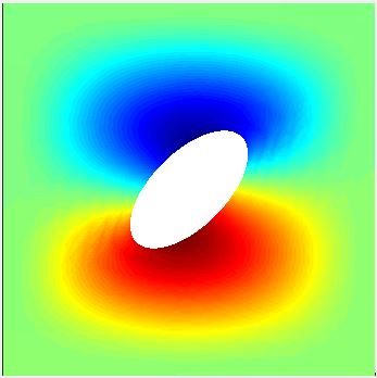
Next, the variation of critical buckling load with respect to change in eccentricity and angle of orientation of the cutout was analyzed. Table 3 presents the results for three different eccentricities. The results of the present method (LSM) are compared with those obtained using the Multi-Patch method (MPM)
|
|
| ||||||||||
| LSM | MPM | LSM | MPM | LSM | MPM | |||||||
| 0 | 0.381 | 0.379 | 0.413 | 0.402 | 0.633 | 0.633 | ||||||
| 15 | 0.395 | 0.390 | 0.443 | 0.438 | 0.659 | 0.653 | ||||||
| 30 | 0.427 | 0.421 | 0.532 | 0.525 | 0.729 | 0.715 | ||||||
| 45 | 0.469 | 0.460 | 0.641 | 0.630 | 0.809 | 0.807 | ||||||
3.4 Curvilinearly stiffened composite panels with a noncentric circular cutout
In this sub section, the influence of the noncentric circular cutouts on clamped stiffened composite panels is studied. The stiffener is isotropic with Young’s modulus = , Poisson’s ratio = and coefficient of thermal expansion = . The stiffness ratio and the area ratio are 5 and 0.1 respectively unless specified. To check the robustness of the level set method, results for clamped curvilinearly stiffened composite plate are compared with those obtained using ABAQUS. A noncentric circular cutout of radius with center at () was assumed. The curvilinear stiffener configuration was adopted from [39] and scaled proportionally to match the dimensions of the plate. From the ABAQUS library, the plate was meshed using 3040 S8R elements and curvilinear stiffener was meshed using 192 elements S8R elements (48 divisions along the arc length and 4 divisions along the depth direction). The IGA plate model was meshed using 4096 elements and the curvilinear stiffener using 32 elements. The critical buckling temperature result was observed to converge for this mesh configuration. The first five eigen buckling models were extracted for each case. As seen from Figure 4 the buckling mode shapes obtained using IGA and ABAQUS are comparable.
| Present | ABAQUS | |||
|---|---|---|---|---|
| Mode | ||||
| 1 |

|
0.426 |

|
0.420 |
| 2 |

|
0.535 |

|
0.523 |
| 3 |

|
0.708 |

|
0.698 |
| 4 |

|
0.910 |

|
0.906 |
| 5 |

|
1.070 |

|
1.007 |
3.5 Curvilinearly stiffened composite panels with an elliptical central cutout
In this section, results of curvilinearly stiffened composite panels with elliptical cutouts are presented. An ellipse of semi-major axis = 0.2 and semi-minor axis = 0.1 is considered for all cases. The variation of the critical thermal load with respect to angle orientations, ply orientations, stiffness ratios and different stiffener profiles (defined by Figure 6) are presented in Table 5 and Table 6. The results obtained using present method (LSM) and the Multi-Patch method (MPM) are in excellent agreement.
|
|
|
| |||||||||||||
| LSM | MPM | LSM | MPM | LSM | MPM | LSM | MPM | |||||||||
| 0 | 0.475 | 0.473 | 0.413 | 0.406 | 0.425 | 0.423 | 0.456 | 0.455 | ||||||||
| 45 | 0.507 | 0.497 | 0.494 | 0.488 | 0.370 | 0.366 | 0.436 | 0.434 | ||||||||
| 0 | 0.559 | 0.553 | 0.492 | 0.481 | 0.469 | 0.462 | 0.548 | 0.542 | ||||||||
| 45 | 0.598 | 0.592 | 0.595 | 0.590 | 0.406 | 0.395 | 0.525 | 0.521 | ||||||||
|
|
|
| |||||||||||||
| LSM | MPM | LSM | MPM | LSM | MPM | LSM | MPM | |||||||||
| 0 | 0.488 | 0.485 | 0.417 | 0.409 | 0.443 | 0.443 | 0.469 | 0.468 | ||||||||
| 45 | 0.509 | 0.509 | 0.502 | 0.495 | 0.83 | 0.378 | 0.448 | 0.449 | ||||||||
| 0 | 0.590 | 0.581 | 0.509 | 0.501 | 0.485 | 0.479 | 0.576 | 0.572 | ||||||||
| 45 | 0.619 | 0.612 | 0.618 | 0.610 | 0.410 | 0.405 | 0.560 | 0.554 | ||||||||
3.6 Curvilinearly stiffened composite panels with a complicated cutout
The present method is applied to analyze a stiffened laminated composite plate with a clover shaped cutout Figure 10. The cutout is a boolean of three circles of radius resulting in a clover shape. The center of circles A, B and C are at (), () and () respectively. Figure 10 shows the mesh plot for the plate geometry with the red region being the enriched elements.
To check the accuracy of the level set algorithm, results for clamped curvilinearly stiffened composite plate with a clover shaped cutout are compared with those obtained using ABAQUS. The curvilinear stiffener configuration was adopted from [39] and scaled proportionally to match the dimensions of the plate. From the ABAQUS library, the plate was meshed using 3040 S8R elements and curvilinear stiffener was meshed using 192 elements S8R elements (48 divisions along the arc length and 4 divisions along the depth direction). The IGA plate model was meshed using 4096 elements and the curvilinear stiffener using 32 elements. The first five eigen buckling models were extracted for each case. The buckling mode shapes obtained using the IGA approach are similar to those obtained using ABAQUS as can be seen from Figure 7.

| Present | ABAQUS | |||
|---|---|---|---|---|
| Mode | ||||
| 1 |

|
0.751 |

|
0.748 |
| 2 |

|
0.827 |

|
0.817 |
| 3 |

|
0.961 |

|
0.955 |
| 4 |

|
1.009 |

|
1 |
| 5 |

|
1.096 |

|
1.085 |
4 Advantages and limitations
One of the advantages of the level set method is their ability to use the same mesh controls on the plate for different types of cutouts. Figure 12 shows how the plate is discretized using x elements for circular as well as elliptical cutouts.


Discussions in Section 2.6 describe the creation of additional degrees of freedom while implementing the level set method. Table 8 shows the number of additional degrees of freedom created for each levels of refinement for a plate with a cutout of radius . It can be observed that the total degrees of freedom (nDoF = Total number of Gauss points x 5 ) increase much steeply than the additional degrees of freedom (Extra DoF) with increase in refinement levels.
| Refinement | nDoF | Extra DoF |
|---|---|---|
| 3 | 660 | 160 |
| 4 | 1920 | 300 |
| 5 | 6320 | 540 |
Next, computational cost due to these additional degrees of freedom was analyzed. Two cases were considered, a stiffened plate without any cutout (Case 1) and a stiffened plate with a central circular cutout of radius . The material properties, ply orientation and stiffener profile were the same as mentioned in Section 3.4. The computational time (in seconds) to perform the static and the eigenvalue analyses are compared for each case (Table 9, Figures 14 and 13). It is observed that the additional degrees of freedom have a much higher influence on the results from a static analysis as compared to the buckling analysis. However, the difference is very little for lower levels of refinement.
| Refinement | 4 | 5 | 6 | |||
|---|---|---|---|---|---|---|
| Static | Eigenvalue | Static | Eigenvalue | Static | Eigenvalue | |
| Case 1 | 0.0342 | 0.2045 | 0.2008 | 0.7087 | 1.2722 | 4.3813 |
| Case 2 | 0.0504 | 0.2244 | 0.2014 | 0.8724 | 4.5132 | 4.5352 |
5 Convergence studies
Convergence studies on a stiffened plate with a cutout are not as straightforward as a simple plate problem since the size of the cutout, size of the stiffener and the plate meshes all affect the results. We consider a stiffened plate with a central circular cutout. The material properties, ply orientation and stiffener profile were the same as mentioned in Section 3.4. For convergence studies with respect to the increasing cutout size, an unstiffened plate was considered. It can be observed from Figure 15 that the rate of convergence becomes slower with an increase in the cutout radius.
Figures 16, 17 and 18 present the change of critical buckling loads with respect to various stiffener and plate mesh sizes for cutouts of varying radii. It is observed that for cutouts with relatively smaller radius ( and ), for each refinement levels of the plate mesh, the results converge for the order of refinement of the stiffener mesh. It is also observed that the plate mesh density has a higher influence on the results compared to the stiffener mesh density. However, as the radius of the cutout is increased to , the stiffener mesh density starts to impact the convergence of results to a much higher degree (Figure 16).
6 Conclusions
This paper discusses the level set method which requires very little computational effort to obtain a mesh independent description of the geometrical shape of a complicated cutout.
The level sets discussed in this paper are implemented in the
form of a signed distance function which is both computationally inexpensive and easy to
implement. Such an implementation is greatly useful since the tensor product nature of the NURBS basis functions only allows for global refinement and therefore treating the trimmed objects such as internal cutouts is rather difficult. However, implementing the level set method obviates the use of trimmed NURBS surface to describe complex geometrical features like the cutouts. The efficiency of this method for thermal buckling analysis is described with the help of numerical examples for stiffened laminated plates containing complicated cutouts of various shapes and dimensions.
7 Acknowledgement
The authors would like to thank the Institute for Critical Technology and Applied Science (ICTAS) at Virginia Tech for providing financial support which made this research possible.
References
References
- [1] T. J. Hughes, J. A. Cottrell, Y. Bazilevs, Isogeometric analysis: CAD, finite elements, NURBS, exact geometry and mesh refinement, Computer Methods in Applied Mechanics and Engineering 194 (39-41) (2005) 4135–4195.
- [2] T. T. Yu, S. Yin, T. Q. Bui, S. Hirose, A simple FSDT-based isogeometric analysis for geometrically nonlinear analysis of functionally graded plates, Finite Elements in Analysis and Design 96 (C) (2015) 1–10.
- [3] S. De, K. Singh, B. Alanbay, R. K. Kapania, R. Aguero, Structural optimization of truck front-frame under multiple load cases, in: ASME International Mechanical Engineering Congress and Exposition, Vol. 52187, American Society of Mechanical Engineers, 2018, p. V013T05A039.
- [4] S. De, K. Singh, J. Seo, R. K. Kapania, E. Ostergaard, N. Angelini, R. Aguero, Structural design and optimization of commercial vehicles chassis under multiple load cases and constraints, in: AIAA Scitech 2019 Forum, 2019, p. 0705.
- [5] S. De, K. Singh, J. Seo, R. K. Kapania, E. Ostergaard, N. Angelini, R. Aguero, Lightweight chassis design of hybrid trucks considering multiple road conditions and constraints, World Electric Vehicle Journal 12 (1) (2021) 3.
- [6] S. De, K. Singh, J. Seo, R. Kapania, R. Aguero, E. Ostergaard, N. Angelini, Unconventional truck chassis design with multi-functional cross members, Tech. rep., SAE Technical Paper (2019).
- [7] M. Jrad, S. De, R. K. Kapania, Global-local aeroelastic optimization of internal structure of transport aircraft wing, in: 18th AIAA/ISSMO Multidisciplinary Analysis and Optimization Conference, 2017, p. 4321.
- [8] S. De, R. K. Kapania, Algorithms for 2d mesh decomposition in distributed design optimization (2021). arXiv:2002.00525.
- [9] Y. Bazilevs, V. M. Calo, T. J. R. Hughes, Y. Zhang, Isogeometric fluid-structure interaction: theory, algorithms, and computations, Computational Mechanics 43 (1) (2008) 3–37.
- [10] J. A. Evans, Y. Bazilevs, I. Babuška, T. J. Hughes, -Widths, -infs, and optimality ratios for the -version of the isogeometric finite element method, Computer Methods in Applied Mechanics and Engineering 198 (21-26) (2009) 1726–1741.
- [11] T. J. R. Hughes, A. Reali, G. Sangalli, Efficient quadrature for NURBS-based isogeometric analysis, Computer Methods in Applied Mechanics and Engineering 199 (5-8) (2010) 301–313.
- [12] F. Auricchio, F. Calabrò, T. J. Hughes, A. Reali, G. Sangalli, A simple algorithm for obtaining nearly optimal quadrature rules for NURBS-based isogeometric analysis, Computer Methods in Applied Mechanics and Engineering 249-252 (2012) 15–27.
- [13] Y. Bazilevs, C. Michler, V. M. Calo, T. J. Hughes, Isogeometric variational multiscale modeling of wall-bounded turbulent flows with weakly enforced boundary conditions on unstretched meshes, Computer Methods in Applied Mechanics and Engineering 199 (13-16) (2010) 780–790.
- [14] N. Valizadeh, T. Bui, V. Vu, H. Thai, M. Nguyen, Isogeometric Simulation for Buckling, Free and Forced Vibration of Orthotropic Plates, International Journal of Applied Mechanics 05 (02) (2013) 1350017.
- [15] S. Yin, J. S. Hale, T. Yu, T. Q. Bui, S. P. Bordas, Isogeometric locking-free plate element: A simple first order shear deformation theory for functionally graded plates, Composite Structures 118 (1) (2014) 121–138.
- [16] H. Kapoor, R. K. Kapania, S. R. Soni, Interlaminar stress calculation in composite and sandwich plates in NURBS Isogeometric finite element analysis, Composite Structures 106 (2013) 537–548.
- [17] H. Kapoor, R. K. Kapania, Geometrically nonlinear NURBS isogeometric finite element analysis of laminated composite plates, Composite Structures 94 (12) (2012) 3434–3447.
- [18] C. V. Verhoosel, M. A. Scott, T. J. R. Hughes, R. de Borst, An isogeometric analysis approach to gradient damage models, International Journal for Numerical Methods in Engineering 86 (1) (2011) 115–134. arXiv:1010.1724.
- [19] J. Lu, Isogeometric contact analysis: Geometric basis and formulation for frictionless contact, Computer Methods in Applied Mechanics and Engineering 200 (5-8) (2011) 726–741.
- [20] H. Nguyen-Xuan, L. V. Tran, C. H. Thai, S. Kulasegaram, S. P. Bordas, Isogeometric analysis of functionally graded plates using a refined plate theory, Composites Part B: Engineering 64 (2014) 222–234.
- [21] W. A. Wall, M. A. Frenzel, C. Cyron, Isogeometric structural shape optimization, Computer Methods in Applied Mechanics and Engineering 197 (33-40) (2008) 2976–2988.
- [22] J. Kiendl, K.-U. Bletzinger, J. Linhard, R. Wüchner, Isogeometric shell analysis with Kirchhoff–Love elements, Computer Methods in Applied Mechanics and Engineering 198 (49-52) (2009) 3902–3914.
- [23] J. Kiendl, Y. Bazilevs, M. C. Hsu, R. Wüchner, K. U. Bletzinger, The bending strip method for isogeometric analysis of Kirchhoff-Love shell structures comprised of multiple patches, Computer Methods in Applied Mechanics and Engineering 199 (37-40) (2010) 2403–2416.
- [24] S. Shojaee, E. Izadpanah, N. Valizadeh, J. Kiendl, Free vibration analysis of thin plates by using a NURBS-based isogeometric approach, Finite Elements in Analysis and Design 61 (2012) 23–34.
- [25] L. V. Tran, C. H. Thai, H. T. Le, B. S. Gan, J. Lee, H. Nguyen-Xuan, Isogeometric analysis of laminated composite plates based on a four-variable refined plate theory, Engineering Analysis with Boundary Elements 47 (2014) 68–81.
- [26] L. A. Piegl, W. Tiller, Geometry-based triangulation of trimmed NURBS surfaces, Computer-Aided Design 30 (1) (1998) 11–18.
- [27] S. Shojaee, N. Valizadeh, E. Izadpanah, T. Bui, T. V. Vu, Free vibration and buckling analysis of laminated composite plates using the NURBS-based isogeometric finite element method, Composite Structures 94 (5) (2012) 1677–1693.
- [28] R. Schmidt, R. Wüchner, K. U. Bletzinger, Isogeometric analysis of trimmed NURBS geometries, Computer Methods in Applied Mechanics and Engineering 241-244 (2012) 93–111.
- [29] S. S. Ghorashi, N. Valizadeh, S. Mohammadi, Extended isogeometric analysis for simulation of stationary and propagating cracks, International Journal for Numerical Methods in Engineering 89 (9) (2012) 1069–1101. arXiv:1010.1724.
- [30] E. Rank, M. Ruess, S. Kollmannsberger, D. Schillinger, A. Düster, Geometric modeling, isogeometric analysis and the finite cell method, Computer Methods in Applied Mechanics and Engineering 249-252 (2012) 104–115.
- [31] D. Schillinger, L. Dedè, M. A. Scott, J. A. Evans, M. J. Borden, E. Rank, T. J. Hughes, An isogeometric design-through-analysis methodology based on adaptive hierarchical refinement of NURBS, immersed boundary methods, and T-spline CAD surfaces, Computer Methods in Applied Mechanics and Engineering 249-252 (2012) 116–150.
- [32] B. Devarajan, D. Locatelli, R. Kapania, R. Meritt, Thermo-mechanical analysis and design of threaded fasteners, in: 2016 AIAA/ASCE/AHS/ASC Structures, Structural Dynamics, and Materials Conference, 2016, p. 0579.
- [33] Q. Li, B. Devarajan, X. Zhang, R. Burgos, D. Boroyevich, P. Raj, Conceptual design and weight optimization of aircraft power systems with high-peak pulsed power loads, in: SAE Technical Paper, SAE International, 2016, p. 10. doi:10.4271/2016-01-1986.
- [34] A. K. Noor, W. S. Burton, C. W. Bert, Computational Models for Sandwich Panels and Shells, Applied Mechanics Reviews 49 (3) (1996) 155.
- [35] W. S. Burton, A. K. Noor, Three Dimensional Solutions for Thermomechanical Stresses in Sandwich Panels and Shells, Journal of Engineering Mechanics 120 (10) (1994) 2044–2071.
- [36] A. K. Noor, W. S. Burton, Three Dimensional Solutions for Thermal Buckling of Multilayered Anisotropic Plates, Journal of Engineering Mechanics 118 (4) (1992) 683–701.
- [37] M. Mukhopadhyay, A. Mukherjee, Finite element buckling analysis of stiffened plates, Computers & structures 34 (6) (1990) 795–803.
- [38] B. G. Prusty, S. Satsangi, Finite element transient dynamic analysis of laminated stiffened shells, Journal of Sound and Vibration 248 (2) (2001) 215–233.
- [39] A. Y. Tamijani, R. K. Kapania, Buckling and Static Analysis of Curvilinearly Stiffened Plates Using Mesh-Free Method, AIAA Journal 48 (12) (2010) 2739–2751.
- [40] W. Zhao, R. K. Kapania, Buckling analysis of unitized curvilinearly stiffened composite panels, Composite Structures 135 (2016) 365–382.
- [41] J. H. Robinson, S. Doyle, G. Ogawa, M. Baker, S. De, M. Jrad, R. K. Kapania, Aeroelastic optimization of wing structure using curvilinear spars and ribs (sparibs), in: 17th AIAA/ISSMO Multidisciplinary Analysis and Optimization Conference, 2016, p. 3994.
- [42] S. De, M. Jrad, D. Locatelli, R. K. Kapania, M. Baker, Sparibs geometry parameterization for wings with multiple sections using single design space, in: 58th AIAA/ASCE/AHS/ASC Structures, Structural Dynamics, and Materials Conference, 2017, p. 0570.
- [43] S. De, Structural modeling and optimization of aircraft wings having curvilinear spars and ribs (sparibs), Ph.D. thesis, Virginia Tech (2017).
- [44] P. Shi, R. K. Kapania, C. Y. Dong, Vibration and Buckling Analysis of Curvilinearly Stiffened Plates Using Finite Element Method, AIAA Journal 53 (5) (2015) 1319–1335.
- [45] P. Hao, B. Wang, K. Tian, G. Li, X. Zhang, Optimization of curvilinearly stiffened panels with single cutout concerning the collapse load, International Journal of Structural Stability and Dynamics 16 (07) (2016) 1550036.
- [46] B. Devarajan, R. K. Kapania, Thermal buckling of curvilinearly stiffened laminated composite plates with cutouts using isogeometric analysis, Composite Structures (2020) 111881.
- [47] B. Devarajan, Thermomechanical and Vibration Analysis of Stiffened Unitized Structures and Threaded Fasteners, vtechworks.lib.vt.edu, 2019.
- [48] L. L. Piegl, W. Tiller, The NURBS Book, Vol. 28, Springer Science & Business Media, 1996. arXiv:arXiv:1011.1669v3.
- [49] L. V. Tran, M. A. Wahab, S. E. Kim, An isogeometric finite element approach for thermal bending and buckling analyses of laminated composite plates, Composite Structures 179 (2017) 35–49.
- [50] C. Sarath Babu, T. Kant, Refined higher order finite element models for thermal buckling of laminated composite and sandwich plates, Journal of Thermal Stresses 23 (2) (2000) 111–130.
- [51] T. Kant, C. S. Babu, Thermal buckling analysis of skew fibre-reinforced composite and sandwich plates using shear deformable finite element models, Composite Structures 49 (1) (2000) 77–85.
- [52] A. Avci, S. Kaya, B. Daghan, Thermal buckling of rectangular laminated plates with a hole, Journal of Reinforced Plastics and Composites 24 (3) (2005) 259–272.