End-Effector Stabilization of a 10-DOF Mobile Manipulator using Nonlinear Model Predictive Control
Abstract
Motion control of mobile manipulators (a robotic arm mounted on a mobile base) can be challenging for complex tasks such as material and package handling. In this paper, a task-space stabilization controller based on Nonlinear Model Predictive Control (NMPC) is designed and implemented to a 10 Degrees of Freedom (DOF) mobile manipulator which consists of a 7-DOF robotic arm and a 3-DOF mobile base. The system model is based on kinematic models where the end-effector orientation is parameterized directly by a rotation matrix. The state and control constraints as well as singularity constraints are explicitly included in the NMPC formulation. The controller is tested using real-time simulations, which demonstrate high positioning accuracy with tractable computational cost.
keywords
Mobile manipulator, task-space control, non-linear model predictive control1 Introduction
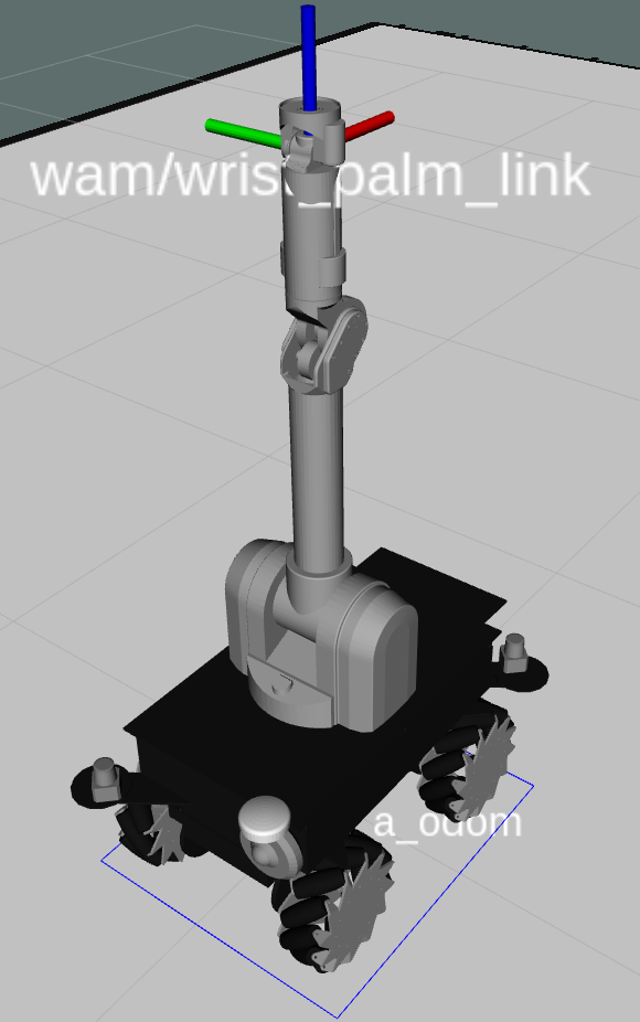
The use of mobile manipulators in industry has increased drastically over the past decade. Mobile manipulators combine the advantages of both wheeled robots and robotic arms; thus, they have an expandable workspace and operational versatility through perception, object manipulation, and mobility. Such robots can be used in material handling, wall painting, as well as inspection and repairs, see, e.g. (Bostelman et al. 2016) for a survey. Operating such systems requires safe navigation in possibly dynamic environments and precise object manipulation. In this paper, we focus on stabilizing the end-effector of a 10-DOF mobile manipulator shown in Fig. 1. The mobile manipulator is built by integrating the Summit-XLS mobile robot with meccanum wheels manufactured by Robotnik and the 7-DOF Barrett WAM robotic arm.
The separate control of mobile robots and robotic arms is studied extensively in the literature. The considered control problems can be categorized under point-stabilization, trajectory tracking, and path following. The commonly used control techniques include feedback linearization (d’Andréa Novel et al. 1995), robust control (Koubaa et al. 2013), fuzzy based feedback linearization (Piltan et al. 2013), adaptive control (Pourboghrat and Karlsson 2002; Slotine and Weiping 1988), and model predictive control (MPC) (Faulwasser et al. 2016; Mehrez et al. 2020).
Several studies that consider controlling mobile manipulators as a combined system also exist. For example, Silva and Adorno 2016 designed a whole-body controller based on feedback linearization controlling the end-effector pose of a mobile manipulator. The controller was tested on a 7-DOF mobile manipulator. Patel et al. 2017 proposed an adaptive backstepping control for the trajectory tracking of mobile manipulators. Mishra et al. 2018 developed a robust nonlinear controller with uncertainty estimator; the controller was validated through simulations for a 7-DOF mobile manipulator. Furthermore, Avanzini et al. 2016 used linear MPC for developing a reactive constrained controller of an omnidirectional mobile base with a 5-DOF robotic arm. All the aforementioned studies considered mobile manipulators with non-redundant arms. This simplifies the problem due to the presence of a closed-form inverse kinematics solutions for such arms. Thus, the control of the mobile manipulator end-effector can be designed in the configuration (joint) space by utilizing a separate closed-form inverse kinematics module, see, e.g. (Avanzini et al. 2016).
 |
 |
MPC is popular in the field of controls because of its ability to handle constrained possibly nonlinear mutli-input-multi-output (MIMO) systems. In MPC, a cost function characterizing the control objective is minimized using an open-loop control sequence or function while state and control constraints are considered. The first part of the resulting open-loop control is then applied to the system. Finally, the process is repeated every decision instant, see, e.g. (Allgöwer and Zheng 2012).
In this paper, we use a nonlinear model predictive control (NMPC) scheme to stabilize the end-effector of a 10-DOF mobile manipulator; here, we first formulate the task-space kinematic model, where the overall system rotations are expressed using the 3D special orthogonal representation. Then, this model is used for state prediction in the NMPC formulation, which considers state and control constraints as well as kinematic singularity constraints. The proposed NMPC controller is implemented using Robot Operating System (ROS) (Quigley et al. 2009) and the efficacy of the proposed controller is demonstrated through a series of real-time simulations using Gazebo dynamic simulator (Koenig and Howard 2004). The results show highly-accurate and smooth stabilization of the end-effector as well as computational cost, which meets the real-time requirements.
The remainder of the paper is organized as follows: the model used to implement the NMPC is explained in Section 2 followed by the optimal control (OCP) problem formulation in Section 3. In Section 4, the simulation testbed used to validate the proposed controller is introduced and then the acquired results are shown in Section 5. Finally, in Section 6 conclusions are stated and the future work is summarized.
2 Mobile Manipulator Modeling
In this section, we, first, show the notations used in the paper. Then, we present the kinematic model of the synthesized mobile manipulator.
2.1 Notations
and denote the sets of natural and real numbers, respectively, is the norm defined as , is the squared norm weighted by and is calculated as , the matrix trace operator is denoted by , denotes that is a positive definite matrix, is the identity matrix, denotes an matrix with all entries of zeros, and and denote the special orthogonal and special Euclidean groups, respectively.
2.2 Kinematic Model of the holonomic Mobile Base
The mobile base of the considered mobile manipulator is a holonomic mobile robot with meccanum wheels. Holonomic mobile robots possess an extra degree of maneuverability when compared to the non-holonomic robots (Siegwart et al. 2011).
The discrete-time kinematic model of the mobile base is given by
| (1) |
where is the pose of the mobile base in the inertial frame, are the two Cartesian planar coordinates and is the yaw angle of the mobile base. is the robot input speeds, is a nonlinear mapping, is the -axis rotation matrix, and is the sampling time.
The state constraint set is a compact set defined as
where are the lower and upper bounds of the Cartesian coordinates and , respectively.
The relation between the robot input speeds and wheel speeds , for meccanum wheels robots, can be stated as (Lynch and Park 2017)
| (2) |
where is the mecanum wheel radius, and are half of the wheelbase and the trackwidth, respectively. Consequently, the control constraint set is a compact set defined as
| (3) |
where is the rated speed of the wheel motors.
2.3 Kinematic Model of the Robotic Arm
The robotic arm mounted on the aforementioned mobile base is a 7-DOF WAM arm by Barrett Technology (Barrett 2018a). The end-effector pose of the robotic arm is denoted by , where is the end-effector position in the robotic arm base frame represented in the Cartesian coordinates and is the end-effector orientation. The end-effector orientation can be represented using several methods as discussed in (Campa and De La Torre 2009). Here, we use the group to avoid representation singularities and error definition discontinuities. To do so, we define the mapping function , such that, for a rotation matrix ,
| (4) |
where , , is the -th column vector of the rotation matrix . Thus, the orientation vector is , and is the rotation matrix of the end-effector in the base frame of the robotic arm.
Using such a representation, the kinematic model of the robotic arm can be described using the analytical Jacobian of the forward kinematics transformation matrix derived using the DH-parameters of the robotic arm, (see Barrett 2018b for the DH-parameters of the considered robotic arm), as
| (5) |
where is the state vector defined using from (4), is the joint angles vector, is the joint velocities vector, and, the analytical Jacobian is given by .
The constraint sets for the end-effector , joint angles , and joint velocities are defined by
where and denote the lower and upper limits of the joint angles, respectively.
In order to be able to keep track of the joint angles and consider joint constraints, we extend system (5) to
| (6) |
where is the concatenated state vector, and is the state constraint set for the new augmented model and is defined as .
2.4 Mobile Manipulator Kinematic Model
The model of the mobile manipulator can now be derived using the model of the mobile base and the robotic arm. First, we map the velocity components of the mobile base to the end-effector linear speeds in the inertial frame, i.e. we have
| (7) |
where is the linear velocity of the end-effector caused by the mobile base in the inertial frame, and is the upper left sub-matrix of shown in Eq. (2.2). Note that is the orientation of the mobile robot, which can be determined through the localization feedback. are the position of the end-effector in the mobile base frame and can be determined from the forward kinematics transformation matrix .
Second, to calculate the angular velocity of the mobile robot in , we need to calculate the derivative of the rotation matrix . As mentioned in (Campa and De La Torre 2009), the derivative of a rotation matrix can be calculated as
| (8) |
where is the skew symmetric matrix form of the angular velocity vector , where and are the three angular velocities around the principle axes and , respectively. Using the properties of the skew-symmetric matrix, Eq. (8) can be written as
| (9) |
where is the rate of change of the end-effector orientation due to the mobile base rotation. Moreover, is the -th column vector of in the skew symmetric form.
Since we do not consider any other angular velocities than for the mobile base, the first two columns of in (9) will be zeros. Consequently, reads
| (10) |
where we exploit the fact that for an omnidirectional mobile robot is the control action shown in Eq. (2.2).
Using Eq. (7) and (10), in addition to the kinematic model in Eq. (6), the kinematic model of the whole mobile manipulator can be written as
| (11) | ||||
where is the concatenated state vector of the mobile manipulator, is the concatenated control vector. Here, is the end-effector pose vector in the inertial frame.
The model stated in (11) is the complete kinematic model of the considered 10-DOF mobile manipulator consisting of a 3-DOF holonomic mobile base and a 7-DOF robotic arm. The constraints over the developed kinematic model can now be defined as
| (16) | ||||
Finally, the end-effector pose feedback can be determined by the pose of the mobile robot determined through the use of a localization algorithm (Osman et al. 2019) and the forward kinematic equations of the robotic arm .
3 Nonlinear Model Predictive Control
In this section, we formulate an NMPC scheme for the end-effector pose stabilization of the mobile manipulator. To this end, we define
as the sequences of controls and states over the prediction horizon , respectively. As standard in NMPC, these sequences are used to form the quadratic cost function
| (17) |
where and are the weighting matrices of the quadratic cost function, and is the terminal cost of the cost function. is the translational error of the end-effector pose defined as , where is the reference position, and is the orientation error of the end-effector pose defined as
| (18) |
where is the reference orientation, and is the orientation of the end-effector in the inertial frame calculated as . is determined using a localization algorithm of the mobile robot and is the rotation matrix from the mobile robot to the end-effector and is calculated from the forward kinematics of the robotic arm, i.e. .
Using the cost function in Eq. (3), the NMPC optimal control problem can be formulated as:
| (19a) | ||||||
| subject to | (19b) | |||||
| (19c) | ||||||
| (19d) | ||||||
| (19e) | ||||||
where is a threshold for avoiding singular configurations of the robotic arm.
OCP (19) is converted to a nonlinear programming problem (NLP) using the direct multiple-shooting method (Albersmeyer and Diehl 2010). Here, both the control sequence as well as the state sequence are considered as decision variables in the optimization problem. Moreover, the system model is considered as an optimization constraint as formulated by Eq. (19b). Multiple-shooting discretization technique provides a more computationally efficient solution to OCP (19) when compared with other discretization techniques, e.g. single-shooting, see (Albersmeyer and Diehl 2010) for more details. Finally, state and control constrains are considered by means of Eq. (19c) and (19d). Note that the inequality constraint (19e) is added to avoid kinematic singularities of the robotic arm through operation. This is accomplished through ensuring that the pseudo-inverse of the robot arm Jacobian matrix is always invertible and, thus, singular configurations are avoided.
The feedback control law can now be stated as
i.e. the feedback control is the first element in the optimal control sequence . Moreover, the resulting feedback system can be stated as
4 Real-Time Simulation Testbed and Simulation Scenarios
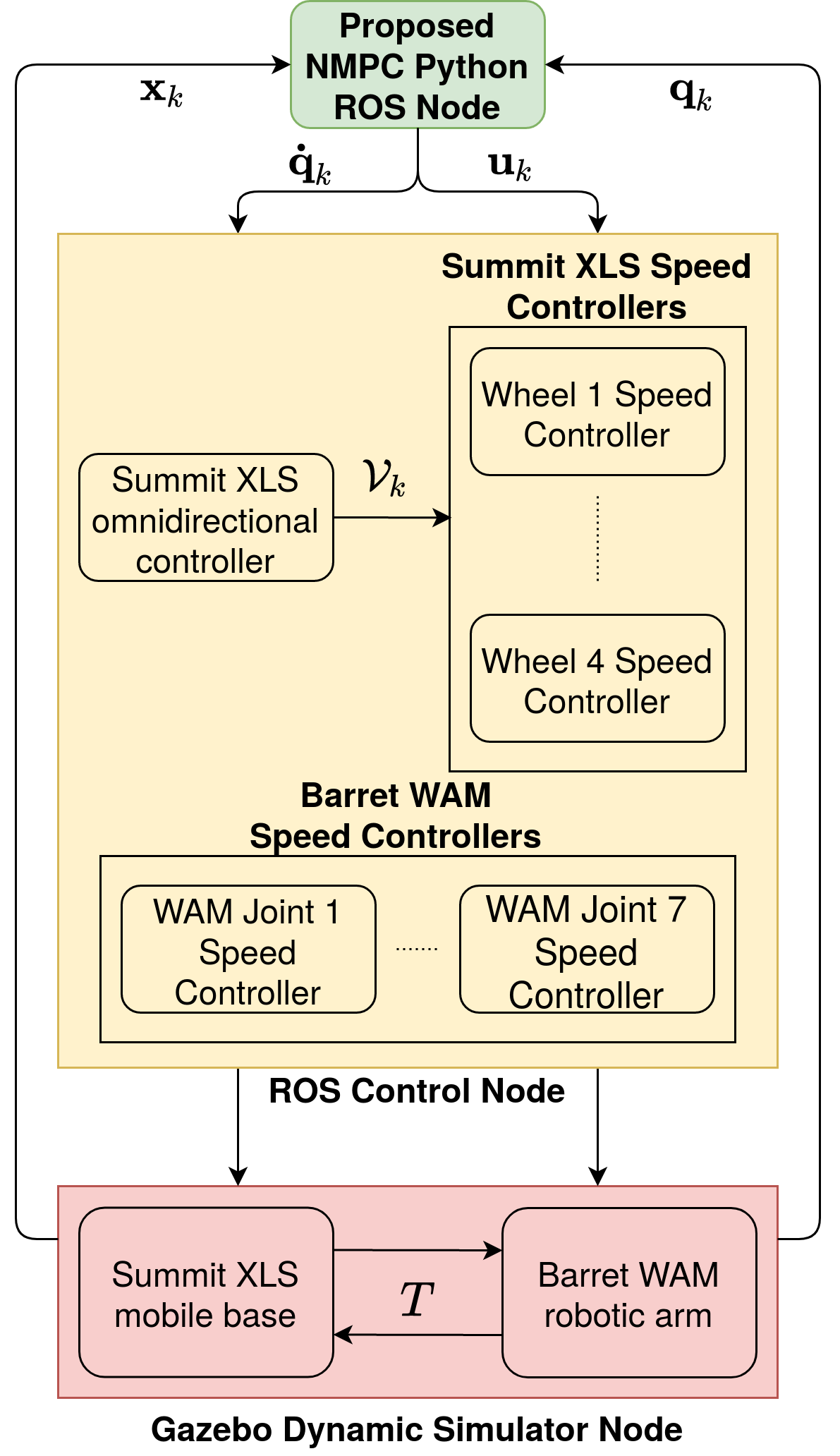
The simulation testbed of the considered mobile manipulator is created by synthesizing the ‘‘urdf” models of both the Barret WAM arm and the Summit XLS mobile robot in a ROS/Gazebo simulation environment11 1 urdf: universal robotic description format.. Here, the transformation and the constraints between the two models are defined based on the actual physical system, see Fig. 1. Moreover, the proposed NMPC controller is programmed in python programming language and integrated with the simulation environment via a ROS-node. Here, OCP (19) is formulated symbolically using the numerical optimization software tool CasADi (Andersson et al. 2018). Additionally, OCP (19) is solved using the interior-point optimization method via the open source solver IPOPT (Wächter and Biegler 2006). The overall block-diagram of the ROS/Gazebo real-time simulation environment is illustrated in Fig. 2.
| Scenario | Initial States | Reference Pose |
|---|---|---|
| 1 | ||
| 2 | ||
| 3 | ||
| 4 | ||
| 5 | ||
| 6 | ||
| 7 | ||
| 8 |
The scenarios shown in Table 1 were used to validate the proposed controller. Initial and set-point references shown are presented using the Z-Y-X Euler angles to simplify the presentation. In all scenarios, the sampling time is sec, the prediction horizon is , and the weighting matrices are , and . Furthermore, the constraints set defined in (16) is chosen as
where the arm joint angles limits set is given by
Here, the joint angle limits are adapted from the arm specifications (Barrett 2018a). Finally, the limit of the joints speeds is chosen as rad/sec and the angular speed limit of the mobile robot wheels is chosen as rad/sec.
5 Results and Discussion
In this section, we show the closed-loop results of the mobile manipulator under the NMPC controller for all the scenarios stated in Table 1. Fig. 3 shows the trajectory of the end-effector through each simulation case. As shown in the figure, the controller successfully stabilized the end-effector of the mobile manipulator to the desired position.

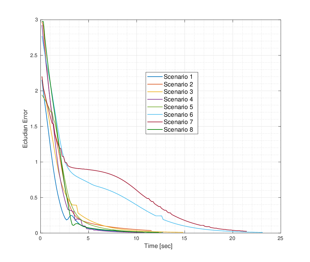
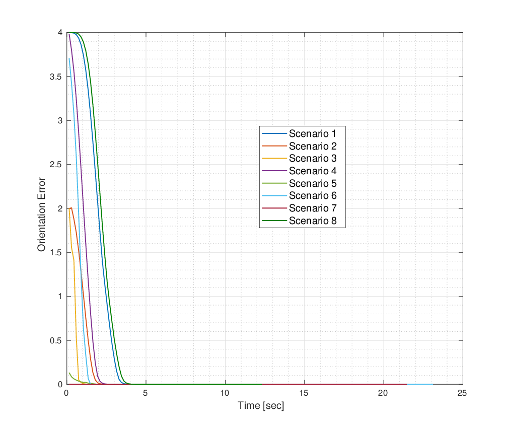
The performance of the NMPC controller is evaluated by both position and orientation errors of the end-effector with respect to the reference pose. The positional error is measured by the Euclidean distance between the end-effector position and the reference position, while the orientation error is measured by the evaluation metric
| (20) |
where the trace of the error rotation matrix is used. In essence, Eq. (20) indicates that the orientation error converges to zero as the the end-effector orientation converges to the reference orientation .
As shown in Fig. 4, the positional error converges to zero for all scenarios considered. Note that in scenarios and , the settling time of the controller is relatively larger than that for the other scenarios due to the joints limits. In these two cases, the mobile manipulator had to take a longer maneuver to reach the required position and orientation without violating any joint limits. In Fig. 5, the orientation error of the end-effector, i.e. , is shown. The error is calculated using the evaluation metric stated in (20). As can be seen in the figure, the controller managed to quickly achieve all the required orientations.
All the real-time simulations were executed using an Intel Core i CPU with GHz processor. The average computation time of OCP (19) throughout all the simulation scenarios was ms with a maximum computation time of ms and a standard deviation of ms. Considering that the sampling time used is ms, the computational results suggest that the proposed NMPC algorithm meets the real-time implementation requirements while generating feasible solutions.
6 Conclusion and Future Work
In this paper, we proposed an NMPC controller for end-effector stabilization of a 10-DOF mobile manipulator. We used the kinematic models for both the mobile base and the robot arm to realize a task-space control for the end-effector of the mobile manipulator. Required constraints were directly considered, which include the joint limits and the manipulator singularity. We remark that using the developed model along with NMPC, the stabilization of the end-effector was achieved without the need of any inverse kinematics solvers. Therefore, the proposed controller is a stand-alone high level controller, which only requires the localization feedback of the mobile base and the joint positions feedback of the robotic arm to operate on the mobile manipulator.
The controller was validated through real-time dynamic simulation scenarios. The results showed efficacy and efficiency of the proposed NMPC controller. Throughout all the designed scenarios, the controller managed to smoothly stabilize the end-effector to the required pose.
As for the future work, experiments using the real platform in Fig. 1 will be designed and performed to further validate the controller.
Acknowledgments
We acknowledge the support of the Natural Sciences and Engineering Research Council of Canada (NSERC), [funding reference numbers PDF-532957-2019 (M.W. Mehrez), STPGP 506987 (S. Jeon)].
References
- Albersmeyer and Diehl (2010) Albersmeyer, J. and Diehl, M. (2010). The lifted newton method and its application in optimization. SIAM Journal on Optimization, 20(3), 1655–1684.
- Allgöwer and Zheng (2012) Allgöwer, F. and Zheng, A. (2012). Nonlinear model predictive control, volume 26. Birkhäuser.
- Andersson et al. (2018) Andersson, J.A.E., Gillis, J., Horn, G., Rawlings, J.B., and Diehl, M. (2018). CasADi – A software framework for nonlinear optimization and optimal control. Mathematical Programming Computation.
- Avanzini et al. (2016) Avanzini, G.B., Zanchettin, A.M., and Rocco, P. (2016). Reactive constrained model predictive control for redundant mobile manipulators. In Intelligent Autonomous Systems 13, 1301–1314. Springer.
- Barrett (2018a) Barrett (2018a). WAM Arm Specifications. URL https://advanced.barrett.com/wam-arm-1.
- Barrett (2018b) Barrett (2018b). WAM Arm User Guide. URL http://www.me.unm.edu/~starr/research/WAM_UsersGuide_AE-00.pdf.
- Bostelman et al. (2016) Bostelman, R., Hong, T., and Marvel, J. (2016). Survey of research for performance measurement of mobile manipulators. Journal of Research of the National Institute of Standards and Technology, 121, 342–366.
- Campa and De La Torre (2009) Campa, R. and De La Torre, H. (2009). Pose control of robot manipulators using different orientation representations: A comparative review. In 2009 American Control Conference, 2855–2860. IEEE.
- d’Andréa Novel et al. (1995) d’Andréa Novel, B., Campion, G., and Bastin, G. (1995). Control of nonholonomic wheeled mobile robots by state feedback linearization. The International journal of robotics research, 14(6), 543–559.
- Faulwasser et al. (2016) Faulwasser, T., Weber, T., Zometa, P., and Findeisen, R. (2016). Implementation of nonlinear model predictive path-following control for an industrial robot. IEEE Transactions on Control Systems Technology, 25(4), 1505–1511.
- Koenig and Howard (2004) Koenig, N. and Howard, A. (2004). Design and use paradigms for gazebo, an open-source multi-robot simulator. In 2004 IEEE/RSJ International Conference on Intelligent Robots and Systems (IROS)(IEEE Cat. No. 04CH37566), volume 3, 2149–2154. IEEE.
- Koubaa et al. (2013) Koubaa, Y., Boukattaya, M., and Damak, T. (2013). Robust control of wheeled mobile robot in presence of disturbances and uncertainties. In 14th International Conference on Sciences and Techniques of Automatic Control & Computer Engineering-STA’2013, 274–280. IEEE.
- Lynch and Park (2017) Lynch, K.M. and Park, F.C. (2017). Modern Robotics: Mechanics, Planning, and Control. Cambridge University Press, New York, NY, USA, 1st edition.
- Mehrez et al. (2020) Mehrez, M.W., Worthmann, K., Cenerini, J.P., Osman, M., Melek, W.W., and Jeon, S. (2020). Model predictive control without terminal constraints or costs for holonomic mobile robots. Robotics and Autonomous Systems, 127, 103468.
- Mishra et al. (2018) Mishra, S., Londhe, P., Mohan, S., Vishvakarma, S., and Patre, B. (2018). Robust task-space motion control of a mobile manipulator using a nonlinear control with an uncertainty estimator. Computers & Electrical Engineering, 67, 729–740.
- Osman et al. (2019) Osman, M., Hussein, A., and Al-Kaff, A. (2019). Intelligent vehicles localization approaches between estimation and information: A review. In 2019 IEEE International Conference of Vehicular Electronics and Safety (ICVES), 1–8. IEEE.
- Patel et al. (2017) Patel, B., Pan, Y.J., and Ahmad, U. (2017). Adaptive backstepping control approach for the trajectory tracking of mobile manipulators. In 2017 IEEE International Conference on Robotics and Biomimetics (ROBIO), 1769–1774. IEEE.
- Piltan et al. (2013) Piltan, F., Yarmahmoudi, M., Mirzaie, M., Emamzadeh, S., and Hivand, Z. (2013). Design novel fuzzy robust feedback linearization control with application to robot manipulator. International Journal of Intelligent Systems and Applications, 5(5), 1.
- Pourboghrat and Karlsson (2002) Pourboghrat, F. and Karlsson, M.P. (2002). Adaptive control of dynamic mobile robots with nonholonomic constraints. Computers & Electrical Engineering, 28(4), 241–253.
- Quigley et al. (2009) Quigley, M., Gerkey, B., Conley, K., Faust, J., Foote, T., Leibs, J., Berger, E., Wheeler, R., and Ng, A. (2009). Ros: an open-source robot operating system. In Proc. of the IEEE Intl. Conf. on Robotics and Automation (ICRA) Workshop on Open Source Robotics. Kobe, Japan.
- Siegwart et al. (2011) Siegwart, R., Nourbakhsh, I.R., Scaramuzza, D., and Arkin, R.C. (2011). Introduction to autonomous mobile robots. MIT press.
- Silva and Adorno (2016) Silva, F.F.A. and Adorno, B.V. (2016). Whole-body control of a mobile manipulator using feedback linearization based on dual quaternions. In 2016 XIII Latin American Robotics Symposium and IV Brazilian Robotics Symposium (LARS/SBR), 293–298. IEEE.
- Slotine and Weiping (1988) Slotine, J.J. and Weiping, L. (1988). Adaptive manipulator control: A case study. IEEE transactions on automatic control, 33(11), 995–1003.
- Wächter and Biegler (2006) Wächter, A. and Biegler, L.T. (2006). On the implementation of an interior-point filter line-search algorithm for large-scale nonlinear programming. Mathematical Programming, 106(1), 25–57.