A silicon singlet-triplet qubit driven by spin-valley coupling
Abstract
Spin-orbit effects, inherent to electrons confined in quantum dots at a silicon heterointerface, provide a means to control electron spin qubits without the added complexity of on-chip, nanofabricated micromagnets or nearby coplanar striplines. Here, we demonstrate a novel singlet-triplet qubit operating mode that can drive qubit evolution at frequencies in excess of 200 MHz. This approach offers a means to electrically turn on and off fast control, while providing high logic gate orthogonality and long qubit dephasing times. We utilize this operational mode for dynamical decoupling experiments to probe the charge noise power spectrum in a silicon metal-oxide-semiconductor double quantum dot.
In addition, we assess qubit frequency drift over longer timescales to capture low-frequency noise. We present the charge noise power spectral density up to 3 MHz, which exhibits a dependence consistent with , over 9 orders of magnitude in noise frequency.
I Introduction
Qubits based on the spins of electrons confined to gate-defined quantum dots (QDs) in silicon metal-oxide-semiconductor (MOS) structures have developed into a promising platform for quantum information processing. High-quality single-qubit Veldhorst2014; Yang2019 and two-qubit gates Veldhorst2015aa; Huang2019; Yang2019b have been demonstrated, and device manufacture is generally compatible with available silicon microelectronics fabrication methods. Qubit control techniques demonstrated in silicon MOS have utilized electron spin resonance (ESR) with microwave strip-lines Veldhorst2014; Yang2019; Petit2019, electric dipole spin resonance (EDSR) using micromagnets Yang2019b or the intrinsic spin-orbit coupling (SOC) at the Si/SiO2 interface Jock2018; Corna2018; Harvey-Collard2019; Corna2018. Making use of interfacial SOC has the appeal of driving qubit evolution with electrical-only control without reliance on the added fabrication constraints of micromagnets or on-chip microwave strip-lines.
Confining electrons to quantum dots at the Si/SiO2 interface has been shown to produce spin-orbit coupling that is stronger than that of bulk Si Veldhorst2015; Jock2018; Harvey-Collard2019; Ferdous2018; Tanttu2019. Recent observations have demonstrated that the broken crystal symmetry at the silicon heterointerface and interactions with excited valley states lead to this enhanced SOC. These effects contribute to variation of the -factor in QDs Veldhorst2015; Jock2018; Ferdous2018; Fogarty2018; Tanttu2019; Harvey-Collard2019. The -factor difference between neighboring QDs has proven to be a valuable resource, able to drive the evolution of spin qubits encoded into a singlet-triplet subspace Jock2018; Harvey-Collard2019; Jirovec2021. Spin-valley coupling is known to enhance electron spin relaxation (shorter spin T1) near the “hot spot” when the valley splitting, , is comparable to the electronic Zeeman splitting, , in a QD, where is the Bohr magneton and is the applied external magnetic field Yang2013; Borjans2019; Hollmann2019; Zhang2020. This enhanced relaxation mechanism has been used to study valley splitting Yang2013; Hollmann2019; Zhang2020 and intervalley spin-orbit coupling in silicon QD devices Yang2013; Hao2014; Zhang2020. Additionally, spin-valley coupling has been proposed as a mechanism to coherently control electron spins in silicon QDsHuang2017; Bourdet2018; Bourdet2018b. This could potentially provide an intrinsic qubit control mechanism without the added fabrication complexity of integrated features such microwave striplines and micromagnets. However, coherent qubit control using spin-valley coupling has yet to be experimentally demonstrated in a silicon spin qubit.
In this work, we utilize the intervalley spin orbit interaction near the spin-valley hot spot in a silicon MOS QD and demonstrate the ability to drive singlet-triplet rotations in excess of 200 MHz using the intervalley spin-orbit interaction. We exploit these fast rotations near the hot spot to enable unique qubit operation with high-speed all-electrical modulation between qubit logic gates and high orthogonality of control axes through electrical control of the valley splitting. These fundamental measurements establish this qubit as a candidate for future quantum information processing systems. We take advantage of this novel operating mode to investigate the charge noise power spectral density (PSD) in this device. We use the noise filtering properties of a Carr–Purcell–Meiboom–Gill (CPMG) dynamical decoupling pulse sequence to decouple the qubit from charge noise experienced during the spin-spin exchange interaction. Combined with long-timescale measurements of drift in the frequency of exchange driven ST qubit rotations, we find that charge noise in this device exhibits a power spectral density consistent with over 9 decades of frequency.
II Results
II.1 Intervalley spin-orbit interaction

The silicon MOS double-quantum dot (DQD) used in this work is illustrated in Fig. 1(a). We operate the device near the (N,N) = (4,0)-(3,1) charge transition. Two electrons on QD1 form a spin paired closed shell Higginbotham2014; Harvey-Collard2017; Leon2019. The interaction between the remaining two electrons is electrically controlled via the detuning bias, , between the QDs. For shallow detuning, there is significant electronic wave function overlap between the two electrons and the exchange energy, , is the dominant interaction. When the two electrons are well separated in the deep tuning regime, is small and the dominant interaction is set by the interfacial SOC, which results in distinct Zeeman energies in each QD Jock2018; Jones2018; Fogarty2018; Ferdous2018; Harvey-Collard2019; Tanttu2019. The system is initialized by loading a (4,0) singlet ground state, then quickly transferring an electron to the (3,1) charge configuration to produce a (3,1) singlet state (i.e. rapid adiabatic passage). Here, SOC in the DQD will drive rotations between (3,1) singlet and triplet states. We then rapidly return the system to the (4,0) charge sector, where Pauli spin blockade, combined with an enhanced latching mechanism Harvey-Collard2018a, is used to read out the spin state of the two-electron system in the single-triplet basis. In Fig. 2(b) we show the fast Fourier transform (FFT) of SOC-driven rotations as the external magnetic field is swept along the [010] crystallographic direction. For low field strengths (), we observe a weak increase in evolution frequency with applied magnetic field, consistent with previous experiments Jock2018; Tanttu2019; Harvey-Collard2019. In this regime an intravalley spin-orbit mechanism generates a difference in effective electron -factor between the two QDs which lifts the degeneracy of the =0 states, and , driving rotations between (3,1) and (3,1) Jock2018. As is further increased, we observed an unexpected rapid rise in rotation frequency with a sharp peak near = 0.64 T. As discussed further below, these fast rotations are driven by an intervalley spin-orbit interaction which involves a coupling between distinct valley states having opposite spin. The peak position corresponds to the magnetic field at which the excited valley state, , crosses the ground state =0 manifold of the two-electron system, , as illustrated in Fig. 2(c), often referred to as the spin-valley “hot spot”.

Previous work has studied this regime in silicon QDs through single spin relaxation rates Yang2013; Hao2014; Borjans2019; Hollmann2019; Zhang2020. Our approach of studying coherent rotations driven by the intervalley spin-orbit interaction yields new insight into the intervalley spin-orbit interaction and its dependence on applied magnetic field. Here we provide an intuitive three-level picture of the system that describes the physics of the frequency dependence around the hot spot in Fig. 2(b) and explains how the system can be used for a novel qubit operating mode.
In the two-electron DQD system, the intervalley hot spot corresponds to a distortion of the =0 subspace of the ST qubit due to coupling to , the down-polarized triplet state for which the electron in QD2 is in its excited eigenvalley. This hybridizes the and states, while remains unperturbed. In the basis of , , , this interaction can be represented by an effective three-level system with a Hamiltonian of the form
| (1) |
where , with the difference in -factors between the QDs arising from variability of interfacial SOC, is the intervalley coupling strength, is the valley splitting for the QD associated with the state, and is the Bohr magneton. The -factor governing the Zeeman shift of is , the average of the -factors of the ground valley of QD1 and excited valley of QD2. The eigenstates of this three-level system are
| (2) | |||||
where
| (3) | |||||
| (4) |
with eigenenergies
| (5) | |||||
The three-level Hamiltonian has three distinct energy gaps (, , ) and, in principle, three frequencies corresponding to the rate of dynamical phase accumulation for each of these gaps could be present in the measured spectrum. However, we observe only a single rotation frequency component in Fig. 2(b). This can be understood by the following physical picture. Supposing that the system is initially tuned away from the spin-valley anticrossing, the initial state prepared at the beginning of the evolution is close to . If the valley splitting is changed to bring the system closer to the spin-valley hot spot, the state adiabatically deforms into either or . The energy gap dictating the evolution frequency is the difference between and the level (either or ) that is adiabatically connected to the initial state. When operating on the low-field (high-field) shoulder of the hot spot peak, the measured frequencies in Fig. 2(b) are dominated by rotations within the subspace spanned by (), thus creating a two-level qubit system. Qubit measurement amounts to projecting back onto , with any support in the span of read out as triplet.
II.2 Spin-valley driven singlet-triplet qubit
We realize this novel operating mode in the experiment by controlling the valley splitting of QD2 through modulation of the electric field Yang2013; Gamble2016; Hollmann2019; Zhang2020 at a constant magnetic field. We apply a field of T along the [010] crystallographic direction, such that we are on the high magnetic field side of the hot spot peak (). In this case, an increase in applied electric field in QD2 will increase the valley splitting , shifting the location of the spin-valley hot spot to higher magnetic field. We assume a linear dependence of valley splitting as a function of gate voltage away from a reference voltage , . We refer to as the valley splitting lever arm. Since we are operating at constant magnetic field, we would expect an increase in rotation frequency in the subspace as we drive up the flank of the hot spot peak.
In Fig. 2(d) we show the singlet return signal as a function of time spent at the manipulation point in (3,1) as the QD-QD detuning, , is varied along . The state is prepared in the same way as described above. For shallow detuning, we do not observe rotations since the exchange interaction, , is large and (3,1)S is nearly an eigenstate of the system. At moderate detuning we begin to see oscillations between singlet and triplet states due to the spin-orbit interaction, indicating a relative reduction in . As we pulse to deeper detuning, the voltage on the QD2 plunger increases. This enhances the vertical electric field confining QD2, resulting in an increase in valley splitting and hot spot critical field, , and an increase in rotation frequency (Fig. 2(d)). In Fig. 2(e) we plot the rotation frequency as a function of QD-QD detuning. Here, we demonstrate a rotation frequency in excess of 200 MHz, illustrating the ability to electrically control the intervalley spin-orbit driven frequency over a span of two orders of magnitude. Our model with an assumed linear dependence of valley splitting on gate voltage fits the data well, giving a valley splitting lever arm of . While large-scale implementation of this qubit approach will require some level of valley uniformity, valley splittings have been shown to be tunable by a few hundred eV in MOS devices Yang2013; Gamble2016, which eases this constraint and bolsters the prospects for future systems.
Next, we fit the decay in oscillations of measured singlet probability as a function of wait time, , for a given detuning to a Gaussian envelope, . From this, we extract an inhomogeneous dephasing time, , as a function of detuning, shown in Fig. 2(f). When the interaction with the excited valley is weak, we expect the dephasing to be dominated by the hyperfine interaction with 500ppm residual 29Si Assali2011; Witzel2012; Witzel2012b; Wu2014; Eng2015; Jock2018. As the interaction strength increases, the coupling to nearby electric fields will be enhanced, increasing sensitivity to charge noise. For deeper detuning, we observe a decrease in , which follows a dependence, depicted as a red dashed line in Fig. 2(f), which is expected for quasi-static charge noise Dial2013; Jock2018. At frequencies above 100 MHz ( 65 mV), is lower than the expected fit for quasi-static charge noise. The spin-valley hot spot is known to lead to an enhanced spin relaxation rate Yang2013; Huang2014; Hao2014; Borjans2019; Hollmann2019; Zhang2020, and may produce a T1 limited dephasing as the system is tuned closer to the - crossing. We estimate a lower bound for such a time of no shorter 100 , corresponding to a relaxation rate no faster than about 10 . This relaxation rate is orders of magnitude faster than measured hot spot times in the literature of around 1-200 Yang2013; Veldhorst2014; Zhang2020, but not inconsistent with extrapolated relaxation rates very close to the hot spot Zhang2020. The quality of rotations, , which compares the rotation frequency to the dephasing time, is plotted in Fig. 2(g). We observe that, while the dephasing is faster at deeper detunings, the rotation frequency grows more quickly and the quality factor increases to at rotation frequencies above 100 MHz. We have observed hot spot driven rotation frequencies near 400 MHz in a separate Si device, albeit with lower quality factors (see Supplementary Information). This highlights the dependence of the rotation quality on the interplay of the device tuning and the details of the intervalley coupling. Control of these parameters may provide a path to improving the rotation quality to produce higher-fidelity gate operations.

The logical basis for singlet-triplet qubits is generally represented by the linear combination of and states (e.g., and ). During operation, the qubit states will rotate on the Bloch sphere about the vector sum of the Z-axis governed by the exchange energy, , and the X-axis dictated by the difference in Zeeman splitting between the two QDs, . Logic gates are performed by electrically pulsing between regions dominated by and regions dominated by . In other implementations of singlet-triplet qubits, is fixed Wu2014; Nichol2017; Harvey-Collard2017; Cerfontaine2019. In contrast, by utilizing the electrically controlled intervalley interaction described above, we are able to independently implement high frequency spin-orbit driven gates at deep detuning, where the exchange interaction is weak, and exchange driven rotations at shallow detuning, where the intervalley interaction is weak and dominates.
In Fig. 3 we demonstrate simultaneous two-axis control of the intervalley driven singlet-triplet qubit. We operate on the high-field shoulder of the spin-valley hot spot and define the qubit basis in terms of the and states, where
| (6) | |||||
| (7) |
with for shallow and moderate detuning, such that and . Pulsing to shallow detuning drives exchange rotations, Fig. 3(b), while for deep detunings the intervalley spin-orbit interaction is turned on, Fig. 3(d). Furthermore, at moderate detuning (Fig. 3(c)), both the exchange and intervalley interactions are weak and spin interaction is dominated by the intravalley spin-orbit interaction Jock2018. This provides a regime where qubit dephasing times are limited by the hyperfine interaction with residual 29Si in the host lattice and decoupled from charge noise. The ability to rapidly toggle between the two control axes by pulsing to detuning regions with large (small) exchange and small (large) spin-valley coupling, respectively, provides for high-orthogonality qubit control.
We can infer a qualitative measure of orthogonality of control over this qubit from the measurements shown in Figs. 3(e,f) and referring to an effective qubit Hamiltonian . Since the exchange, , governs the component, while the intravalley and intervalley SOC control the component, as shown schematically in Figs. 3(b-d), the relative magnitudes of and dictate the axis about which the qubit rotates on the Bloch sphere. For moderate detuning (middle dashed line in Fig. 3(f)), where the intravalley SOC contribution, , dominates the component, we observe a qubit rotation frequency of 2 MHz. At high exchange operating point (near left dashed line in Fig. 3(f)), the qubit rotation frequency can reach 20 MHz. This corresponds to . Conversely, since the exchange decays quickly with detuning , the point of high intervalley SOC (right dashed line in Fig. 3(f)) corresponds to a region where the residual exchange is negligible. Here and the axis of rotation is nearly on the equator of the Bloch sphere.
II.3 Characterization of MOS charge noise spectrum

Having demonstrated high-orthogonality all-electrical control over fast Z (exchange) and X (spin-orbit) gates, we turn now to exploiting these fast operations to probe the spectral content of noise in our device at relatively high frequencies. In silicon QD based spin qubits, where magnetic noise may be reduced by the use of enriched 28Si, charge noise has been identified as a dominant source of error Beaudoin2015. Here, charge noise may have the effect of increasing dephasing rates for one- or two-qubit gates involving the exchange interaction or when the architecture employs a magnetic field gradient from a micromagnet for spin control. CPMG pulse sequences are a well-established technique for mitigating the effects of qubit dephasing by applying a series of refocusing control pulses Carr1954; Meiboom1958 and has been successfully demonstrated with silicon spin qubits Medford2012; Muhonen2014; Chan2018; Yoneda2018; Connors2021. In Fig. 4 we demonstrate the ability to use a CPMG pulse sequence to prolong the qubit coherence time. We apply a string of intervalley spin-orbit driven pulses to decouple the qubit from charge noise during the spin-spin exchange interaction. Fig. 4(b) shows qubit exchange rotations for three QD-QD detuning voltages. We see that for faster exchange pulses the qubit dephases more quickly, as expected for quasistatic charge noise dominated inhomogeneous dephasing in qubit exchange gates Dial2013; Petersson2010; Shi2013; Thorgrimsson2017; Jock2018. Fig. 4(c) shows the CPMG coherence time, , versus the number of refocusing pulses, , for the three detuning values. We observe an increase in coherence time with increasing , which follows a power-law dependence with . We find exponents of , and for the detuning points , , and , respectively. CPMG prolongs qubit coherence by refocusing noise for time scales longer than the time between refocusing pulses. For a given total time exposed to exchange, , more pulses will decrease the time the qubit is exposed to noise before being refocused. As such, the effectiveness of CPMG to mitigate charge noise will largely be determined by the noise spectral density, . For colored noise of the form , we expect Medford2012; Muhonen2014; Chan2018; Yoneda2018; Jirovec2021; Connors2021. A fit to the data in Fig. 4(c) indicates a noise spectrum with 0.7.

Treating the CPMG sequence as a noise filter Biercuk2011; Bylander2011; Alvarez2011 provides a noise spectroscopy method to determine the noise power spectral density (PSD). This technique has been utilized to characterize other solid-state qubits Bylander2011; Muhonen2014; Chan2018; Yoneda2018; Connors2021. Considering the first harmonic of a bandpass filter, the strength of the noise PSD, for a given data point in Fig. 4(c), is given by
| (8) |
where is the relevant noise frequency being interrogated and is given by the time between pulses when refocused echo intensity drops to ,
| (9) |
The noise PSD is given in terms of fluctuations in exchange rotation frequency, which will be dependent on the strength of the exchange interaction at each detuning value. By using the gradient of the qubit frequency at each detuning point, , we convert the spectrum to voltage noise on the QD-QD detuning, which provides a means to compare the three detuning points. The combined data are plotted in Fig. 5(a), where a strong agreement in the noise PSD for all three detuning values is observed. The blue dashed line is a power law fit, which gives .
Next, we examine the low-frequency portion of charge noise spectrum in this system. In Fig. 5(b) we plot the singlet return probability for repeated exchange rotation experiments near detuning . Fig. 5(c) shows the slow drift in the extracted exchange rotation frequency. Using a periodogram method and at this tuning, we plot the low frequency noise PSD in Fig. 5(d) alongside the high frequency results. A power law fit to the low frequency data (gray dashed line), extracted out to high frequency shows a dependence of the charge noise PSD with in the mHz to MHz frequency range. This is consistent with what is observed for single QDs in semiconductors, where the charge noise is often found to be -like, with near 1 Nadj2010b; Chan2018; Kawakami2016; Freeman2016; Yoneda2018; Kim2019; Rudolph2019; Struck2019; Connors2019; Kranz2020; Connors2021; Hendrickx2021 and presumed to be caused by a distribution of charge fluctuators. We perform analogous measurements to characterize the power spectral density of magnetic noise and find a power law dependenceEng2015; Struck2019 (see Supplementary Information).
III Discussion
Interfacial spin-orbit interactions are known to play a significant role in the control of spin qubits in silicon QDs. In this work, we observe a rapid increase in the singlet-triplet rotation frequency near the spin-valley hot spot and develop a simple three state model to explain the observations. We utilize this effect to demonstrate an intervalley driven singlet-triplet qubit with high-orthogonality and fast electrical-only qubit control. We show the ability to electrically tune the intervalley spin-orbit interaction, enabling high-speed modulation between three qubit control regimes: (1) large exchange interaction, (2) small effective magnetic field gradient between QDs, and (3) hot spot driven qubit rotations with operational rotation frequencies exceeding 200 MHz. When the intervalley spin-orbit or exchange interactions are weak, qubit dephasing is dominated by the hyperfine interaction with the residual 29Si in the isotopically enriched substrate. However, for strong exchange or intervalley spin-orbit coupling, quasi-static charge noise becomes the dominant dephasing mechanism. This is the first experimental demonstration utilizing control of the spin-valley coupling to coherently drive a silicon spin qubit, establishing the intervalley driven singlet-triplet qubit as a candidate for future quantum information processing platforms.
Additionally, we highlight the utility of this novel qubit operating mode to probe specific physical phenomena relevant to silicon-based qubit platforms. Fits to our three-state model allow for an extraction of a valley splitting of with a valley splitting lever arm of and an intervalley SOC strength of . Furthermore, we exploit the filter function properties of CPMG dynamical decoupling techniques to extract the noise power spectrum of the charge noise in this device without the added complexity of on-chip, nano-fabricated micromagnets or nearby co-planar striplines that may otherwise be needed for qubit control. The fast hot spot refocusing pulses and strong coupling to charge noise when the exchange interaction is turned on allows for a probe of the noise power spectral density at high frequencies. These experiments, combined with low frequency drift measurements, reveal a noise spectrum consistent with for frequencies between 3 mHz and 3 MHz.
IV Methods
IV.1 Device overview
The double quantum dot studied in this work was realized in a fully foundry-compatible, single-gate-layer, silicon metal-oxide-semiconductor (MOS) device structure containing an epitaxially-enriched 28Si layer with 500 ppm residual 29Si at the Si/SiO2 interface. The confinement and depletion gates are defined by electron beam lithography followed by selective dry etching of the poly-silicon gate layer, which produces the pattern shown in Fig. 1(a). Electrons are confined at the Si/SiO2 interface and relevant biasing of the poly-silicon gates create quantum dot potentials under the tips of gates QD1 and QD2. The tunnel rate to the electron reservoirs under the large gates in the bottom left and top right corners of the device is controlled by the applied voltage to the reservoir gates Rochette2019. We operate with the bottom left electron reservoir receded such that the DQD system is coupled only to the top right reservoir through QD1. A single electron transistor (SET) in the lower right corner of the device is used for charge sensing. The number of electrons in each QD is inferred from changes in current through the SET as well as by magneto- and pulsed-spectroscopy methods.
IV.2 Measurements
Measurements were performed in a 3He/4He dilution refrigerator with a base temperature of around 8 mK. The effective electron temperature in the device was 150 mK. Gates QD1 and QD2 are connected to cryogenic RC bias-T’s, which allow for the application of combined DC bias voltages and fast gate pulses. An external magnetic field is applied using a 3-axis vector magnet. We perform cryogenic preamplification of the charge sensing SET current using a heterojunction bipolar transistor (HBT) Curry2019.
V Acknowledgments
Sandia National Laboratories is a multi-mission laboratory managed and operated by National Technology and Engineering Solutions of Sandia, LLC., a wholly owned subsidiary of Honeywell International, Inc., for the U.S. Department of Energy’s National Nuclear Security Administration under contract DE-NA-0003525. This paper describes objective technical results and analysis. Any subjective views or opinions that might be expressed in the paper do not necessarily represent the views of the U.S. Department of Energy or the United States Government.
VI Author contributions
R.M.J. performed the central measurements presented in this work and analyzed results. N.T.J. carried out the theoretical modeling and statistical analysis of measurement data. M.R. performed the initial measurements demonstrating the electrical control of valley hot spot rotations on a similar device. All authors discussed central results throughout the project. D.R.W. and M.S.C. designed the process flow, fabricated devices, and designed/characterized the Si material growth for this work. M.S.C. and D.R.L. supervised the combined effort, including coordinating fabrication and identifying modeling needs. R.M.J. and N.T.J. wrote the manuscript with input from co-authors.
VII Data availability
The authors declare that the data supporting the findings of this study are available within the paper and its Supplementary Information. Additional data (e.g., source data for figures) are available from the corresponding author upon reasonable request.
References
- (1) M. Veldhorst, J. C. C. Hwang, C. H. Yang, A. W. Leenstra, B. de Ronde, J. P. Dehollain, J. T. Muhonen, F. E. Hudson, K. M. Itoh, A. Morello, and A. S. Dzurak. An addressable quantum dot qubit with fault-tolerant control-fidelity. Nature Nanotechnology, 9(12):981–985, 2014.
- (2) C. H. Yang, K. W. Chan, R. Harper, W. Huang, T. Evans, J. C. C. Hwang, B. Hensen, A. Laucht, T. Tanttu, F. E. Hudson, S. T. Flammia, K. M. Itoh, A. Morello, S. D Bartlett, and A. S. Dzurak. Silicon qubit fidelities approaching incoherent noise limits via pulse engineering. Nature Electronics, 2:151, 2019.
- (3) M. Veldhorst, C. H. Yang, J. C. C. Hwang, W. Huang, J. P. Dehollain, J. T. Muhonen, S. Simmons, A. Laucht, F. E. Hudson, K. M. Itoh, A. Morello, and A. S. Dzurak. A two-qubit logic gate in silicon. Nature, 526:410 EP –, 10 2015.
- (4) W. Huang, C. H. Yang, K. W. Chan, T. Tanttu, B. Hensen, R. C. C. Leon, M. A. Fogarty, J. C. C. Hwang, F. E. Hudson, K. M. Itoh, A. Morello, A. Laucht, and A. S. Dzurak. Fidelity benchmarks for two-qubit gates in silicon. Nature, 569:532–536, May 2019.
- (5) C. H. Yang, R. C. C. Leon, J. C. C. Hwang, A. Saraiva, T. Tanttu, W. Huang, J. Camirand Lemyre, K. W. Chan, K. Y. Tan, F. E. Hudson, K. M. Itoh, A. Morello, M. Pioro-Ladrière, A. Laucht, and A. S. Dzurak. Silicon quantum processor unit cell operation above one kelvin. arXiv:1902.09126, 2019.
- (6) L. Petit, H. G. J. Eenink, M. Russ, W. I. L. Lawrie, N. W. Hendrickx, J. S. Clarke, L. M. K. Vandersypen, and M. Veldhorst. Universal quantum logic in hot silicon qubits. arXiv:1910.05289, 2019.
- (7) Ryan M. Jock, N. Tobias Jacobson, Patrick Harvey-Collard, Andrew M. Mounce, Vanita Srinivasa, Dan R. Ward, John Anderson, Ron Manginell, Joel R. Wendt, Martin Rudolph, Tammy Pluym, John King Gamble, Andrew D. Baczewski, Wayne M. Witzel, and Malcolm S. Carroll. A silicon metal-oxide-semiconductor electron spin-orbit qubit. Nature Communications, 9(1):1768, 2018.
- (8) Andrea Corna, Léo Bourdet, Romain Maurand, Alessandro Crippa, Dharmraj Kotekar-Patil, Heorhii Bohuslavskyi, Romain Laviéville, Louis Hutin, Sylvain Barraud, Xavier Jehl, Maud Vinet, Silvano De Franceschi, Yann-Michel Niquet, and Marc Sanquer. Electrically driven electron spin resonance mediated by spin–valley–orbit coupling in a silicon quantum dot. Nature communications, 4(1):6, Feb 2018.
- (9) Patrick Harvey-Collard, N. Tobias Jacobson, Chloé Bureau-Oxton, Ryan M. Jock, Vanita Srinivasa, Andrew M. Mounce, Daniel R. Ward, John M. Anderson, Ronald P. Manginell, Joel R. Wendt, Tammy Pluym, Michael P. Lilly, Dwight R. Luhman, Michel Pioro-Ladrière, and Malcolm S. Carroll. Spin-orbit interactions for singlet-triplet qubits in silicon. Phys. Rev. Lett., 122:217702, May 2019.
- (10) M. Veldhorst, R. Ruskov, C. H. Yang, J. C. C. Hwang, F. E. Hudson, M. E. Flatté, C. Tahan, K. M. Itoh, A. Morello, and A. S. Dzurak. Spin-orbit coupling and operation of multivalley spin qubits. Phys. Rev. B, 92:201401, Nov 2015.
- (11) Rifat Ferdous, Erika Kawakami, Pasquale Scarlino, MichałP. Nowak, D. R. Ward, D. E. Savage, M. G. Lagally, S. N. Coppersmith, Mark Friesen, Mark A. Eriksson, Lieven M. K. Vandersypen, and Rajib Rahman. Valley dependent anisotropic spin splitting in silicon quantum dots. npj Quantum Information, 4(1):26, 2018.
- (12) Tuomo Tanttu, Bas Hensen, Kok Wai Chan, Chih Hwan Yang, Wister Wei Huang, Michael Fogarty, Fay Hudson, Kohei Itoh, Dimitrie Culcer, Arne Laucht, Andrea Morello, and Andrew Dzurak. Controlling spin-orbit interactions in silicon quantum dots using magnetic field direction. Phys. Rev. X, 9:021028, May 2019.
- (13) M. A. Fogarty, K. W. Chan, B. Hensen, W. Huang, C. H. Tanttu, T. and-Yang, A. Laucht, M. Veldhorst, F. E. Hudson, K. M. Itoh, D. Culcer, T. D. Ladd, A. Morello, and A. S. Dzurak. Integrated silicon qubit platform with single-spin addressability, exchange control and single-shot singlet-triplet readout. Nature communications, 9(9):4370, Oct 2018.
- (14) Daniel Jirovec, Andrea Hofmann, Andrea Ballabio, Giulio Mutter, Philipp M.and Tavani, Marc Botifoll, Alessandro Crippa, Josip Kukucka, Oliver Sagi, Frederico Martins, Jaime Saez-Mollejo, Ivan Prieto, Maksim Borovkov, Jordi Arbiol, Daniel Chrastina, Giovanni Isella, and Georgios Katsaros. A singlet-triplet hole spin qubit in planar ge. Nature Materials, 2021.
- (15) C. H. Yang, A. Rossi, R. Ruskov, N. S. Lai, F. A. Mohiyaddin, S. Lee, C. Tahan, G. Klimeck, A. Morello, and A. S. Dzurak. Spin-valley lifetimes in a silicon quantum dot with tunable valley splitting. Nature Communications, 4:2069, 2013.
- (16) F. Borjans, D.M. Zajac, T.M. Hazard, and J.R. Petta. Single-spin relaxation in a synthetic spin-orbit field. Phys. Rev. Applied, 11:044063, Apr 2019.
- (17) Arne Hollmann, Tom Struck, Veit Langrock, Andreas Schmidbauer, Floyd Schauer, Kentarou Sawano, Helge Riemann, Nikolay V. Abrosimov, Dominique Bougeard, and Lars R. Schreiber. Large and tunable valley splitting in 28si/sige quantum dots. arXiv:1907.04146, 2019.
- (18) Xin Zhang, Rui-Zi Hu, Hai-Ou Li, Fang-Ming Jing, Yuan Zhou, Rong-Long Ma, Ming Ni, Gang Luo, Gang Cao, Gui-Lei Wang, Xuedong Hu, Hong-Wen Jiang, Guang-Can Guo, and Guo-Ping Guo. Giant anisotropy of spin relaxation and spin-valley mixing in a silicon quantum dot. Phys. Rev. Lett., 124:257701, Jun 2020.
- (19) Xiaojie Hao, Rusko Ruskov, Ming Xiao, Charles Tahan, and HongWen Jiang. Electron spin resonance and spin–valley physics in a silicon double quantum dot. Nature communications, 5(5):3860, May 2014.
- (20) Wister Huang, Menno Veldhorst, Neil M. Zimmerman, Andrew S. Dzurak, and Dimitrie Culcer. Electrically driven spin qubit based on valley mixing. Phys. Rev. B, 95:075403, Feb 2017.
- (21) Lèo Bourdet, Louis Hutin, Benoit Bertrand, Andrea Corna, Heorhii Bohuslavskyi, Anthony Amisse, Alessandro Crippa, Romain Maurand, Sylvain Barraud, Matias Urdampilleta, Christopher Bäuerle, Tristan Meunier, Marc Sanquer, Xavier Jehl, Silvano De Franceschi, Yann-Michel Niquet, and Maud Vinet. All-electrical control of a hybrid electron spin/valley quantum bit in soi cmos technology. IEEE Transactions on Electron Devices, 65(11):5151–5156, 2018.
- (22) Léo Bourdet and Yann-Michel Niquet. All-electrical manipulation of silicon spin qubits with tunable spin-valley mixing. Phys. Rev. B, 97:155433, Apr 2018.
- (23) A. P. Higginbotham, F. Kuemmeth, M. P. Hanson, A. C. Gossard, and C. M. Marcus. Coherent operations and screening in multielectron spin qubits. Phys. Rev. Lett., 112:026801, Jan 2014.
- (24) Patrick Harvey-Collard, N. Tobias Jacobson, Martin Rudolph, Jason Dominguez, Gregory A. Ten Eyck, Joel R. Wendt, Tammy Pluym, John King Gamble, Michael P. Lilly, Michel Pioro-Ladrière, and Malcolm S. Carroll. Coherent coupling between a quantum dot and a donor in silicon. Nature Communications, 8(1):1029, 2017.
- (25) R. C. C. Leon, C. H. Yang, J. C. C. Hwang, J. Camirand Lemyre, T. Tanttu, W. Huang, K. W. Chan, K. Y. Tan, F. E. Hudson, K. M. Itoh, A. Morello, A. Laucht, M. Pioro-Ladriere, A. Saraiva, and A. S. Dzurak. Coherent spin control of s-, p-, d- and f-electrons in a silicon quantum dot. arXiv:1902.01550, 2019.
- (26) Cody Jones, Michael A. Fogarty, Andrea Morello, Mark F. Gyure, Andrew S. Dzurak, and Thaddeus D. Ladd. Logical qubit in a linear array of semiconductor quantum dots. Phys. Rev. X, 8:021058, Jun 2018.
- (27) Patrick Harvey-Collard, Benjamin D’Anjou, Martin Rudolph, N. Tobias Jacobson, Jason Dominguez, Gregory A. Ten Eyck, Joel R. Wendt, Tammy Pluym, Michael P. Lilly, William A. Coish, Michel Pioro-Ladrière, and Malcolm S. Carroll. High-fidelity single-shot readout for a spin qubit via an enhanced latching mechanism. Phys. Rev. X, 8:021046, May 2018.
- (28) John King Gamble, Patrick Harvey-Collard, N. Tobias Jacobson, Andrew D. Baczewski, Erik Nielsen, Leon Maurer, Inès Montaño, Martin Rudolph, M. S. Carroll, C. H. Yang, A. Rossi, A. S. Dzurak, and Richard P. Muller. Valley splitting of single-electron si mos quantum dots. Applied Physics Letters, 109(25):253101, 2016.
- (29) Lucy V. C. Assali, Helena M. Petrilli, Rodrigo B. Capaz, Belita Koiller, Xuedong Hu, and S. Das Sarma. Hyperfine interactions in silicon quantum dots. Phys. Rev. B, 83:165301, Apr 2011.
- (30) Wayne M. Witzel, Rajib Rahman, and Malcolm S. Carroll. Nuclear spin induced decoherence of a quantum dot in si confined at a sige interface: Decoherence dependence on 73ge. Phys. Rev. B, 85:205312, May 2012.
- (31) Wayne M. Witzel, Malcolm S. Carroll, Łukasz Cywiński, and S. Das Sarma. Quantum decoherence of the central spin in a sparse system of dipolar coupled spins. Phys. Rev. B, 86:035452, Jul 2012.
- (32) Xian Wu, D. R. Ward, J. R. Prance, Dohun Kim, John King Gamble, R. T. Mohr, Zhan Shi, D. E. Savage, M. G. Lagally, Mark Friesen, S. N. Coppersmith, and M. A. Eriksson. Two-axis control of a singlet–triplet qubit with an integrated micromagnet. Proceedings of the National Academy of Sciences, 111(33):11938–11942, 2014.
- (33) Kevin Eng, Thaddeus D. Ladd, Aaron Smith, Matthew G. Borselli, Andrey A. Kiselev, Bryan H. Fong, Kevin S. Holabird, Thomas M. Hazard, Biqin Huang, Peter W. Deelman, Ivan Milosavljevic, Adele E. Schmitz, Richard S. Ross, Mark F. Gyure, and Andrew T. Hunter. Isotopically enhanced triple-quantum-dot qubit. Science Advances, 1(4):e1500214, 2015.
- (34) O E Dial, M D Shulman, S P Harvey, H Bluhm, V Umansky, and A Yacoby. Charge Noise Spectroscopy Using Coherent Exchange Oscillations in a Singlet-Triplet Qubit. Physical Review Letters, 110(14):146804, April 2013.
- (35) Peihao Huang and Xuedong Hu. Spin relaxation in a si quantum dot due to spin-valley mixing. Phys. Rev. B, 90:235315, Dec 2014.
- (36) John M. Nichol, Lucas A. Orona, Shannon P. Harvey, Saeed Fallahi, Geoffrey C. Gardner, Michael J. Manfra, and Amir Yacoby. High-fidelity entangling gate for double-quantum-dot spin qubits . npj Quantum Information, 3:3, 2017.
- (37) Pascal Cerfontaine, Tim Botzem, Julian Ritzmann, Simon Sebastian Humpohl, Arne Ludwig, Dieter Schuh, Dominique Bougeard, Andreas D. Wieck, and Hendrik Bluhm. Closed-loop control of a gaas-based singlet-triplet spin qubit with 99.5 gate fidelity and low leakage. arXiv:1906.06169, 2019.
- (38) Félix Beaudoin and W. A. Coish. Microscopic models for charge-noise-induced dephasing of solid-state qubits. Phys. Rev. B, 91:165432, Apr 2015.
- (39) H. Y. Carr and E. M. Purcell. Effects of diffusion on free precession in nuclear magnetic resonance experiments. Phys. Rev., 94:630–638, May 1954.
- (40) S. Meiboom and D. Gill. Modified spin‐echo method for measuring nuclear relaxation times. Review of Scientific Instruments, 29(8):688–691, 1958.
- (41) J. Medford, Ł. Cywiński, C. Barthel, C. M. Marcus, M. P. Hanson, and A. C. Gossard. Scaling of dynamical decoupling for spin qubits. Phys. Rev. Lett., 108:086802, Feb 2012.
- (42) Juha T Muhonen, Juan P Dehollain, Arne Laucht, Fay E Hudson, Rachpon Kalra, Takeharu Sekiguchi, Kohei M Itoh, David N Jamieson, Jeffrey C McCallum, Andrew S Dzurak, et al. Storing quantum information for 30 seconds in a nanoelectronic device. Nature Nanotechnology, 9(12):986–991, 2014.
- (43) K. W. Chan, W. Huang, C. H. Yang, J. C. C. Hwang, B. Hensen, T. Tanttu, F. E. Hudson, K. M. Itoh, A. Laucht, A. Morello, and A. S. Dzurak. Assessment of a silicon quantum dot spin qubit environment via noise spectroscopy. Phys. Rev. Applied, 10:044017, Oct 2018.
- (44) Jun Yoneda, Kenta Takeda, Tomohiro Otsuka, Takashi Nakajima, Matthieu R. Delbecq, Giles Allison, Takumu Honda, Tetsuo Kodera, Shunri Oda, Yusuke Hoshi, Noritaka Usami, Kohei M. Itoh, and Seigo Tarucha. A quantum-dot spin qubit with coherence limited by charge noise and fidelity higher than 99.9 Nature Nanotechnology, 13:102, 2018.
- (45) Elliot J. Connors, JJ Nelson, and John M. Nichol. Charge-noise spectroscopy of si/sige quantum dots via dynamically-decoupled exchange oscillations. arXiv:2103.02448, 2021.
- (46) K. D. Petersson, J. R. Petta, H. Lu, and A. C. Gossard. Quantum coherence in a one-electron semiconductor charge qubit. Phys. Rev. Lett., 105:246804, Dec 2010.
- (47) Zhan Shi, C. B. Simmons, Daniel R. Ward, J. R. Prance, R. T. Mohr, Teck Seng Koh, John King Gamble, Xian Wu, D. E. Savage, M. G. Lagally, Mark Friesen, S. N. Coppersmith, and M. A. Eriksson. Coherent quantum oscillations and echo measurements of a si charge qubit. Phys. Rev. B, 88:075416, Aug 2013.
- (48) Brandur Thorgrimsson, Dohun Kim, Yuan-Chi Yang, L. W. Smith, C. B. Simmons, Daniel R. Ward, Ryan H. Foote, J. Corrigan, D. E. Savage, M. G. Lagally, Mark Friesen, S. N. Coppersmith, and M. A. Eriksson. Extending the coherence of a quantum dot hybrid qubit. npj Quantum Information, 3(32), 2017.
- (49) M J Biercuk, A C Doherty, and H Uys. Dynamical decoupling sequence construction as a filter-design problem. Journal of Physics B: Atomic, Molecular and Optical Physics, 44(15):154002, jul 2011.
- (50) Jonas Bylander, Simon Gustavsson, Fei Yan, Fumiki Yoshihara, Khalil Harrabi, George Fitch, David G. Cory, Yasunobu Nakamura, Jaw-Shen Tsai, and William D. Oliver. Noise spectroscopy through dynamical decoupling with a superconducting flux qubit. Nature Physics, 7:565–570, 2011.
- (51) Gonzalo A. Álvarez and Dieter Suter. Measuring the spectrum of colored noise by dynamical decoupling. Phys. Rev. Lett., 107:230501, Nov 2011.
- (52) S. Nadj-Perge, S. M. Frolov, E. P. A. M. Bakkers, and L. P. Kouwenhoven. Spin-orbit qubit in a semiconductor nanowire . Nature, 468:1084–1087, December 2010.
- (53) Erika Kawakami, Thibaut Jullien, Pasquale Scarlino, Daniel R. Ward, Donald E. Savage, Max G. Lagally, Viatcheslav V. Dobrovitski, Mark Friesen, Susan N. Coppersmith, Mark A. Eriksson, and Lieven M. K. Vandersypen. Gate fidelity and coherence of an electron spin in an si/sige quantum dot with micromagnet. Proceedings of the National Academy of Sciences, 113(42):11738–11743, 2016.
- (54) Blake M. Freeman, Joshua S. Schoenfield, and HongWen Jiang. Comparison of low frequency charge noise in identically patterned si/sio2 and si/sige quantum dots. Applied Physics Letters, 108(25):253108, 2016.
- (55) J.-S. Kim, T. M. Hazard, A. A. Houck, and S. A. Lyon. A low-disorder metal-oxide-silicon double quantum dot. Applied Physics Letters, 114(4):043501, 2019.
- (56) M. Rudolph, B. Sarabi, R. Murray, M. S. Carroll, and Neil M. Zimmerman. Long-term drift of si-mos quantum dots with intentional donor implants. Scientific Reports, 9:7656, 2010.
- (57) Tom Struck, Arne Hollmann, Floyd Schauer, Olexiy Fedorets, Andreas Schmidbauer, Kentarou Sawano, Helge Riemann, Nikolay V. Abrosimov, , Łukasz Cywiński, Dominique Bougeard, and Lars R. Schreiber. Low-frequency spin qubit detuning noise in highly purified 28si/sige. arXiv:1909.11397, 2019.
- (58) Elliot J. Connors, JJ Nelson, Haifeng Qiao, Lisa F. Edge, and John M. Nichol. Low-frequency charge noise in si/sige quantum dots. Phys. Rev. B, 100:165305, Oct 2019.
- (59) Ludwik Kranz, Samuel Keith Gorman, Brandur Thorgrimsson, Yu He, Daniel Keith, Joris Gerhard Keizer, and Michelle Yvonne Simmons. Exploiting a single-crystal environment to minimize the charge noise on qubits in silicon. Advanced Materials, 32(40):2003361, 2020.
- (60) Nico W. Hendrickx, William I. L. Lawrie, Maximilian Russ, Floor van Riggelen, Sander L. de Snoo, Raymond N. Schouten, Amir Sammak, Giordano Scappucci, and Menno Veldhorst. A four-qubit germanium quantum processor. Nature, 591:580–585, 2021.
- (61) S. Rochette, M. Rudolph, A.-M. Roy, M. J. Curry, G. A. Ten Eyck, R. P. Manginell, J. R. Wendt, T. Pluym, S. M. Carr, D. R. Ward, M. P. Lilly, M. S. Carroll, and M. Pioro-Ladrière. Quantum dots with split enhancement gate tunnel barrier control. Applied Physics Letters, 114(8):083101, 2019.
- (62) M. J. Curry, M. Rudolph, T. D. England, A. M. Mounce, R. M. Jock, C. Bureau-Oxton, P. Harvey-Collard, P. A. Sharma, J. M. Anderson, D. M. Campbell, J. R. Wendt, D. R. Ward, S. M. Carr, M. P. Lilly, and M. S. Carroll. Single-shot readout performance of two heterojunction-bipolar-transistor amplification circuits at millikelvin temperatures. Scientific Reports, 9:16976, 2019.
- (63) J R Petta, A C Johnson, J M Taylor, E A Laird, A Yacoby, M D Lukin, C M Marcus, M P Hanson, and A C Gossard. Coherent manipulation of coupled electron spins in semiconductor quantum dots. Science, 309(5744):2180–4, Sep 2005.
- (64) S. A. Studenikin, J. Thorgrimson, G. C. Aers, A. Kam, P. Zawadzki, Z. R. Wasilewski, A. Bogan, and A. S. Sachrajda. Enhanced charge detection of spin qubit readout via an intermediate state. Applied Physics Letters, 101(23):233101, 2012.
- (65) J. D. Mason, S. A. Studenikin, A. Kam, Z. R. Wasilewski, A. S. Sachrajda, and J. B. Kycia. Role of metastable charge states in a quantum-dot spin-qubit readout. Phys. Rev. B, 92:125434, Sep 2015.
- (66) Takashi Nakajima, Matthieu R. Delbecq, Tomohiro Otsuka, Peter Stano, Shinichi Amaha, Jun Yoneda, Akito Noiri, Kento Kawasaki, Kenta Takeda, Giles Allison, Arne Ludwig, Andreas D. Wieck, Daniel Loss, and Seigo Tarucha. Robust single-shot spin measurement with 99.5% fidelity in a quantum dot array. Phys. Rev. Lett., 119:017701, Jul 2017.
- (67) M. A. Broome, T. F. Watson, D. Keith, S. K. Gorman, M. G. House, J. G. Keizer, S. J. Hile, W. Baker, and M. Y. Simmons. High-fidelity single-shot singlet-triplet readout of precision-placed donors in silicon. Phys. Rev. Lett., 119:046802, Jul 2017.
- (68) L. A. Tracy, D. R. Luhman, S. M. Carr, N. C. Bishop, G. A. Ten Eyck, T. Pluym, J. R. Wendt, M. P. Lilly, and M. S. Carroll. Single shot spin readout using a cryogenic high-electron-mobility transistor amplifier at sub-kelvin temperatures. Applied Physics Letters, 108(6):063101, 2016.
- (69) J. C. C. Hwang, C. H. Yang, M. Veldhorst, N. Hendrickx, M. A. Fogarty, W. Huang, F. E. Hudson, A. Morello, and A. S. Dzurak. Impact of -factors and valleys on spin qubits in a silicon double quantum dot. Phys. Rev. B, 96:045302, Jul 2017.
VIII Supplementary Information

.1 Measurement details
The DQD studied in this work was formed within a device nominally identical to that shown in Supplementary Fig. 6(a,b). This device was fabricated in a fully foundry-compatible process using a single-gate-layer, metal-oxide-semiconductor (MOS) poly-silicon gate stack with an epitaxially-enriched 28Si epi-layer with 500 ppm residual 29Si. The device is operated in enhancement mode using voltage biasing of the highly doped n+ poly-silicon gates to confine electrons to quantum dot (QD) potentials under gates RD and LD (QD1 and QD2, respectively). The gates LR, RR, BLR, BRR, TLR, and TRR overlap with implanted n+ ohmic contacts regions and are biased to accumulate two-dimensional electron gas (2DEG) regions under each gate that serve as electron reservoirs for the quantum dots and single electron transistor (SET) charge sensors. The upper left and bottom right corners of the device may be used as charge-sensing SETs by confining QDs under gates TQD and BQD, respectively. In the measurements presented in the main text, we utilize only the bottom right SET.
The number of electrons in each QD may be inferred from changes in current through the SET, as depicted in Supplementary Fig. 6(c). The collection of red and orange parallel lines correspond to charge transitions in QD1 and QD2, respectively. We can infer the approximate locations of QD1 and QD2 by measuring their capacitances to nearby poly-silicon gates through scans of voltages applied to pairs of poly-silicon gate electrodes. From these measurements, we obtain the relative capacitance of the QDs to each gate compared to their capacitance to RD or LD, the gates that have strongest capacitive coupling to QD1 and QD2, respectively. We plot the relative capacitances in Supplementary Fig. 6(d). The measured symmetric capacitance ratios of the two QDs indicate that they are well-formed lithographic quantum dots.

We operate this system near the (N,N) = (4,0)-(3,1), spin-blockaded charge anti-crossing. A charge stability diagram for the double dot system is shown in Supplementary Fig. 6(c). The ground state charge configuration is determined by the detuning between dots, , which is controlled by tuning the voltages on gates RD and LD. These gates are connected to cryogenic RC bias-T’s which enable the application of fast gate pulses. A schematic of the cyclical pulse sequence used in qubit measurements is shown in Supplementary Fig. 7(a). The system is initialized in the (4,0) charge sector by first unloading an electron from the DQD (point U). An energy-selective pulse into the (4,0) charge state between the singlet and triplet energy levels is applied to load a (4,0)S ground state (point L). Following that, the system is plunged (point P) to a detuning ( 0) close to the charge anti-crossing. The electrons are then separated (point C) and qubit manipulation pulse sequences are performed in the (3,1) charge region ( 0). The system is then pulsed back to the (4,0) charge sector (point P) where, due to Pauli spin blockade, a singlet spin state is allowed to transfer to the (4,0) charge state but a triplet spin state is energetically blocked and remains in a (3,1) charge state [63]. We then use an enhanced latching mechanism for a spin-to-charge conversion (pulsing to point M)[27, 46, 64, 65, 66, 67, 24]. This technique relies on two tunneling events to load an electron onto QD2 from the reservoir, since an electron must first tunnel through QD1. This causes singlet states to remain locked in a metastable (4,0) charge state at point M, as a slow co-tunneling process is required to equilibrate. On the other hand, triplet states may quickly transfer to (4,1) by inelastic tunneling of an electron from the lead onto QD1.
.2 CPMG analysis
The measured data for a CPMG echo experiment at detuning with are shown in Supplementary Fig. 8(a). Here, we plot the singlet return probability for time after the end of the CPMG sequence as the total qubit evolution time increases. The oscillations in singlet return represent the free induction decay, FID, of the refocused echo. Fitting the FID to a Gaussian envelope function for each gives the echo amplitude as a function of total time exposed to charge noise. Supplementary Fig. 8(b) plots this as the number of refocusing pulses, , is increased. As described in the main text, the relevant noise frequency being interrogated is . The coherence time , when the echo drops to , indicates the noise strength near that frequency [50, 42, 43, 44]. In Supplementary Fig. 8(c) the noise power spectral density is plotted for the three detuning values shown in the main text.


Supplementary Fig. 9 shows exchange dominated ST qubit rotations, reflected in the singlet return probability as a function of time the exchange interaction is turned on for a range of QD-QD detunings. Here, we initialize the qubit into the (4,0)S ground state and ramp adiabatically into the (3,1) charge region, such that it transfers to the ground state, or . A rapid pulse to and from a detuning, , where exchange is substantial drives coherent rotations around an axis depending on both exchange, , and the difference in Zeeman splitting, . Returning to the (4, 0) charge sector adiabatically projects the states onto the (4,0)S and (3,1)T0 basis for measurement. We then fit the rotation frequency, , at each detuning to a smooth function to find the derivative, . This is used to convert the noise power spectral density in Supplementary Fig. 8(c) from a frequency to a voltage fluctuation, which allows for a comparison of noise power at the measured detuning points shown in the main text.
.3 Magnetic noise

We used similar techniques to characterize the power spectral density of magnetic noise in Device A. Here we look at singlet-triplet rotations at shallow detuning away from the hot spot. In Supplementary Figs. 10(b,c) we show singlet return probability for repeated experiments of SOC-driven qubit rotations and their extracted rotation frequency over the course of 20 minutes. In Supplementary Fig. 10(c) we plot the noise PSD, which displays a power law dependence [33, 57].
Next we utilize a CPMG sequence to decouple the qubit from magnetic noise and examine the PSD at higher frequencies. To do this, we use an exchange pulse at a qubit frequency of 8.33 MHz, illustrated in Supplementary Fig. 11. When the number of refocusing pulses, , is increased, we observe no change in the CPMG coherence time, . This suggests a flat (white) noise mechanism, which is consistent with the extracted noise power spectral density. In this low-frequency regime coherence may be limited by a T1 qubit relaxation process, but to be definitive further studies are needed.

.4 Supporting measurements
We independently observed valley hot spot-driven singlet-triplet rotations in another silicon device, Device B, shown in Supplementary Fig. 12. This device was fabricated similarly to the device presented in the main text, but with two main differences: (1) This device has a natural silicon substrate and (2) uses a single accumulation gate SET charge sensor design [68, 24, 27] for its bottom right charge sensor. The device was operated in a similar fashion near the (N,N) = (4,0)-(3,1) spin-blockaded charge anti-crossing. Supplementary Figs. 12(c,d) show the magnetic field dependence of spin-orbit driven qubit rotations as a function of magnetic field applied along the [100] crystallographic direction. The spin-valley hot spot at 0.22 T indicates a valley splitting in this device of 25 . Electrical control of the hot spot driven qubit frequency is shown in Supplementary Figs. 12(e,f), where a qubit drive frequency of 400 MHz is achieved.

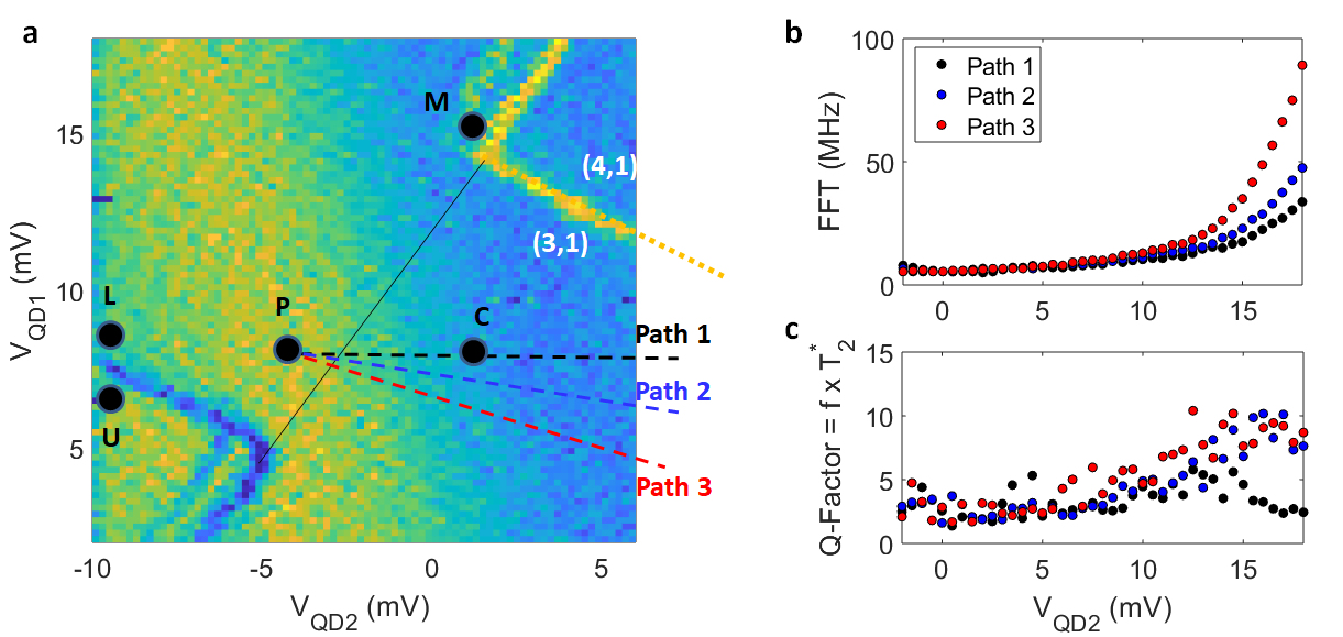
In Supplementary Fig. 13 we show the electrical control of the qubit frequency as a function of voltage applied to QD2 for QD-QD detunings along three separate paths. The different paths behave similarly, yet show differences in the plots. This suggests that while the vertical electric field influences the valley splitting of QD2, the voltage on both the QD1 and QD2 gates modify the the intervalley spin-orbit interaction.
.5 Valley splitting lever arm
We find that the ability to electrically modulate the intervalley SOC is consistent with control of the valley splitting, , through the applied gate voltages. Since the valley splitting plays an important role in dictating the magnetic field at which the polarized triplet state comes into resonance with the spin state , we can use the voltage dependence of the qubit evolution frequency in the vicinity of the hot spot to probe the variation of valley splitting with gate voltage.
To do this, we first fit to the qubit frequency versus magnetic field data of Fig. 2(b) for Device A and 12(e) for Device B, respectively. We then fix these fit parameters and assume a linear variation of the valley splitting as a function of deviation of the gate voltage from the operating point at which the preceding measurements were taken,
| (10) |
We show fits to the model parameters in Figs. 14 and 15, with parameter estimates in Table 1. The reported uncertainties correspond to 95% confidence intervals. Note that these measurements do not permit unambiguous determination of the valley-averaged -factor of Eq. 1, so for the purpose of these parameter estimates we enforce . The results shown in Table 1 are comparable with other results in silicon MOS QDs for valley splitting lever arms[15, 28, 18] and intervalley SOC strengths[15, 19, 69].
| Device A | Device B | |
|---|---|---|
| Intervalley SOC, () | ||
| Effective field gradient, () | ||
| Valley splitting, () | ||
| Valley splitting lever arm, () | ||
| Residual exchange, () |


.6 Impact of valley splitting
All silicon QD-based qubit architectures require sufficiently large valley splittings. Here, we briefly discuss a few of the implications of valley splitting on operating a singlet-triplet qubit or ensemble of singlet-triplet qubits using this hot-spot driven control scheme.
Since the applied magnetic field is assumed to be uniform across the sample, one requirement is that the hot spot must occur at similar magnetic field values for at least one dot of any given pair of quantum dots for all double dots in the ensemble. We have demonstrated here significant electrical control over the valley splitting, as indicated in Table 1. As long as the valley splittings for all relevant dots in the device are within the range of electrical tuning, in principle the hot spot driving scheme should be accessible. Given the measured valley splitting lever arm of 46 and 188 for the isotopically purified and natural Si devices, respectively, we can estimate roughly how much valley splitting uniformity would be required. The range of voltage values over which we routinely drive the qubit is on the order of 100 , which would correspond to a tunability of the valley splitting over a range of tens of . Hence, a uniformity of valley splitting within this range would presumably allow for hot spot operation for all qubits in the ensemble. Valley splitting has been shown to be tunable by a few hundred eV in other MOS QD device geometries [15, 28], which would further reduce the constraint on uniformity.