A Field-Enhanced Conduction-Cooled Superconducting Cavity for High-Repetition-Rate Ultrafast Electron Bunch Generation
Abstract
High-repetition-rate sources of bright electron bunches have a wide range of applications. They can directly be employed as probes in electron-scattering setups, or serve as a backbone for the generation of radiation over a broad range of the electromagnetic spectrum. This paper describes the development of a compact sub-Mega-electronvolt (sub-MeV) electron-source setup capable of operating at MHz repetition rates and forming sub-picosecond electron bunches with transverse emittance below 20 nm. The setup relies on a conduction-cooled superconducting single-cell resonator with its geometry altered to enhance the field at the surface of the emitter. The system is designed to accommodate cooling using a model a W at 4.2 K pulse tube cryogen-free cryocooler. Although we focus on the case of a photoemitted electron bunch, the scheme could be adapted to other emission mechanisms.
I introduction
Since its first application to particle accelerator decades ago, the superconducting radio-frequency (SRF) technology has steadily improved and enabled a new class of efficient accelerators with an increasing number of applications in fundamental science at national laboratories, e.g. in nuclear physics Leemann, Douglas, and Krafft 2001, and free-electron lasers Neil et al. 2000; Andruszkow et al. 2000. One of the main challenges limiting the dissemination of SRF-based accelerators is the complex infrastructure associated with the required cryogenic system (e.g. liquefaction and storing of Helium) necessary to maintain the SRF resonators below the critical temperature Kephart et al. 2015. Most recently, cryogen-free cooling techniques applied to SRF techniques have demonstrated the operation of superconducting resonators with high-quality factors and accelerating gradient MV/m Dhuley et al. 2020. Cryogen-free systems generally employ compact closed-cycle cryocoolers contacted to the cavity via thermal-conduction links Dhuley et al. 2019. Such an achievement could eventually enable the dissemination of compact efficient SRF based accelerator with an array of societal applications. Likewise, a conduction-cooled SRF resonator coupled with an electron-emission scheme could facilitate the generation of bright ultrafast electron beams at high-repetition rates that could be disseminated as a research tool or for societal applications.
This paper discusses the design of a conduction-cooled SRF electron source capable of generating ultra-fast electron bunch with quality on par with state-of-the-art setups. The proposed source is based on a simple modification of a single-cell resonant cavity and can operate at MHz repetition rates. It is expected to have an array of applications in industry Ciovati et al. 2018; Connelly et al. 2020, medicine Marx 2013 and ultra-fast electron scattering Weathersby et al. 2015.
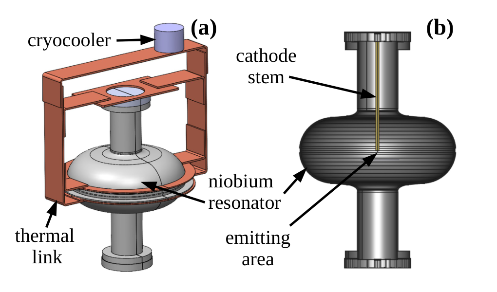
The proposed electron-source concept appears in Fig. 1: the system consists of a single-cell 650-MHz SRF cavity contacted to a cryocooler 4kc via a network of thermal-conduction links made of high-purity aluminum Dhuley et al. 2019. The setup is housed in a vacuum vessel that provides a thermally-insulating vacuum. The cavity, evacuated to ultra-high-vacuum pressure, is modified to incorporate a stem with a cathode (photoemission material) located at its extremity. The effect of the stem is twofold. First, it locally enhances the electric field at the emitting surface Daoud, Floettmann, and Dwayne Miller 2017 to support high-brightness electron emission given the favorable brightness scaling with the applied electric field at the cathode surface as where depends on the bunch initial aspect ratio Bazarov, Dunham, and Sinclair 2009; Filippetto et al. 2014. Second, the stem improves the transit time associated with the cavity as the shorter gap and higher electric field on the cathode surface significantly reduce the phase slippage between the emitted bunches and the oscillating electromagnetic fields.
Given the change in the electromagnetic-field distribution introduced by the stem, the magnetic fields on its surface result in significant ohmic losses which limit the resonator maximum accelerating field. The compromises between performance and engineering design of the resonator are examined in this paper.
II expected radiofrequency properties
In order to showcase the main advantages of the proposed concept we first investigate RF performances associated with the addition of a right-cylinder stem aligned along the cavity axis and with variable length. As expected, the stem impacts the resonant frequency of the cavity and leads to a significant enhancement of the electric-field amplitude at its extremity; see Fig. 2. Furthermore, the field can be further enhanced by reducing the stem radius from 5 to 3-mm. The simulations indicate that despite the modest dissipated-power ( W budget available), peak electric fields of MV/m can be attained at the cathode surface. These field values are higher than state-of-the-art DC guns with similar complexity Dunham et al. 2013 and comparable to state-of-the-art CW RF gun Sannibale 2014. The field-enhancement tapers off as the rod extremity reaches the cavity center (corresponding to a stem length mm) corresponding to the maximum attainable cathode-surface electric field. The corresponding relative frequency shift remains below %. Such a change is irrelevant in practice as the resonator is powered by a CW solid-state amplifier (SSA) which can be specified to accommodate a given frequency.
Consequently, to fully capitalize on the geometric enhancement, we focus on the case when the rod extremity is located at the center of the cavity. This configuration is generically denoted by ”FE”. The resulting field distribution is compared with the two other configurations in Fig. 3, full cavity with no stem ”FC” and half cell with no stem ”HC”. The relevant RF parameters including the unloaded resonator quality factor are directly evaluated with omega3p considering the properties of Nb at 5 K; see Tab. 1.
| parameter | unit | FC | HC | FE |
|---|---|---|---|---|
| MHz | 650 | 650 | 607 | |
| MV/m | 2.2 | 3.1 | 16.9 | |
| J | 0.123 | 0.123 | 0.080 | |
| 3.12 | 3.12 | 1.8 |
Assuming the same dissipated power, the HC geometry gives a maximum field a factor larger than the FC geometry. For the adopted stem geometry, the FE model produces maximum electric field MV/m. The associated magnetic-field pattern indicate substantially larger surface magnetic field of mT; see Fig. 2(f) which significantly increases the Ohmic losses. Finally, it should be pointed that for the simulated stored energy the CW power associated with the SSA is W. For the photoemission process considered latter in this paper, the beam power is W for a final beam energy keV, a single-bunch charge of fC with repetition frequency MHz.

III optimization of cathode stalk
The surface magnetic field on the introduced cathode stem yields a 40% reduction of the quality factor; see Tab. 1. Most importantly, large surface magnetic fields can impact the superconducting state of the cavity. This is mainly when large magnetic fields result in localized heating of the rod surface that results in its temperature surpassing the critical temperature . In the case of the cylindrical-rod geometry considered above, a thermal analysis using the field configuration display in Fig. 3(c) indicates that the temperature can locally attain values K. Consequently, we investigated possible approaches to reduce the equilibrium temperature to be below on the cavity wall and rod. A thermal model coupled to the RF simulations was developed. The thermal simulation was implemented in the finite-element-analysis program ansys:workbench 19.2 and considers the system depicted in Fig. 1(a) composed of the resonator, thermal links, and cryocooler. We assume the setup to be in thermal steady-state equilibrium where the dissipated power equates to the loading power of the cryocooler . A constant-temperature () boundary condition was applied to the contact surface between the cryocooler and thermal link. Additionally, several discretized heat-flux boundary conditions were applied to the surfaces of the cavity and cathode mount to model the dissipated power. The dissipated power per unit area on the surfaces exposed to the electromagnetic field given by
| (1) |
was numerically computed using the magnetic field distribution on the cavity internal surfaces simulated with omega3p and the surface resistance calculated with the algorithm srimp SRI which is based on quantum BCS theory of superconductors Halbritter 1970. Given the dependence of the surface resistance on the temperature an iterative method is used. First, the dissipated power is evaluated from the electromagnetic simulations with omega3p and used to compute the thermal heat flux in the thermal model for all the surfaces exposed to the electromagnetic field. The resulting temperature from the thermal simulation is then used to compute the dissipated power, taking into account the dependence , following the recursive relation (for ) The above process is repeated (for ) until convergence is attained. In addition to converging, it is also imperative that the maximum temperature (which is always at the rod tip) remains below the critical temperature . Therefore, it is convenient to define the tolerance parameter in terms of
| (2) |
with the condition . It should be noted that since the heat flows toward the cryocooler and the largest source of dissipated power occurs on the rod surface, the temperature reaches its maximum at the tip of the rod. The iteration process continues until becomes sufficiently small [typically ]. Figure 4 shows typical iterations for temperature distributions along the rod. In the case when the cavity is coated with the convergence is much faster compared with the case of pure niobium because the generated power is substantially lower for reasons explained below.
The convergence of the iteration process described above depends on dissipated power density, superconducting niobium thermal conductivity, and cryocooler operating temperature. The dissipated power density is directly related to the intensities of the electromagnetic fields that can be achieved inside the cavity and on stem geometry. The iterative procedure was repeated while altering the geometry of the cylindrical stem considered earlier. It was eventually found that a conically-shaped rod supports higher dissipation power while its surface remains at temperatures thus enabling higher electromagnetic fields inside the cavity.
Specifically, the devised geometry consists of a conical frustum rod with length 283 mm and radii of 5 mm and 20 mm at the tip and the base, respectively; see Fig. 5(b). To avoid spurious field emission from sharp edges, the rod extremity has a rounded edge with a curvature of 0.5 mm. Such a configuration allows for a dissipated power of 1.0 W considering a cryocooler operating at a constant temperature of K. For the case of pure niobium the temperature at rod tip is 6.5 K; see Fig. 5(a) and the peak axial electric and surface magnetic fields are respectively 18.2 MV/m and 18.3 mT (below mT for Nb Keckert et al. 2019). The corresponding cavity quality factor is estimated to be . Additionally, the conical frustum rod does not appear to significantly alter the fields downstream of the cathode-surface location compared to the cylindrical-rod geometry as inferred by comparing Fig. 5(b) and Fig. 3(c).

It is worth considering the case where the resonator shell is coated with a few thick layer of the Nb3Sn superconductor. The alloy Nb3Sn offers a lower surface resistance than pure Nb; see Fig. 4 (b). Typically, the ratio of surface resistance for these two materials at operating temperatures K is . Reproducing the previous thermal-electromagnetic simulations we found an Nb3Sn coated-resonator with the same conical shape as previously devised to support a similar maximum temperature (6.8 K is simulated at the conical-rod extremity) as the one obtained for the case of Nb. The corresponding attainable peak electric and surface magnetic fields are 65.2 MV/m and 65.0 mT, respectively and the estimated quality factor is . These values are significantly higher than the one obtained for pure niobium and in approximate agreement with the scaling described in Eq. 1. Such high field values have been demonstrated experimentally Posen et al. 2020. Moreover, Nb3Sn offers the possibility to operate at even lower dissipated power while still maintaining the required low temperature. For instance, scaling the dissipated power by a factor , i.e., from 1.0 W to 0.23 W would result in corresponding peak E and surface B fields of 31.1 MV/m and 31.0 mT ,respectively. operating at such low power would result in a final temperature of 3.9 K; see Fig.4 (a).
IV Beam-dynamics considerations
To fully assess the performance of the proposed configuration, we explore the generation of bright ultrafast electron beams via beam-dynamics simulations. We especially compare the performances associated with the proposed FE design with the beam parameters attainable in the commonly used HC configuration. The energy gain experienced by an electron propagating on axis of the two cavity configurations appears in Fig. 6(a) and confirms that despite the reduced accelerating gap, the FE geometry enables higher final energy (200 keV compared to 140 keV for the HC geometry). Figure 6(b) also compares the transverse electric field on the cathode surface. A drawback from the FE geometry is the strong radial component of the electric field (close to the cavity-axis the ) so that the conical-frustum rod results in a defocusing force at its tip. The radial field dependence on is more pronounced at radii approaching the edge ( mm) of the rod.
The beam-dynamics simulations were performed using the particle-in-cell (PIC) program impact-t Qiang et al. 2006. The program includes quasi-static space-charge effects using a mean-field algorithm and represents the electron bunch as an ensemble of macroparticles. We consider the case of photoemission where a laser pulse impinges the cathode to form an electron bunch. We assume the photo emitter to be deposited on the rod extremity. To quantify the brightness of the photo emitted electron bunch we introduce two metrics. The first one is the root-mean-square (RMS) transverse emittance defined as
| (3) |
where and are respectively the electronic mass and velocity of light, represents the horizontal position and momentum coordinates [the beam is taken to be cylindrical symmetric so that the emittance is the same for the horizontal and vertical phase spaces), and represents the statistical averaging over the macroparticle distribution. We also introduce the RMS bunch duration . The choice of these two figures of merit is rooted in the scaling of the bunch brightness as , where is the bunch charge. We specifically consider a beamline composed of the FE or HC resonator, a solenoidal magnetic lens followed by a drift space. The external fields (RF cavity and solenoidal lenses) are described by cylindrical-symmetric field maps. The solenoid lens controls the beam transverse emittance using a well-established compensation process Carlsten 1989.

We assume the electron bunch to retain a cylindrical-symmetry throughout its transport through the system given the symmetry of the external fields. The configuration was optimized using the deap multi-objective optimization framework Fortin et al. 2012 to seek configuration that minimize both and . The control variables include the photoemission-laser spot size and pulse duration, laser injection phase w.r.t. the resonator field, the solenoid-lens location. The bunch charge was set to fC (corresponding to electrons). We use the optimized laser parameters to generate an initial macroparticle distribution at the cathode surface with an emittance corresponding to a mean-transverse energy of meV. The results of the optimization are summarized in Fig. 7 where the Pareto fronts associated with the HC and FE geometries in the space and confirms the proposed FE geometry consistently produce a beam with a factor superior brightness compared to the HC geometry. The simulated beam parameters for the FE geometry are on par with those attained in state-of-the-art experiments at relativistic energies Maxson et al. 2017 while our setup is capable of operating in CW mode.
Figure 8 summarizes the evolution of the bunch duration and transverse emittances along the optimized beamline for accelerator settings giving nm for both the HE and FC configurations; see Tab. 2. The final bunch duration associated with the FE setup is one order of magnitude smaller than for the HC configuration.
| Parameter | FE | HC | unit |
| Laser pulse duration (rms) | 3.7 | 4.7 | |
| Laser spot size (rms) | 10.00 | 20.00 | |
| Launch phase | 127.00 | 93.6 | deg |
| Final beam energy | 270 | 178.2 | |
| Final transverse emittance (rms) | 15.0 | 16.0 | |
| Final bunch duration (rms) | 0.17 | 14.14 |

Finally, snapshots of the final transverse and longitudinal phase spaces appear in Fig. 9 for the two configurations. Due to the larger fields experienced by the bunch during the emission process in the FE configuration, the laser launch phase can be selected to form shorter bunches via the ballistic bunching without sacrificing the transverse emittance; see also Fig. 8(a). The resulting longitudinal phase space associated with the FE configuration is at a longitudinal waist with an RMS bunch duration of fs limited by third-order nonlinearities in the longitudinal phase space. This type of aberration could in principle be corrected following the technique discussed in Ref. Zeitler, Floettmann, and Grüner 2015.
V Conclusion
In conclusion, we demonstrated via numerical simulations that a single-cell elliptical resonator modified to enhance the field experienced by a bunch during emission can generate ultrafast electron bunches with superior transverse brightness than typically achieved in a standard half-cell configuration based on a similar elliptical geometry. The source design was optimized to be compatible with cryogen-free conduction cooling thereby resulting in a simple portable source. Nb3Sn coating offers a substantial increase in the peak electric field while giving the possibility to operate at lower temperatures thus minimizing ohmic losses due to its lower when compared to pure Nb.
It should be stressed that important technical challenges remain before the practical realization of the concept especially regarding the possible cavity-performance degradation from the photoemitting material. Likewise, a removable cathode assembly would ultimately be preferable and would require the design of a Choke filter. Nevertheless, the proposed setup could have interesting applications in ultrafast electron scattering experiments or could serve as an injector for optical-scale accelerator Peralta et al. 2013. Although the energy is currently limited to 200 keV, the addition of another full-cell resonator downstream of the FE resonator thermally supported by a dedicated cryocooler could produce beams with MeV’s energy. Ultimately, the proposed concept could be coupled with a field-emission source and open the path to MW average-power beams for a plethora of societal applications.
VI Acknowledgements
This work was supported by the US Department of Energy (DOE) under contract DE-SC0018367 with Northern Illinois University. Fermilab is managed by the Fermi Research Alliance, LLC for the DOE under contract number DE-AC02-07CH11359. We thank C. Ng (SLAC) and his team for providing access and guidance to the ace3p suite of programs. This research used resources of the National Energy Research Scientific Computing Center which is supported by the Office of Science of the U.S. DOE, Contract No. DE-AC02-05CH11231.
References
- Leemann, Douglas, and Krafft (2001) C. W. Leemann, D. R. Douglas, and G. A. Krafft, “The continuous electron beam accelerator facility: Cebaf at the jefferson laboratory,” Annual Review of Nuclear and Particle Science 51, 413–450 (2001), https://doi.org/10.1146/annurev.nucl.51.101701.132327 .
- Neil et al. (2000) G. R. Neil, C. L. Bohn, S. V. Benson, G. Biallas, D. Douglas, H. F. Dylla, R. Evans, J. Fugitt, A. Grippo, J. Gubeli, R. Hill, K. Jordan, R. Li, L. Merminga, P. Piot, J. Preble, M. Shinn, T. Siggins, R. Walker, and B. Yunn, “Sustained kilowatt lasing in a free-electron laser with same-cell energy recovery,” Phys. Rev. Lett. 84, 662–665 (2000).
- Andruszkow et al. (2000) J. Andruszkow, B. Aune, V. Ayvazyan, N. Baboi, R. Bakker, V. Balakin, D. Barni, A. Bazhan, M. Bernard, A. Bosotti, J. C. Bourdon, W. Brefeld, R. Brinkmann, S. Buhler, J.-P. Carneiro, M. Castellano, P. Castro, L. Catani, S. Chel, Y. Cho, S. Choroba, E. R. Colby, W. Decking, P. Den Hartog, M. Desmons, M. Dohlus, D. Edwards, H. T. Edwards, B. Faatz, J. Feldhaus, M. Ferrario, M. J. Fitch, K. Flöttmann, M. Fouaidy, A. Gamp, T. Garvey, C. Gerth, M. Geitz, E. Gluskin, V. Gretchko, U. Hahn, W. H. Hartung, D. Hubert, M. Hüning, R. Ischebek, M. Jablonka, J. M. Joly, M. Juillard, T. Junquera, P. Jurkiewicz, A. Kabel, J. Kahl, H. Kaiser, T. Kamps, V. V. Katelev, J. L. Kirchgessner, M. Körfer, L. Kravchuk, G. Kreps, J. Krzywinski, T. Lokajczyk, R. Lange, B. Leblond, M. Leenen, J. Lesrel, M. Liepe, A. Liero, T. Limberg, R. Lorenz, L. H. Hua, L. F. Hai, C. Magne, M. Maslov, G. Materlik, A. Matheisen, J. Menzel, P. Michelato, W.-D. Möller, A. Mosnier, U.-C. Müller, O. Napoly, A. Novokhatski, M. Omeich, H. S. Padamsee, C. Pagani, F. Peters, B. Petersen, P. Pierini, J. Pflüger, P. Piot, B. Phung Ngoc, L. Plucinski, D. Proch, K. Rehlich, S. Reiche, D. Reschke, I. Reyzl, J. Rosenzweig, J. Rossbach, S. Roth, E. L. Saldin, W. Sandner, Z. Sanok, H. Schlarb, G. Schmidt, P. Schmüser, J. R. Schneider, E. A. Schneidmiller, H.-J. Schreiber, S. Schreiber, P. Schütt, J. Sekutowicz, L. Serafini, D. Sertore, S. Setzer, S. Simrock, B. Sonntag, B. Sparr, F. Stephan, V. A. Sytchev, S. Tazzari, F. Tazzioli, M. Tigner, M. Timm, M. Tonutti, E. Trakhtenberg, R. Treusch, D. Trines, V. Verzilov, T. Vielitz, V. Vogel, G. v. Walter, R. Wanzenberg, T. Weiland, H. Weise, J. Weisend, M. Wendt, M. Werner, M. M. White, I. Will, S. Wolff, M. V. Yurkov, K. Zapfe, P. Zhogolev, and F. Zhou, “First observation of self-amplified spontaneous emission in a free-electron laser at 109 nm wavelength,” Phys. Rev. Lett. 85, 3825–3829 (2000).
- Kephart et al. (2015) R. Kephart et al., “Srf compact accelerator for industry and society,” in Proceedings of SRF2015, Whistler, BC, Canada (2015) pp. 1467–1469.
- Dhuley et al. (2020) R. Dhuley, S. Posen, M. Geelhoed, O. Prokofiev, and J. C. T. Thangaraj, “First demonstration of a cryocooler conduction cooled superconducting radiofrequency cavity operating at practical cw accelerating gradients,” Superconductor Science and Technology (2020).
- Dhuley et al. (2019) R. C. Dhuley, R. Kostin, O. Prokofiev, M. I. Geelhoed, T. H. Nicol, S. Posen, J. C. T. Thangaraj, T. K. Kroc, and R. D. Kephart, “Thermal link design for conduction cooling of srf cavities using cryocoolers,” IEEE Transactions on Applied Superconductivity 29, 1–5 (2019).
- Ciovati et al. (2018) G. Ciovati, J. Anderson, B. Coriton, J. Guo, F. Hannon, L. Holland, M. LeSher, F. Marhauser, J. Rathke, R. Rimmer, T. Schultheiss, and V. Vylet, “Design of a cw, low-energy, high-power superconducting linac for environmental applications,” Phys. Rev. Accel. Beams 21, 091601 (2018).
- Connelly et al. (2020) J. M. Connelly, J. R. Harris, R. B. Miller, J. W. Lewellen, F. L. Krawczyk, N. T. Myers, and W. E. Sommars, “Application of a radial radio-frequency electron gun to waste treatment,” Radiation Physics and Chemistry 166, 108440 (2020).
- Marx (2013) V. Marx, “Brain mapping in high resolution,” Nature 503, 147 (2013).
- Weathersby et al. (2015) S. P. Weathersby, G. Brown, M. Centurion, T. F. Chase, R. Coffee, J. Corbett, J. P. Eichner, J. C. Frisch, A. R. Fry, M. Gühr, N. Hartmann, C. Hast, R. Hettel, R. K. Jobe, E. N. Jongewaard, J. R. Lewandowski, R. K. Li, A. M. Lindenberg, I. Makasyuk, J. E. May, D. McCormick, M. N. Nguyen, A. H. Reid, X. Shen, K. Sokolowski-Tinten, T. Vecchione, S. L. Vetter, J. Wu, J. Yang, H. A. Dürr, and X. J. Wang, “Mega-electron-volt ultrafast electron diffraction at slac national accelerator laboratory,” Review of Scientific Instruments 86, 073702 (2015), https://doi.org/10.1063/1.4926994 .
- (11) “Cryomech: 4k pt420 cryocooler,” https://www.cryomech.com/products/pt420/, accessed: 2020-12-17.
- Daoud, Floettmann, and Dwayne Miller (2017) H. Daoud, K. Floettmann, and R. J. Dwayne Miller, “Compression of high-density 0.16 pC electron bunches through high field gradients for ultrafast single shot electron diffraction: The compact rf gun,” Structural Dynamics 4, 044016 (2017), https://doi.org/10.1063/1.4979970 .
- Bazarov, Dunham, and Sinclair (2009) I. V. Bazarov, B. M. Dunham, and C. K. Sinclair, “Maximum achievable beam brightness from photoinjectors,” Phys. Rev. Lett. 102, 104801 (2009).
- Filippetto et al. (2014) D. Filippetto, P. Musumeci, M. Zolotorev, and G. Stupakov, “Maximum current density and beam brightness achievable by laser-driven electron sources,” Phys. Rev. ST Accel. Beams 17, 024201 (2014).
- Dunham et al. (2013) B. Dunham, J. Barley, A. Bartnik, I. Bazarov, L. Cultrera, J. Dobbins, G. Hoffstaetter, B. Johnson, R. Kaplan, S. Karkare, V. Kostroun, Y. Li, M. Liepe, X. Liu, F. Loehl, J. Maxson, P. Quigley, J. Reilly, D. Rice, D. Sabol, E. Smith, K. Smolenski, M. Tigner, V. Vesherevich, D. Widger, and Z. Zhao, “Record high-average current from a high-brightness photoinjector,” Applied Physics Letters 102, 034105 (2013), https://doi.org/10.1063/1.4789395 .
- Sannibale (2014) F. Sannibale, “High-brightness high-duty cycle electron injectors,” Nuclear Instruments and Methods in Physics Research Section A: Accelerators, Spectrometers, Detectors and Associated Equipment 740, 10 – 16 (2014), proceedings of the first European Advanced Accelerator Concepts Workshop 2013.
- (17) “Srimp,” Accessed April. 6, 2020.
- Halbritter (1970) J. Halbritter, “Comparison between measured and calculatedrf losses in the superconducting state,” Zeitschrift für Physik 238, 466–476 (1970).
- Keckert et al. (2019) S. Keckert, T. Junginger, T. Buck, D. Hall, P. Kolb, O. Kugeler, R. Laxdal, M. Liepe, S. Posen, T. Prokscha, Z. Salman, A. Suter, and J. Knobloch, “Critical fields of nb3sn prepared for superconducting cavities,” Superconductor Science and Technology 32, 075004 (2019).
- Posen et al. (2020) S. Posen, B. Tennis, J. Lee, O. Melnychuk, Y. Pischalnikov, D. Sergatskov, and D. Seidman, “Nb3sn at fermilab: Exploring performance,” in Proceedings of 19th International Conference on RF Superconductivity (Dresden, Germany, 2019) pp (2020) pp. 820–824.
- Qiang et al. (2006) J. Qiang, S. Lidia, R. D. Ryne, and C. Limborg-Deprey, “Three-dimensional quasistatic model for high brightness beam dynamics simulation,” Phys. Rev. ST Accel. Beams 9, 044204 (2006).
- Carlsten (1989) B. Carlsten, “New photoelectric injector design for the los alamos national laboratory xuv fel accelerator,” Nuclear Instruments and Methods in Physics Research Section A: Accelerators, Spectrometers, Detectors and Associated Equipment 285, 313 – 319 (1989).
- Fortin et al. (2012) F.-A. Fortin, F.-M. De Rainville, M.-A. Gardner, M. Parizeau, and C. Gagné, “DEAP: Evolutionary algorithms made easy,” Journal of Machine Learning Research 13, 2171–2175 (2012).
- Maxson et al. (2017) J. Maxson, D. Cesar, G. Calmasini, A. Ody, P. Musumeci, and D. Alesini, “Direct measurement of sub-10 fs relativistic electron beams with ultralow emittance,” Phys. Rev. Lett. 118, 154802 (2017).
- Zeitler, Floettmann, and Grüner (2015) B. Zeitler, K. Floettmann, and F. Grüner, “Linearization of the longitudinal phase space without higher harmonic field,” Phys. Rev. ST Accel. Beams 18, 120102 (2015).
- Peralta et al. (2013) E. A. Peralta, K. Soong, R. J. England, E. R. Colby, Z. Wu, B. Montazeri, C. McGuinness, J. McNeur, K. J. Leedle, D. Walz, E. B. Sozer, B. Cowan, B. Schwartz, G. Travish, and R. L. Byer, “Demonstration of electron acceleration in a laser-driven dielectric microstructure,” Nature 503, 91–94 (”2013”).