Secure Wireless Communication in RIS-Aided MISO System with Hardware Impairments
Abstract
In practice, residual transceiver hardware impairments inevitably lead to distortion noise which causes the performance loss. In this paper, we study the robust transmission design for a reconfigurable intelligent surface (RIS)-aided secure communication system in the presence of transceiver hardware impairments. We aim for maximizing the secrecy rate while ensuring the transmit power constraint on the active beamforming at the base station and the unit-modulus constraint on the passive beamforming at the RIS. To address this problem, we adopt the alternate optimization method to iteratively optimize one set of variables while keeping the other set fixed. Specifically, the successive convex approximation (SCA) method is used to solve the active beamforming optimization subproblem, while the passive beamforming is obtained by using the semidefinite program (SDP) method. Numerical results illustrate that the proposed transmission design scheme is more robust to the hardware impairments than the conventional non-robust scheme that ignores the impact of the hardware impairments.
Index Terms:
Intelligent reflecting surface (IRS), reconfigurable intelligent surface (RIS), hardware Impairments, secure communication.I Introduction
Physical layer security issue has become a critical concern in current and future wireless networks [1]. Fortunately, reconfigurable intelligent surface (RIS) is promising for its application in physical layer security owing to the fact that the RIS can reconfigure electromagnetic propagation environment for spectral and energy efficiency enhancement in various applications [2, 3, 4, 5, 6]. In particular, an RIS, which is the key enabler to realize the vision of smart radio environments [7, 8], is an inexpensive adaptive (smart) thin panel that is composed of a number of nearly-passive reflecting elements with controllable phase shifts. RIS is capable of reconfiguring the reflected signal constructively for the signal power enhancement at the legitimate users or destructively for avoiding the information leakage to the eavesdroppers. The authors in [9] derived a closed-form solution to the secrecy rate maximization problem for an RIS-aided single-user wireless communication system with one eavesdropper. The extension to the more general case with multiple eavesdroppers and multiple legitimate users was studied in [10]. Furthermore, Yu et.al. [11] investigated the robust transmission design for an RIS-aided multiuser secure communication system by considering the imperfect channel state information (CSI). Then, an RIS-aided secure system was studied in [12], where the artificial noise was used to enhance the security performance.
However, all the above-mentioned contributions on RIS-aided secure communications assume the perfect hardware at the legitimate users, which is too ideal in practice. The practical radio-frequency (RF) components suffer from inevitable hardware impairments, including phase noise, quantization errors, amplification noise, and nonlinearities [13]. Both analytical and experimental results verify that the distortion noise caused by the residual transceiver hardware impairments can be modeled as additive Gaussian distribution, whose variance is proportional to the signal power [13]. Recent works have investigated the impact of hardware impairments on RIS-aided systems [14, 15, 16]. A closed-form expression for the outage probability in an RIS-aided system was derived in [14], which revealed the fact that the hardware imperfection has prominent impact on the achievable spectral efficiency. Robust beamforming design was proposed in [15] to maximize the received signal-to-noise ratio (SNR) for an RIS-aided single-user multiple-input single-output (MISO) system by considering the transceiver hardware impairments. Furthermore, both uplink channel estimation and downlink transceiver design were investigated in a single-user MISO system [16] by considering the RF impairments at the BS and phase noise at the IRS.
To the best of our knowledge, the robust transmission design for an RIS-aided secure wireless communication system in the presence of transceiver hardware impairments has not been studied. To enhance the secrecy rate of the system, we jointly design the active beamforming at the BS and the passive beamforming at the RIS by considering the hardware imperfection. The formulated optimization problem is solved by resorting to alternating optimization, successive convex approximation, and semidefinite relaxation. The simulation results demonstrate the performance advantages of the proposed robust design scheme over the benchmark schemes.
Notations: Most of the notations in this paper are standard. The symbol denotes the modulus of a complex scalar. is a diagonal matrix with the entries of on its main diagonal. is a diagonal matrix whose diagonal entries are the diagonal elements of matrix . means that is positive semidefinite. Additionally, the symbol denotes complex field and represents real field.
II System Model
II-A Signal Transmission Model
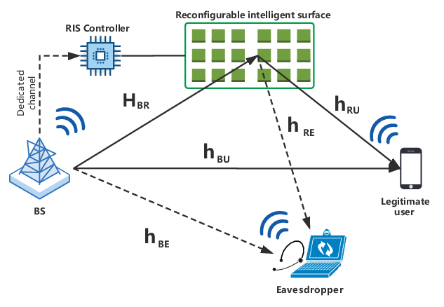
Consider the downlink of an RIS-aided secure communication system where a single-antenna eavesdropper intends to eavesdrop the confidential signals sent by the BS to a single-antenna legitimate user, as shown in Fig. 111 1 The proposed algorithm in this work for the single-user case can be directly applied to multi-user cases, including multiple legitimate users or multiple eavesdroppers. The BS is equipped with active antennas. An RIS equipped with programmable phase shifters is deployed in the network to improve the physical layer security. Different from the existing works, we consider the residual hardware impairments at the BS and the legitimate user. Therefore, the signal transmitted by the BS is given by
| (1) |
where denotes the confidential independent Gaussian data symbol and follows , and is the corresponding beamforming vector. is the independent Gaussian transmit distortion noise and the power of the distortion noise at each antenna is proportional to its transmit signal power, i.e., , where is the ratio of transmit distorted noise power to transmit signal power. This model has been widely used in the existing literature [13, 14, 15, 16] and is supported by theoretical investigations and measurements [13] to accurately model the joint effect of imperfect components in RF chains of practical multiple-antenna systems.
The channels between the BS and the RIS, the BS and the legitimate user, and the RIS and the legitimate user are denoted by , and , respectively. Then, the downlink received signal at the legitimate user can be expressed as
| (2) |
where . represents the additive white Gaussian noise (AWGN) at the legitimate user with noise variance . , where is the reflection coefficient on the -th reflecting element of the RIS. is an independent zero-mean Gaussian distortion noise at the legitimate user, which follows the distribution of , where is the ratio of distorted noise power to undistorted received signal power [17].
Similar to [18], since the BS cannot acquire the full knowledge about the eavesdropper, we consider the worst-case that the eavesdropper has a high-quality hardware such that there is no residual hardware impairments. Thus, the signal received by the eavesdropper can be modeled as
| (3) |
where is the AWGN following the distribution of . and are the channels of the BS-eavesdropper and the RIS-eavesdropper links, respectively. In this work, we assume that the BS perfectly knows all the CSI in the entire network.
The secrecy rate of the system in can be expressed as
| (4) |
where .
is the rate of the legitimate user and is written as
| (5) |
where is the equivalent reflection coefficient vector, is the equivalent channel, and is the sum power of distortion noise and thermal noise.
is the rate of the eavesdropper and is expressed as
| (6) |
where is the equivalent channel, and is the sum power of distortion noise and thermal noise.
II-B Problem Formulation
In this work, we propose to maximize the secrecy rate given in (4) by jointly optimizing the beamforming vector at the BS and the passive beamforming at the RIS. The problem is formulated as
| (7a) | ||||
| (7b) | ||||
| (7c) | ||||
where (7b) is the transmit power constraint with the maximum transmit power at the BS, and (7c) imposes a unit modulus on each entry in with the set . We remark that the optimal value of Problem (7) is always non-negative. If , we can set such that the value of the objective function is equal to zero.
Problem (7) is challenging to solve due to the non-concave objective function and the non-convex constraint (7c). Furthermore, in contrast to [19] that a closed-form solution was derived for , it is not straightforward to obtain a closed-form solution for in Problem (7) due to the fact that the distortion noise introduced by the hardware impairments aggregate the complexity of the secrecy rate expression.
III Algorithm design for secure wireless communications
In this section, we adopt the alternating optimization (AO) method to address the coupling of the beamforming vector at the BS and the reflection beamforming at the RIS in Problem (7). Specifically, we alternately update and while fixing the other variable.
First, due to (5) and (6), we introduce auxiliary variables , which satisfy
| (8a) | ||||
| (8b) | ||||
| (8c) | ||||
| (8d) | ||||
such that and . With (8), Problem (7) is reformulated as
| (9a) | ||||
| (9b) | ||||
By using contradiction method, it can be readily proved that constraints in (8) hold with equality at the optimum. Hence, Problem (9) is equivalent to Problem (7).
III-A Optimize with fixed
When is given, we further introduce auxiliary variables such that non-convex constraints (8) are respectively equivalent to
| (10a) | ||||
| (10b) | ||||
| (10c) | ||||
| (10d) | ||||
and
| (11a) | ||||
| (11b) | ||||
| (11c) | ||||
| (11d) | ||||
It is observed from (10) and (11) that constraints (10a), (10d), (11b), and (11c) are convex, while constraints (10b), (10c), (11a), and (11d) are concave. According to [20], the SCA can be used to address those concave constraints. In particular, by adopting the first-order Taylor approximation and the equality , we have the following equivalent constraints
| (12a) | ||||
| (12b) | ||||
| (12c) | ||||
| (12d) | ||||
where and . , , and are the solutions obtained at the -th iteration.
Finally, the subproblem for solving is formulated as
| (13a) | ||||
| (13b) | ||||
Problem (13) is an SOCP and can be solved by using the CVX tool.
III-B Optimize with fixed
In order to tackle the non-convex unit-modulus constraint , we adopt the semidefinite relaxation (SDR) technique to update . In particular, by defining a new variable , constraint is replaced by . Furthermore, with fixed and new auxiliary variables , non-convex constraints (8a) and (8b) are equivalent to
| (14a) | ||||
| (14b) | ||||
| (14c) | ||||
| (14d) | ||||
where and . The non-convex constraints (8c) and (8d) are equivalent to
| (15a) | ||||
| (15b) | ||||
| (15c) | ||||
| (15d) | ||||
where and . In (14) and (15), the only non-convex constraints (14b) and (15a) can be approximated by using the first-order Taylor approximation as
| (16a) | ||||
| (16b) | ||||
where and are the solutions obtained at the -th iteration.
Finally, the relaxed subproblem of Problem (9) is formulated as
| (17a) | ||||
| (17b) | ||||
| (17c) | ||||
Problem (17) is further relaxed to a convex SDP by applying SDR method and then solved by the CVX tools. The suboptimal solution , which maximizes the objective value of Problem (7), can be obtained from the optimal by using Gaussian randomization techniques. Then, is projected onto the constraint set as , where , denotes the angle of , and denotes the -th entry of vector . Please note that the suboptimal solution generated by the SDR method cannot guarantee that the objective value of Problem (7) in the -th iteration is no smaller than that in the previous iteration. Therefore, in order to ensure the non-decreasing objective value sequence generated in each iteration, we adopt the following update
| (18) |
Note that when , we still have and the iteration process does not terminate until convergence. The reason is that the optimal of the next iteration is obtained based on and .
III-C Algorithm Analysis
Convergence analysis
Firstly, we state that the objective value sequence generated in each iteration in the AO algorithm is non-decreasing. In particular, it follows that
The above (a) is due to the update in (18), and (b) follows from the globally optimal solution of Problem (13) for a given . Moreover, has a finite upper bound due to the bounded transmit power constraint. Therefore, the AO algorithm is guaranteed to converge.
Complexity analysis
IV Numerical results and discussions
In this section, the numerical results are provided to evaluate the performance of the proposed algorithm for an RIS-aided system with hardware impairments. The BS and the RIS are located at (0 m, 0 m) and (50 m, 0 m), respectively. Both legitimate user and eavesdropper lie in a horizontal line which is parallel to the BS-RIS path, which means the coordinates of legitimate user and eavesdropper are (50 m, 2 m) and (45 m, 2 m), respectively. We set and dBm. The large-scale path loss is dB, where is the path loss exponent and is the link length in meters. The path loss exponent of the RIS related channels is set to and that of the direct BS-user and BS-eavesdropper channels is set to . The small-scale fading follows a Rician distribution with a Ricean factor of 10 for the RIS related channels and a Ricean factor of 0 for the direct channels. The line-of-sight (LoS) components are defined by the product of the steering vectors of the transmitter and receiver and the non-LoS components are drawn from a Rayleigh fading. The proposed scheme and the benchmark schemes are listed as: 1) “RIS-robust”, the proposed robust beamforming design compensating for the hardware impairments in an RIS-aided system; 2) “NonRIS-robust”, a robust beamforming design compensating for the hardware impairments in a conventional system without RIS; 3) “RIS-nonrobust”, naive beamforming design ignoring the hardware impairments in an RIS-aided system; 4) “NonRIS-nonrobust”, naive beamforming design ignoring the hardware impairments in a conventional system without RIS.
Fig. 2 investigates the secrecy rate of different schemes as a function of the maximum transmit power at the BS when . Fig. 2 shows that the secrecy rate tends to be stable with the increase of . This is because the distortion noise caused by hardware impairments is proportional to the transceiver signal power, so there is an upper bound for the secrecy rate as a function of the maximum transmit power. It is interesting to find that the robust beamforming design in traditional systems without RIS is not effective in compensating for the performance loss caused by the hardware impairments. However, the robust design is more effective in RIS-aided secure systems. These observations reveal the importance of the robust design for RIS-aided secure systems by considering the hardware impact.
Fig. 3 illustrates the impact of the number of the reflecting elements on the system performance when dBm. Firstly, the increase of RIS’s size can enhance the secrecy rate, but this performance gain decreases when the level of the hardware impairments (i.e., and ) increases. Furthermore, by comparing the systems with and the systems with , the hardware impairments on legitimate user has a greater negative impact on the secrecy rate than that of the hardware impairments on the BS. This is because the proportion of the receive distortion noise power in total received noise is much larger than the transmit distortion noise power.

V Conclusions
In this work, we have improved the performance of the secrecy communication system in the presence of transceiver hardware impairments by employing an RIS and designing robust beamforming. The secrecy rate of the system was maximized by the joint optimization of the active beamforming vector at the BS and the passive beamforming at the RIS when the distortion noise caused by the hardware impairments was taken into account. The two variables were updated alternately by solving two approximate subproblems as the form of SOCP and SDP, respectively. Our simulation results have demonstrated the performance advantage of the proposed beamforming design.
References
- [1] N. Yang, L. Wang, G. Geraci, M. Elkashlan, J. Yuan, , and M. Di Renzo, “Safeguarding 5G wireless communication networks using physical layer security,” IEEE Commun. Mag., vol. 53, no. 4, pp. 20–27, Apr. 2015.
- [2] C. Pan, H. Ren, K. Wang, M. Elkashlan, A. Nallanathan, J. Wang, and L. Hanzo, “Intelligent reflecting surface aided MIMO broadcasting for simultaneous wireless information and power transfer,” IEEE J. Sel. Areas Commun., vol. 38, no. 8, pp. 1719–1734, Aug. 2020.
- [3] C. Pan, H. Ren, K. Wang, W. Xu, M. Elkashlan, A. Nallanathan, and L. Hanzo, “Multicell MIMO communications relying on intelligent reflecting surfaces,” IEEE Trans. Wireless Commun., vol. 19, no. 8, pp. 5218–5233, Aug. 2020.
- [4] X. Yu, D. Xu, D. W. K. Ng, and R. Schober, “IRS-assisted green communication systems: Provable convergence and robust optimization,” 2020. [Online]. Available: https://arxiv.org/abs/2011.06484
- [5] B. Ning, Z. Chen, W. Chen, and J. Fang, “Beamforming optimization for intelligent reflecting surface assisted MIMO: A sum-path-gain maximization approach,” IEEE Wireless Commun. Lett., vol. 9, no. 7, pp. 1105–1109, Jul. 2020.
- [6] D. Xu, X. Yu, Y. Sun, D. W. K. Ng, and R. Schober, “Resource allocation for secure IRS-assisted multiuser MISO systems,” in 2019 IEEE Globecom Workshops (GC Wkshps), pp. 1–6.
- [7] M. Di Renzo et al., “Smart radio environments empowered by reconfigurable intelligent surfaces: How it works, state of research, and road ahead,” IEEE J. Sel. Areas Commun., vol. 38, no. 11, pp. 2450–2525, Nov. 2020.
- [8] C. Pan, H. Ren, K. Wang et al., “Reconfigurable intelligent surface for 6G and beyond: Motivations, principles, applications, and research directions,” Nov. 2020. [Online]. Available: https://arxiv.org/abs/2011.04300
- [9] M. Cui, G. Zhang, and R. Zhang, “Secure wireless communication via intelligent reflecting surface,” IEEE Wireless Commun. Lett., vol. 8, no. 5, pp. 1410–1414, Oct. 2019.
- [10] J. Chen, Y. C. Liang, Y. Pei, and H. Guo, “Intelligent reflecting surface: A programmable wireless environment for physical layer security,” IEEE Access, vol. 7, pp. 82 599–82 612, Jun. 2019.
- [11] X. Yu, D. Xu, Y. Sun, D. W. K. Ng, and R. Schober, “Robust and secure wireless communications via intelligent reflecting surfaces,” IEEE J. Sel. Areas Commun., vol. 38, no. 11, pp. 2637–2652, Nov. 2020.
- [12] S. Hong, C. Pan, H. Ren, K. Wang, and A. Nallanathan, “Artificial-noise-aided secure MIMO wireless communications via intelligent reflecting surface,” IEEE Trans. Commun., vol. 68, no. 12, pp. 7851–7866, Dec. 2020.
- [13] E. Bjärnson, J. Hoydis, M. Kountouris, and M. Debbah, “Massive MIMO systems with non-ideal hardware: Energy efficiency, estimation, and capacity limits,” IEEE Trans. Inf. Theory, vol. 60, no. 11, pp. 7112–7139, 2014.
- [14] A. A. Boulogeorgos and A. Alexiou, “How much do hardware imperfections affect the performance of reconfigurable intelligent surface-assisted systems?” IEEE Open J. Commun. Society, vol. 1, pp. 1185–1195, 2020.
- [15] H. Shen, W. Xu, S. Gong, C. Zhao, and D. W. K. Ng, “Beamforming optimization for IRS-aided communications with transceiver hardware impairments,” IEEE Trans. Commun., pp. 1–1, 2020.
- [16] Y. Liu, E. Liu, R. Wang, and Y. Geng, “Beamforming designs and performance evaluations for intelligent reflecting surface enhanced wireless communication system with hardware impairments,” 2020. [Online]. Available: https://arxiv.org/abs/2006.00664
- [17] B. P. Day, A. R. Margetts, D. W. Bliss, and P. Schniter, “Full-duplex MIMO relaying: Achievable rates under limited dynamic range,” IEEE J. Sel. Areas Commun., vol. 30, no. 8, pp. 1541–1553, Sept. 2012.
- [18] J. Zhu, D. W. K. Ng, N. Wang, R. Schober, and V. K. Bhargava, “Analysis and design of secure massive MIMO systems in the presence of hardware impairments,” IEEE Trans. Wireless Commun., vol. 16, no. 3, pp. 2001–2016, Mar. 2017.
- [19] H. Shen, W. Xu, S. Gong, Z. He, and C. Zhao, “Secrecy rate maximization for intelligent reflecting surface assisted multi-antenna communications,” IEEE Commun. Lett., vol. 23, no. 9, pp. 1488–1492, Sept. 2019.
- [20] S. Boyd and L. Vandenberghe, Convex optimization. Cambridge Univ. Press, 2004.
- [21] A. Ben-Tal and A. Nemirovski, (Lectures on modern convex optimization: Analysis, algorithms, and engineering applications). Philadelphia, PA, USA: SIAM. MPSSIAM Ser. Optim., 2001.