Kelvin’s Chirality of Optical Beams
Abstract
Geometrical chirality is a property of objects that describes three-dimensional mirror-symmetry violation and therefore it requires a non-vanishing spatial extent. In contrary, optical chirality describes only the local handedness of electromagnetic fields and neglects the spatial geometrical structure of optical beams. In this manuscript, we put forward the physical significance of geometrical chirality of spatial structure of optical beams, which we term Kelvin’s chirality. Further, we report on an experiment revealing the coupling of Kelvin’s chirality to optical chirality upon transmission of a focused beam through a planar medium. Our work emphasizes the importance of Kelvin’s chirality in all light-matter interaction experiments involving structured light beams with spatially inhomogeneous phase and polarization distributions.
I Introduction
Since its first definition by Lord Kelvin in 1893 Sir William Thomson Lord
Kelvin 1894, the term “chiral” has found its use across the fields of physics, mathematics, chemistry and biology. Chirality describes mirror-symmetry violation — if an object cannot be superimposed with its own mirror image by means of rotations and translations, it is termed chiral Sir William Thomson Lord
Kelvin 1894; Barron 1986a; Barron 1986b; Barron 2012. Consequently, geometrical chirality is inherently a non-local three-dimensional (3D) structural property of objects that requires a non-vanishing spatial extent Buda and Mislow 1992; Buda et al. 1992; Rassat and Fowler 2004; Fowler 2005; Efrati and Irvine 2014; Fernandez-Corbaton et al. 2016; Gutsche et al. 2020.
On the other hand, optical chirality is a bit less tangible. Using parity inversion transform (a point reflection) Sir William Thomson Lord
Kelvin 1894; Barron 1986a; Barron 1986b; Barron 2012 to define optical chirality allows electromagnetic beams to be chiral at specific points in space. The common definition of optical chirality as Tang and Cohen 2010; Bliokh and Nori 2011; Coles and Andrews 2012; Andrews and Coles 2012; Bliokh et al. 2014; Nieto-Vesperinas 2017a; Cameron Robert P. et al. 2017; Crimin et al. 2019; Poulikakos et al. 2019; Mackinnon 2019, where E and H refer to the electric and magnetic field vectors, respectively, is in perfect agreement with this.
Optical chirality plays a crucial role in chiral light-matter interactions Tang and Cohen 2010; Valev et al. 2013; Bliokh et al. 2014; Bradshaw et al. 2015; Lodahl et al. 2017. Tools such as circular dichroism spectroscopy are widely used for distinguishing molecular enantiomers, studying proteins’ structure and measuring the composition of materials Woody 1995; Barron 2004.
In all these scenarios, chiroptical phenomena are used to determine whether the interacting matter features geometrical chirality originating from its spatial extent.
However, polarization and phase distributions of optical beams can exhibit fascinating topological features in 3D space as well. These include knotted and linked polarization and phase singularities Berry and Dennis 2001; Leach et al. 2004; Larocque et al. 2018 and even polarization Möbius strips Bauer et al. 2015. Some of these peculiar field topologies are asymmetric upon parity transformation, rendering the optical beams geometrically chiral. Nonetheless, these beams do not necessarily also exhibit optical chirality. Since the definition of optical chirality only refers to a local arrangement of E and H, it fails to describe any form of chirality originating from the spatial extent of the beams. This geometrical chirality of the spatial polarization- and phase-structure of optical beams (hereinafter referred to as Kelvin’s chirality or ) may be directly involved in chiral light-matter interaction. Indeed, the corkscrew wavefronts of linearly polarized Laguerre-Gaussian beams readily engage in chiral light-matter interactions Toyoda et al. 2012; Wong et al. 2012; Gorodetski et al. 2013; Forbes and Andrews 2018; Nechayev et al. 2019a; Woźniak et al. 2019; Forbes and Andrews 2019a; Forbes and Andrews 2019b. Also the polarization structure of vector beams with can produce circularly polarized light (CPL) upon scattering by achiral particles Eismann et al. 2018; Nechayev and Banzer 2019. Kelvin’s chirality therefore represents an electromagnetic equivalent of geometrical chirality and refers to a certain chiral arrangement of electromagnetic fields in 3D space. It complies with the point-reflection geometrical non-local definition of chirality, but it can not be described involving optical chirality .
To explore the phenomenon of Kelvin’s chirality, we construct an experiment, where a normally incident polarization-structured cylindrically symmetric beam with and is focused and transmitted through a planar stratified medium. Surprisingly, we observe CPL in transmission () with its handedness being dependent on the incident . We elucidate our results using a simple geometrical model, generalized Fresnel coefficients of the layered sample, and helicity conservation laws Fernandez-Corbaton et al. 2012; Cameron et al. 2012; Cameron Robert P. et al. 2017; Barnett et al. 2012; Fernandez-Corbaton et al. 2013; Bliokh et al. 2013; Nieto-Vesperinas 2015; Nieto-Vesperinas 2017a; Nieto-Vesperinas 2017b; Fernandez-Corbaton and Rockstuhl 2017; Crimin et al. 2019; Poulikakos et al. 2019; Mackinnon 2019. Our work calls for a careful evaluation of Kelvin’s chirality as a crucial component of all light-matter interaction experiments that involve light beams with spatially inhomogeneous phase or polarization distributions.
II Theory

We investigate a system of two dry aplanatic microscope objectives (MO1 and MO2) in confocal alignment, as sketched in Figure 1, with an incident monochromatic beam propagating along the -axis. Focusing by an aplanatic MO1 converts the spatial coordinates in the back focal plane (BFP1) of MO1 to the angular coordinates of the focused beam via , , where is the focal length, is the wavenumber and is the wavelength Novotny and Hecht 2012. Collimation by MO2 induces a reverse transformation such that in BFP2 we obtain . To describe the evolution of polarization pattern, we decompose the incident beam into radial and azimuthal polarization components, which correspond to the transverse magnetic (TM or ) and transverse electric (TE or ) polarization components of the focused beam, respectively. Reference Novotny and Hecht 2012 describes the process in detail.
Consider now a spirally polarized incident vector beam (see Fig. 1), which is an in- or -out-of-phase superposition of a radially and an azimuthally polarized mode Zhan and Leger 2002; Eismann et al. 2018; Nechayev and Banzer 2019; Nechayev et al. 2020. The electric field in the BFP1, which we assume to coincide with the beam’s waist position (), can be written as:
| (1) |
where , with being the beam waist, is a constant, is the radial cylindrical coordinate, and are the radial and axial unit vectors, respectively, and , corresponding to an in- or -out-of-phase superposition. We note that parity transformation applied to the beam in Eq. (1) inverses the direction of the spiral polarization Nechayev and Banzer 2019. Therefore, without assigning an exact value to , we can argue that the beam in Eq. (1) possesses a non-zero Kelvin’s chirality and that a pair beams with constitute a pair of chiral enantiomers, which implies that . At the same time, such beams feature zero optical chirality , which in the paraxial regime can be expressed as the third Stokes parameter Tang and Cohen 2010; Bliokh and Nori 2011; Coles and Andrews 2012; Andrews and Coles 2012; Nieto-Vesperinas 2017a; Cameron Robert P. et al. 2017; Crimin et al. 2019; Poulikakos et al. 2019; Mackinnon 2019:
| (2) |
We introduce a planar layered structure between the MOs (Fig. 1) positioned normally to the -axis. Transmission through a stratified medium strongly depends on the polarization () and angular coordinates () of the focused beam. The angle of incidence of each angular component () of the focused beam is defined by , where Novotny and Hecht 2012. Our sample is designed such that the Fresnel coefficients and for the transmitted - and -polarized field components at an angle of with respect to the surface normal acquire a phase difference, but have equal amplitudes Yeh et al. 1977. As a result, the transmitted field , the intensity and the third Stokes parameters are:
| (3) | ||||
where and the angle of is given by the condition in BFP1. Equations (3) show that the transmitted beam at this angle is circularly polarized with the handedness being dependent on the spatial polarization distribution of the incident beam. This proves that Kelvin’s chirality of the incident beam can perfectly couple to optical chirality of the transmitted beam in a simple cylindrically symmetric scenario.
III Experiment
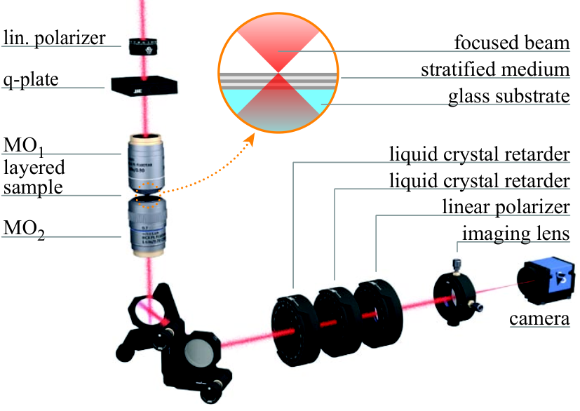
Figure 2 illustrates our experimental setup Banzer et al. 2010. We transmit a Gaussian beam (wavelength = 532 nm, linewidth 4 nm) through a linear polarizer (LP) and a q-plate of charge Marrucci et al. 2006; Larocque et al. 2016. Depending on the relative angle between the LP and the q-plate, this results in a radially, azimuthally or one of two spirally polarized doughnut-shaped beams SP1 and SP2 . For comparison, we also performed the measurements for linear - and -polarized input beams.
The investigated stratified medium on top of a glass substrate was fabricated by Iridian Spectral Technologies such that at the angle of incidence of for the wavelength of 532 nm. The numerical aptertures (NA) of the two MOs were chosen to be larger than 0.5 to cover this angle.
Additionally, we repeated the measurements on a bare glass substrate with refractive index of and thickness of . Since the coherence length of our laser is only , such a measurement provides reference data for the case where the sample does not introduce a phase shift between and -polarizations Yeh et al. 1977.
We use two liquid crystal variable retarders and an LP to project the transmitted beam onto an arbitrary polarization state. Finally, we image the polarization resolved intensity distribution in the BFP2 onto a CMOS camera for full spatial Stokes vector reconstruction.
First, Figure 3 (I) shows the measured input intensity distributions , where and are the measured input intensities of the RCP and LCP polarizations. The red arrows depict the corresponding polarization patterns. Secondly, in Figure 3 (II) and (III) we plot the intensity distribution and the normalized third Stokes parameters of the light transmitted through the stratified sample. The insets show the theoretical predictions. As expected, the radial and azimuthal beams do not generate CPL, while both spiral beams SP1 and SP2 strongly couple to CPL with the sign of the transmitted depending on the spiral orientation of the incoming beam or, equivalently on the sign of Kelvin’s chriality (see Fig. 3 (III) (a)-(d)). In fact, for the angle of () we achieve almost perfect coupling to CPL with values of approaching , as expected from Eqs. (3). For linear input polarizations, the cylindrical symmetry of the beam is broken, resulting in a four-fold pattern of CPL in Figure 3 (III) (e) and (f). Nevertheless, since linearly polarized beams do not possess any Kelvin’s chirality, their average generated is zero. Finally, in Figure 3 (IV) and (V) we present the transmission measurements through the glass sample. Here, in Figure 3 (V) (a)-(d) we observe only a residual pattern of with zero average, resembling the measurements for the radial and azimuthal polarization through the stratified medium (III) or the glass sample (V) (a) and (c). This resemblance indicates that the residual originates from the imperfections of the q-plate, as confirmed by the measurements of linear polarizations transmitted through the glass substrate in Figure 3 (V) (e) and (f), which we performed without the q-plate.
IV Discussion and Conclusion

To comprehend the role of Kelvins’ chirality it is worth discussing our result from the point of view of geometry, material composition and conservation laws.
First, in chiral light-matter interactions it is not exclusively the chirality of matter that couples to optical chirality, but essentially the geometrical chirality of the whole experiment. For instance, structurally achiral planar metamolecules show chiroptical response at normal incidence, if the mirror symmetry is broken by the heterogeneous material composition of their constituents Banzer et al. 2016; Nechayev et al. 2019b. Additionally, chiroptical effects also appear if a planar structure and the k-vector of an obliquely incident CPL form a geometrically chiral arrangement Bunn 1945.
Similarly, linear dipoles can emit chiral light, when appropriately positioned close to an optical waveguide Joos et al. 2018; Neugebauer et al. 2019. In this regard, Kelvins’ chirality ensures -symmetry breaking at the level of beam geometry.
Second, we may ask which physical conservation laws permit generation of CPL in a cylindrically symmetric system? Helicity – the projection of spin on the propagation direction – characterizes the “handedness” of a beam Fernandez-Corbaton et al. 2012; Cameron et al. 2012; Cameron Robert P. et al. 2017; Barnett et al. 2012; Fernandez-Corbaton et al. 2013; Bliokh et al. 2013; Nieto-Vesperinas 2015; Nieto-Vesperinas 2017a; Nieto-Vesperinas 2017b; Fernandez-Corbaton and Rockstuhl 2017; Crimin et al. 2019; Poulikakos et al. 2019; Mackinnon 2019. Helicity is only preserved in electromagnetically dual (impedance matched) conditions, equivalent to at all angles for planar systems Fernandez-Corbaton et al. 2012; Fernandez-Corbaton et al. 2013. Neither the stratified medium nor the glass substrate preserve helicity. Our focused beam acquires circular polarization upon transmission through the stratified medium for the same physical reason that obliquely incident plane-wave CPL at an air-glass interface acquires elliptical polarization in ellipsometry measurements, i.e, the difference of the two Fresnel coefficients.
Third, we construct the spiral beams with Kelvin’s chirality by a superposition of a radially and an azimuthally polarized beams. Neither of these beams alone possesses Kelvin’s chirality. However, the radial and azimuthal beams are -even and -odd, respectively, relative to a reflection plane that contains the -axis, which breaks the -symmetry of their superposition. Surprisingly, a -even radial beam does not violate the parity odd transformation of E itself, which holds at each point of space such that (see Fig. 1(c) in Nechayev and Banzer 2019). Moreover, we consider the geometry of spiral beams along with their direction of propagation, which renders them asymmetric under time reversal () and symmetric under combined inversion. Previously, L.D. Barron defined these transformation properties as ”false chirality” in molecular systems Barron 1986a; Barron 1986b; Barron 2012 and they are still a subject of active research Bliokh et al. 2014. At the same time, corkscrew wavefronts of linearly polarized Laguerre-Gaussian beams are asymmetric under and symmetric under reversal, respectively, rendering them “truly chiral”. We envision that further classification of Kelvin’s chirality and transformation properties of structured beams may be necessary.
Finally, Kelvin’s chirality of optical beams, similarly to chirality of matter, is a function of a geometrical shape, which is independent of its optical manifestations and does not rely on any measurable observable. For instance, an unfocused spiral beam transmitted through the stratified sample would not acquire optical chirality since at normal incidence. Quantification of Kelvin’s chirality is therefore as elusive a task as quantification of chirality of matter, for which many attempts have been made, but no universal measure has been established to date Buda and Mislow 1992; Buda et al. 1992; Rassat and Fowler 2004; Fowler 2005; Efrati and Irvine 2014; Fernandez-Corbaton et al. 2016; Gutsche et al. 2020.
In conclusion, we presented an experiment where the geometrical chirality of an optical beam, termed here as Kelvin’s chirality and manifested as parity asymmetric spatial polarization distribution, couples to optical chirality upon transmission of a focused beam through a planar medium in a cylindrically symmetric scenario. We elucidated the underlying mechanism of chiral light-matter interaction by symmetry, material composition, helicity conservation laws and a simple analytical model. Our results emphasize that spatially inhomogeneous phase and polarisation profiles of structured light beams constitute an important degree of freedom in chiral light-matter interactions beyond optical chirality.
Acknowledgments
R.A. acknowledges the support of the Alexander von Humboldt Foundation through the Feodor Lynen Fellowship. R.A. and R.W.B. acknowledge support through the Natural Sciences and Engineering Research Council of Canada,the Canada Research Chairs program, and the Canada First Research Excellence Fund.
References
- Sir William Thomson Lord Kelvin (1894) Sir William Thomson Lord Kelvin, The Molecular Tactics of a Crystal (Oxford Clarendon Press, 1894).
- Barron (1986a) L. D. Barron, Chemical Physics Letters 123, 423 (1986a).
- Barron (1986b) L. D. Barron, Chem. Soc. Rev. 15, 189 (1986b).
- Barron (2012) L. D. Barron, Chirality 24, 879 (2012).
- Buda and Mislow (1992) A. B. Buda and K. Mislow, Journal of the American Chemical Society 114, 6006 (1992).
- Buda et al. (1992) A. B. Buda, T. A. der Heyde, and K. Mislow, Angewandte Chemie International Edition in English 31, 989 (1992).
- Rassat and Fowler (2004) A. Rassat and P. W. Fowler, Chemistry – A European Journal 10, 6575 (2004).
- Fowler (2005) P. W. Fowler, Symmetry: Culture and Science 16, 321 (2005).
- Efrati and Irvine (2014) E. Efrati and W. T. Irvine, Physical Review X 4, 011003 (2014).
- Fernandez-Corbaton et al. (2016) I. Fernandez-Corbaton, M. Fruhnert, and C. Rockstuhl, Phys. Rev. X 6, 031013 (2016).
- Gutsche et al. (2020) P. Gutsche, X. Garcia-Santiago, P. I. Schneider, K. M. McPeak, M. Nieto-Vesperinas, and S. Burger, Symmetry 12, 158 (2020), 1808.01855 .
- Tang and Cohen (2010) Y. Tang and A. E. Cohen, Phys. Rev. Lett. 104, 163901 (2010).
- Bliokh and Nori (2011) K. Y. Bliokh and F. Nori, Phys. Rev. A 83, 021803(R) (2011).
- Coles and Andrews (2012) M. M. Coles and D. L. Andrews, Phys. Rev. A 85, 063810 (2012).
- Andrews and Coles (2012) D. L. Andrews and M. M. Coles, Opt. Lett. 37, 3009 (2012).
- Bliokh et al. (2014) K. Y. Bliokh, Y. S. Kivshar, and F. Nori, Phys. Rev. Lett. 113, 033601 (2014).
- Nieto-Vesperinas (2017a) M. Nieto-Vesperinas, Philosophical Transactions of the Royal Society of London A 375, 20160314 (2017a).
- Cameron Robert P. et al. (2017) Cameron Robert P., Götte Jörg B., Barnett Stephen M., and Yao Alison M., Philosophical Transactions of the Royal Society A: Mathematical, Physical and Engineering Sciences 375, 20150433 (2017).
- Crimin et al. (2019) F. Crimin, N. Mackinnon, J. Götte, and S. Barnett, Applied Sciences 9, 828 (2019).
- Poulikakos et al. (2019) L. V. Poulikakos, J. A. Dionne, and A. García-Etxarri, Symmetry 11 (2019), 10.3390/sym11091113.
- Mackinnon (2019) N. Mackinnon, Journal of Optics 21, 125402 (2019).
- Valev et al. (2013) V. K. Valev, J. J. Baumberg, C. Sibilia, and T. Verbiest, Advanced Materials 25, 2517 (2013).
- Bradshaw et al. (2015) D. S. Bradshaw, J. M. Leeder, M. M. Coles, and D. L. Andrews, Chemical Physics Letters 626, 106 (2015).
- Lodahl et al. (2017) P. Lodahl, S. Mahmoodian, S. Stobbe, A. Rauschenbeutel, P. Schneeweiss, J. Volz, H. Pichler, and P. Zoller, Nature 541, 473 (2017).
- Woody (1995) R. W. Woody, in Biochemical Spectroscopy, Methods in Enzymology, Vol. 246 (Academic Press, 1995) pp. 34 – 71.
- Barron (2004) L. D. Barron, Molecular Light Scattering and Optical Activity, 2nd ed. (Cambridge University Press, 2004).
- Berry and Dennis (2001) M. V. Berry and M. R. Dennis, Proceedings of the Royal Society of London. Series A: Mathematical, Physical and Engineering Sciences 457, 2251 (2001).
- Leach et al. (2004) J. Leach, M. R. Dennis, J. Courtial, and M. J. Padgett, Nature 432, 165 (2004).
- Larocque et al. (2018) H. Larocque, D. Sugic, D. Mortimer, A. J. Taylor, R. Fickler, R. W. Boyd, M. R. Dennis, and E. Karimi, Nature Physics 14, 1079 (2018).
- Bauer et al. (2015) T. Bauer, P. Banzer, E. Karimi, S. Orlov, A. Rubano, L. Marrucci, E. Santamato, R. W. Boyd, and G. Leuchs, Science 347, 964 (2015).
- Toyoda et al. (2012) K. Toyoda, K. Miyamoto, N. Aoki, R. Morita, and T. Omatsu, Nano Letters 12, 3645 (2012).
- Wong et al. (2012) G. K. L. Wong, M. S. Kang, H. W. Lee, F. Biancalana, C. Conti, T. Weiss, and P. S. J. Russell, Science 337, 446 (2012).
- Gorodetski et al. (2013) Y. Gorodetski, A. Drezet, C. Genet, and T. W. Ebbesen, Phys. Rev. Lett. 110, 203906 (2013).
- Forbes and Andrews (2018) K. A. Forbes and D. L. Andrews, Opt. Lett. 43, 435 (2018).
- Nechayev et al. (2019a) S. Nechayev, J. S. Eismann, G. Leuchs, and P. Banzer, Phys. Rev. B 99, 075155 (2019a).
- Woźniak et al. (2019) P. Woźniak, I. D. Leon, K. Höflich, G. Leuchs, and P. Banzer, Optica 6, 961 (2019).
- Forbes and Andrews (2019a) K. A. Forbes and D. L. Andrews, Phys. Rev. A 99, 023837 (2019a).
- Forbes and Andrews (2019b) K. A. Forbes and D. L. Andrews, Phys. Rev. Research 1, 033080 (2019b).
- Eismann et al. (2018) J. S. Eismann, M. Neugebauer, and P. Banzer, Optica 5, 954 (2018).
- Nechayev and Banzer (2019) S. Nechayev and P. Banzer, Phys. Rev. B 99, 241101 (2019).
- Fernandez-Corbaton et al. (2012) I. Fernandez-Corbaton, X. Zambrana-Puyalto, and G. Molina-Terriza, Phys. Rev. A 86, 042103 (2012).
- Cameron et al. (2012) R. P. Cameron, S. M. Barnett, and A. M. Yao, New Journal of Physics 14, 053050 (2012).
- Barnett et al. (2012) S. M. Barnett, R. P. Cameron, and A. M. Yao, Phys. Rev. A 86, 013845 (2012).
- Fernandez-Corbaton et al. (2013) I. Fernandez-Corbaton, X. Zambrana-Puyalto, N. Tischler, X. Vidal, M. L. Juan, and G. Molina-Terriza, Phys. Rev. Lett. 111, 060401 (2013).
- Bliokh et al. (2013) K. Y. Bliokh, A. Y. Bekshaev, and F. Nori, New Journal of Physics 15, 033026 (2013).
- Nieto-Vesperinas (2015) M. Nieto-Vesperinas, Phys. Rev. A 92, 023813 (2015).
- Nieto-Vesperinas (2017b) M. Nieto-Vesperinas, Journal of Optics 19, 065402 (2017b).
- Fernandez-Corbaton and Rockstuhl (2017) I. Fernandez-Corbaton and C. Rockstuhl, Phys. Rev. A 95, 053829 (2017).
- Novotny and Hecht (2012) L. Novotny and B. Hecht, Principles of Nano-Optics (Cambridge University Press, Cambridge, 2012).
- Zhan and Leger (2002) Q. Zhan and J. R. Leger, Opt. Express 10, 324 (2002).
- Nechayev et al. (2020) S. Nechayev, J. S. Eismann, M. Neugebauer, and P. Banzer, ACS Photonics 7, 581 (2020), 1909.13365 .
- Yeh et al. (1977) P. Yeh, A. Yariv, and C.-S. Hong, J. Opt. Soc. Am. 67, 423 (1977).
- Banzer et al. (2010) P. Banzer, U. Peschel, S. Quabis, and G. Leuchs, Opt. Express 18, 10905 (2010).
- Marrucci et al. (2006) L. Marrucci, C. Manzo, and D. Paparo, Phys. Rev. Lett. 96, 163905 (2006).
- Larocque et al. (2016) H. Larocque, J. Gagnon-Bischoff, F. Bouchard, R. Fickler, J. Upham, R. W. Boyd, and E. Karimi, Journal of Optics 18, 124002 (2016).
- Banzer et al. (2016) P. Banzer, P. Woniak, U. Mick, I. De Leon, and R. W. Boyd, Nature Communications 7, 1 (2016), 1601.01900 .
- Nechayev et al. (2019b) S. Nechayev, R. Barczyk, U. Mick, and P. Banzer, ACS Photonics 6, 1876 (2019b), 1905.02619 .
- Bunn (1945) C. W. Bunn, Chemical Crystallography (Oxford University Press, 1945).
- Joos et al. (2018) M. Joos, C. Ding, V. Loo, G. Blanquer, E. Giacobino, A. Bramati, V. Krachmalnicoff, and Q. Glorieux, Phys. Rev. Applied 9, 064035 (2018).
- Neugebauer et al. (2019) M. Neugebauer, P. Banzer, and S. Nechayev, Science Advances 5 (2019), 10.1126/sciadv.aav7588.