Performance of Large-Format Deformable Mirrors Constructed with TNO Variable Reluctance Actuators
Abstract
Advancements in making high-efficiency actuators are an enabling technology for building the next generation of large-format deformable mirrors. The Netherlands Organization for Applied Scientific Research (TNO) has developed a new style of variable-reluctance actuator that requires approximately eighty times less power to operate as compared to the traditional style of voice-coil actuators. We present the performance results from laboratory testing of TNO’s 57-actuator large-format deformable mirror from measuring the influence functions, linearity, hysteresis, natural shape flattening, actuator cross-coupling, creep, repeatability, and actuator lifetime. We measure a linearity of 99.4 0.33% and hysteresis of 2.10 0.23% over a stroke of 10 microns, indicating that this technology has strong potential for use in on-sky adaptive secondary mirrors (ASMs). We summarize plans for future lab prototypes and ASMs that will further demonstrate this technology.
keywords
Adaptive Optics, Adaptive Secondary Mirrors, Large Format Deformable MirrorsR.B.R.: E-mail: rbowru@ucsc.edu
1 INTRODUCTION
Adaptive secondary mirrors have been used successfully at telescopes like the Large Binocular Telescope [1], Magellan [2], the VLT Observatory [3], and the MMT Observatory [4]. However, these adaptive secondary mirror systems are complex because they incorporate hundreds of power intensive voice-coil actuators that require a dedicated cooling system and capacitive sensors [5]. The mirror facesheet fabrication has also traditionally required the grinding of a large piece of glass into a thin glass sheet that is flexible enough to be shaped by the actuators.
The Netherlands Organization for Applied Scientific Research (TNO) has made significant breakthroughs in large-format deformable mirror technology that could enable adaptive secondary mirrors to become simpler and less costly. The key advancement is a new style of hybrid variable reluctance actuator that is 80 times more efficient than traditional voice-coil actuators (TNO actuator efficiency [6] = ; MMT and LBT actuator efficiency [7] = ). The low required power offers a pathway to eliminate the actuator cooling system, miniaturize the system, and pack the actuators at higher density. TNO is also developing solutions that could simplify the facesheet fabrication by starting with thin glass sheets and utilizing glass-slumping techniques to form the shape.
While these mirrors show great potential to make advanced adaptive optics systems accessible to a wide variety of observatories, they have yet to be proven to the astronomical community. This paper presents laboratory testing performed of TNO’s third deformable-mirror prototype (DM3) to explore the properties of TNO’s large-format deformable mirror technology. We report the results of this testing and outline the future steps towards deployment of this technology on-sky.
2 TECHNOLOGY OVERVIEW
2.1 Design of the TNO DM3
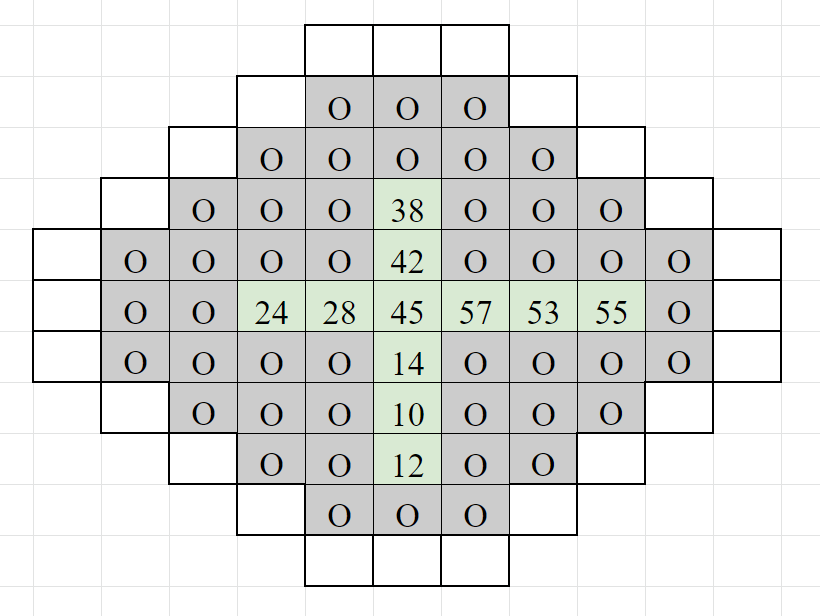
The DM3 is the third prototype large-format deformable mirror from TNO (Figure 1). It was built for lab demonstration in 2016. The surface is round (⌀150mm) and flat to within 15.5 um peak-to-valley when the applied actuator current is zero. DM3 was built using 57 actuators of 18mm pitch (Figure 2).
The mirror is controlled through a 64 analog output from a Real Time Linux environment. The output voltages are controlled using an RDA interface to Matlab running on an office PC. The user can control the shape of the mirror’s surface by setting the current applied to each actuator. The update rate of this setup is 300Hz.


2.2 TESTBENCH SETUP
The University of California Santa Cruz Lab for Adaptive Optics (UCSC-LAO) began testing the TNO DM3 in January of 2020. The testbed at UCSC-LAO (Figure 3) utilizes a Zygo Interferometer run with Metropro Software to measure the shape of the mirror’s surface to a precision of 0.6 nm. Additional Matlab code is being developed by UCSC-LAO to streamline the process of characterizing the actuator linearity, hysteresis, creep, cross-coupling, repeatability, Zernike pattern replication, and lifetime using this testbench. A cold chamber and orientation setup will be integrated for future environmental and gravity testing.
 |
3 DM3 TESTING RESULTS
3.1 Influence Functions
The influence function of each actuator was measured using an individual actuator poke test. A current was applied in an automated measurement sequence to displace each actuator one-by-one. The displacement of these pokes corresponded to approximately 730nm peak-to-valley. Twenty-one actuators responded to the positive current with a positive displacement, and thirty-six actuators responded with a negative displacement.
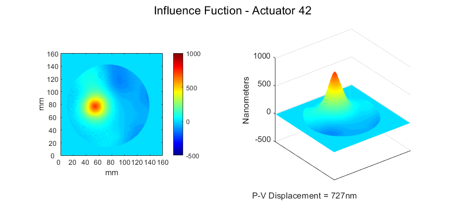
An example of the influence function measured for Actuator 42 is shown in Figure 4. The influence function was measured with the natural shape of the mirror subtracted such that only the displacement is seen. The cross-section of the influence function is plotted in Figure 5 with a Gaussian, Moffat, and Cauchy function fit. While each of the three functions can approximate part of the profile, a custom profile would need to be created to correctly fit the actuator cross sections at both the center and tails.
 |
 |
3.2 Natural-Shape Surface Flattening
The natural shape of the TNO DM3 mirror has a peak-to-valley that is 15.5 um with a 2780nm RMS variation (within 140mm). To bring the surface as flat as possible, a set of currents that could bring the mirror surface to the lowest RMS possible was determined using an iterative process. At each step, an image was taken using the Zygo. The next desired position for the actuators to reproduce in the iteration () was set to the negative of the last image taken (). The next set of currents () to produce the desired shape () were calculated using the influence functions matrix () through the Moore-Penrose inverse:
| (1) |
The new currents from the iteration were then summed with the previous currents applied to find the new values to be applied ().
On April 30th 2020, fifteen iterations of flattening were performed to calculate the optimal flattening currents. The majority of the variation was removed after five iterations. The flattest shape was found on iteration 14 which had an RMS = 27.7nm (within 140mm) with a peak-to-valley of 469nm, demonstrating that it is possible to flatten the surface by two orders of magnitude. Figure 6 shows the natural shape of the mirror alongside the shape after this flattening.
The total current needed to hold this shape across the 57 actuators was 1967mA, averaging 34.5 6.6mA per actuator. The required power was 189mW (3.3 mW/actuator). Riccardi et al. (2003, Table 1) states the power required for a correction to a similar wavefront error with the LBT ASM requires 190 mW/actuator. [7], leading to a nearly sixty factor gain in this comparison. This estimate does not include the additional 3.8 W/actuator of power needed at the LBT collocated electronics crate, which is located slightly further from the mirror but still on the secondary structure.
 |
3.3 Zernike Mode Testing
To determine how close DM3 was able reproduce ideal Zernike shapes, the first 57 Zernike Modes were applied to DM3. The currents needed to reproduce the Zernike modes were calculated using Equation 1, where was the shape of each Zernike pattern. No iterations were used in trying to reproduce the Zernike pattern. An example of the side-by-side comparison between DM3 and an ideal Zernike pattern can be viewed in Figure 7 for mode 12. A movie of the full test can be watched at the following youtube link: https://youtu.be/dpTzO46zg2Y.
To determine if a trend existed between the Zernike order number and how well the mirror could replicate the pattern, the reduced chi square was calculated for each Zernike frame (Figure 8). Modes with a large reduced chi square value could not be replicated to as high precision. Overall, the spherical modes were reproduced the least well (4, 12, 24, 40) of any categorization of mode type. There was not a significant trend between the value of the reduced chi square and low or high order mode number.
 |
 |
3.4 Actuator Cross-Coupling
The actuator cross-coupling was measured to quantify how the movement of one actuator will affect its neighbor. The cross-coupling was measured using the cross section of the influence functions from the center row and center column of actuators (Figure 9). The center actuator (45) was used in both samples.
The cross sections were corrected for their positive/negative displacement polarity and then normalized. Two measurements were taken per actuator along the line that intersected the neighboring actuator’s peak. Using these twenty measurements, we measure an actuator cross-coupling of 37.07 0.93%.
 |
3.5 Linearity
Linearity testing was performed using five actuators (12, 14, 42, 55, and 57). These actuators were run through a fifteen-step current pattern using positive and negative currents, spanning from 0 to +140mA or 0 to -140mA (Figure 10). Although the negative and positive current runs were performed separately, linearity fitting considered the tests jointly for each actuator. The displacement was measured using the mean of the seven points nearest to the actuator center.
The displacement data were fit for each actuator (Figure 11). The slopes of the fit for each actuator were averaged to reveal a displacement of 39.66 0.54 nm/mA. The linearity data for the five actuators is presented in Figure 11 with the percent residuals. The percent residuals were calculated using,
| (2) |
The mean of the percent residuals across the five actuators was used to quantify the actuator linearity. We measure the actuators to be linear to 99.4% 0.33% (nonlinear to 0.6% 0.33%). The nonlinearity is most evident at small currents (within 20mA) where the actuators tend to undershoot their predicted position.


 |
3.6 Hysteresis
Actuator displacement varies depending on the previous position of the actuator. To quantify this, we measured the hysteresis using the definition:
| (3) |
where and are the displacements measured at an applied current of zero and and are the displacements measured at the maximum and minimum current applied.
Hysteresis testing was performed using three actuators (14, 42, and 57) stepped through five independent hysteresis loops. Each loop was done in forty steps between currents of 5mA, 10mA, 20mA, 60mA, 120mA (Figure 10). Three of these tests occurred in the least linear portions of the actuator displacement curves (5mA, 10mA, 20mA) and provide worse-case scenario measurements of the hysteresis. No measurement exceeded a hysteresis value of 3.5%. The average percent hysteresis measured across all fifteen trials was 2.10 0.23% (Figure 12).


3.7 Repeatability
A repeatability test was run to verify the ability for the DM3 to return to the same shape when applying the same set of currents from day to day. The repeatability testing was performed by applying the flattening current set calculated on April 30th 2020. Five measurements were taken across five days starting from zero currents applied. Images were visually inspected and the RMS was used to quantify the shape. The images passed visual inspection and the RMS did not change to within the precision of the Zygo Interferometer (0.6nm).
The same shape was applied after the mirror had been running for unmeasured amounts of times. The RMS differences in these images were observed to fluctuate by up to nm.
3.8 Creep
Creep testing was performed by applying a current pattern and holding it for twelve hours. Similar to the repeatability testing, the creep testing was run by applying the flattening current pattern found on April 30th 2020. Measurements were taken with the applied pattern subtracted such that the Zygo images were more sensitive to any deviations. The tests were repeated three times.
The only measurable change came from an added tilt on the order of 1000nm that was believed to be from a shift in the beam expander mounting. Although the data cannot conclusively rule out creep as an issue to <1000nm RMS, there is no evidence for significant creep.
3.9 Lifetime Testing
A demonstration to test the working lifetime of the actuators is in progress. The 57 actuators were set to a 34Hz cycle going from -50% to +50% of the maximum stroke. This scenario is a strong worst case for an actual ASM in operation, where the changes in deflection for each cycle will be much lower. Periodically, DM3 is imaged with the Zygo interferometer. At the time of writing, each of the 57 actuators has seen over 110 million cycles with no detectable change in performance.
4 CONCLUSIONS
4.1 Summary of Results
The key results from each test of the TNO DM3 are summarized in Table 1. The values determined from the laboratory testing at UCSC-LAO of the TNO DM3 are consistent with the values quoted by TNO. The TNO variable reluctance actuators show a linearity and hysteresis value similar to the voice-coil actuators currently used in on-sky adaptive secondary mirrors while exhibiting over 5.5 times lower power consumption.
| Section | Test | Takeaway | |||||
|---|---|---|---|---|---|---|---|
| 3.1 | Influence functions |
| |||||
| 3.2 |
|
| |||||
| 3.3 | Zernike Mode |
| |||||
| 3.4 | Actuator Cross-Coupling | Cross Coupling = 37.07 0.93% | |||||
| 3.5 | Linearity |
| |||||
| 3.6 | Hysteresis | Hyst = 2.10 0.23% | |||||
| 3.7 | Repeatability |
| |||||
| 3.8 | Creep |
| |||||
| 3.9 | Lifetime |
|
4.2 Technology Development Plan
TNO is in the process of constructing its first on-sky adaptive secondary mirror for use in the UH-88 telescope located on Maunakea. This adaptive secondary mirror has an aspherical convex shape that is ⌀63cm. It is fabricated using 210 actuators from the 2020 generation that can accommodate larger actuator spacing and be arranged in a circular grid. This system is expected to be ready for lab testing in the summer of 2021 and be deployed in the telescope in early 2022. More information about the UH-88 ASM can be found in this conference’s proceedings at SPIE No. 1144852 Chun et. al. 2020.
TNO is developing two future lab-model prototypes for use at UCSC-LAO. By December 2020, TNO will deliver the First Laboratory Adaptive Secondary Holophote (FLASH) (Figure 13). FLASH has a flat surface of ⌀160mm. It is constructed using 19 actuators from the 2020 version developed for the UH-88 ASM. The testing presented in this paper will be repeated to verify the properties of the new actuators. Additional testing will also be performed to explore the effects of temperature, gravity, and any unexplained behaviors found in the UH-88 ASM.
Following the FLASH, the Second Laboratory Adaptive Secondary Holophote (SLASH) will be constructed using an aspherical convex facesheet. The SLASH will be ⌀370mm and contain 61 actuators from the next generation. While the SLASH design is still being finalized, we are investigating the possibilities of integrating this prototype into the UC Lick Observatory’s Automated Planet Finder telescope as an adaptive secondary mirror. If this design is selected, SLASH may become the first on-sky ASM to be paired with a precision radial velocity instrument.
Both FLASH and SLASH will be constructed using thin facesheets formed using glass slumping techniques. This glass slumping is done in-house at the UCSC-LAO using flat borofloat sheets. The glass is heated in a glass kiln and let sag into a fused silica mold over the course of several days. It is then optically coated with aluminium to create a mirrored surface. UCSC-LAO has produced the 160mm flat facesheet for the FLASH using this technique in order to promote the technology readiness level of this fabrication approach. This technique will be developed to expand to meter sizes, greatly reducing the costs associated with producing flexible glass facesheets for use in ASMs for large telescopes.
Design studies are in progress to understand the feasibility and constraints of building an adaptive secondary mirror for the UCO Lick Automated Planet Finder Telescope and the W.M. Keck Observatory with TNO technology. More information about these designs can be found in this conference’s proceedings at SPIE No. 11448-233 Hinz et. al. 2020.


|
|
|
Facesheet |
|
Status | ||||||||||
| DM3 | 57 | 150 |
|
|
Analog |
| |||||||||
| FLASH | 19 | 160 |
|
|
Analog |
| |||||||||
|
61 | 400 |
|
|
Digital | TBD |
References
- [1] Esposito, S., Riccardi, A., Fini, L., Puglisi, A. T., Pinna, E., Xompero, M., Briguglio, R., Quirós-Pacheco, F., Stefanini, P., Guerra, J. C., Busoni, L., Tozzi, A., Pieralli, F., Agapito, G., Brusa-Zappellini, G., Demers, R., Brynnel, J., Arcidiacono, C., and Salinari, P., “First light AO (FLAO) system for LBT: final integration, acceptance test in Europe, and preliminary on-sky commissioning results,” in [Adaptive Optics Systems II ], Ellerbroek, B. L., Hart, M., Hubin, N., and Wizinowich, P. L., eds., Society of Photo-Optical Instrumentation Engineers (SPIE) Conference Series 7736, 773609 (July 2010).
- [2] Close, L. M., Males, J. R., Morzinski, K. M., Esposito, S., Riccardi, A., Briguglio, R., Follette, K. B., Wu, Y.-L., Pinna, E., Puglisi, A., Xompero, M., Quiros, F., and Hinz, P. M., “Status of MagAO and review of astronomical science with visible light adaptive optics,” in [Adaptive Optics Systems VI ], Close, L. M., Schreiber, L., and Schmidt, D., eds., Society of Photo-Optical Instrumentation Engineers (SPIE) Conference Series 10703, 107030L (July 2018).
- [3] Biasi, R., Andrighettoni, M., Angerer, G., Mair, C., Pescoller, D., Lazzarini, P., Anaclerio, E., Mantegazza, M., Gallieni, D., Vernet, E., Arsenault, R., Madec, P. Y., Duhoux, P., Riccardi, A., Xompero, M., Briguglio, R., Manetti, M., and Morandini, M., “VLT deformable secondary mirror: integration and electromechanical tests results,” in [Adaptive Optics Systems III ], Ellerbroek, B. L., Marchetti, E., and Véran, J.-P., eds., Society of Photo-Optical Instrumentation Engineers (SPIE) Conference Series 8447, 84472G (July 2012).
- [4] Wildi, F. P., Brusa, G., Lloyd-Hart, M., Close, L. M., and Riccardi, A., “First light of the 6.5-m MMT adaptive optics system,” in [Astronomical Adaptive Optics Systems and Applications ], Tyson, R. K. and Lloyd-Hart, M., eds., Society of Photo-Optical Instrumentation Engineers (SPIE) Conference Series 5169, 17–25 (Dec. 2003).
- [5] Hinz, P. M., Defrère, D., Skemer, A., Bailey, V., Stone, J., Spalding, E., Vaz, A., Pinna, E., Puglisi, A., Esposito, S., Montoya, M., Downey, E., Leisenring, J., Durney, O., Hoffmann, W., Hill, J., Millan-Gabet, R., Mennesson, B., Danchi, W., Morzinski, K., Grenz, P., Skrutskie, M., and Ertel, S., “Overview of LBTI: a multipurpose facility for high spatial resolution observations,” in [Optical and Infrared Interferometry and Imaging V ], Malbet, F., Creech-Eakman, M. J., and Tuthill, P. G., eds., Society of Photo-Optical Instrumentation Engineers (SPIE) Conference Series 9907, 990704 (Aug. 2016).
- [6] Kuiper, S., Doelman, N., Human, J., Saathof, R., Klop, W., and Maniscalco, M., “Advances of TNO’s electromagnetic deformable mirror development,” in [Advances in Optical and Mechanical Technologies for Telescopes and Instrumentation III ], Navarro, R. and Geyl, R., eds., Society of Photo-Optical Instrumentation Engineers (SPIE) Conference Series 10706, 1070619 (July 2018).
- [7] Riccardi, A., Brusa, G., Salinari, P., Gallieni, D., Biasi, R., Andrighettoni, M., and Martin, H. M., “Adaptive secondary mirrors for the Large Binocular Telescope,” in [Adaptive Optical System Technologies II ], Wizinowich, P. L. and Bonaccini, D., eds., Society of Photo-Optical Instrumentation Engineers (SPIE) Conference Series 4839, 721–732 (Feb. 2003).