Planetesimal formation around the snow line. II. Dust or pebbles?
Abstract
Context. Forming planetesimals is a major challenge in our current understanding of planet formation. Around the snow line, icy pebbles and silicate dust may locally pile up and form icy and rocky planetesimals via a streaming instability and/or gravitational instability. The scale heights of both pebbles and silicate dust released from sublimating pebbles are critical parameters that regulate the midplane concentrations of solids.
Aims. Here, using a realistic description of the scale height of silicate dust and that of pebbles, we wish to understand disk conditions for which a local runaway pile-up of solids (silicate dust or icy pebbles) occurs inside or outside the snow line.
Methods. We performed 1D diffusion-advection simulations that include the back-reaction (the inertia) to radial drift and diffusion of icy pebbles and silicate dust, ice sublimation, the release of silicate dust, and their recycling through the recondensation and sticking onto pebbles outside the snow line. We used a realistic description of the scale height of silicate dust obtained from a companion paper and that of pebbles including the effects of a Kelvin-Helmholtz (KH) instability. We study the dependence of solid pile-up on distinct effective viscous parameters for turbulent diffusions in the radial and vertical directions ( and ) and for the gas accretion to the star () as well as that on the pebble-to-gas mass flux ().
Results. Using both analytical and numerical approaches, we derive the sublimation width of drifting icy pebbles which is a critical parameter to characterize the pile-up of silicate dust and pebbles around the snow line. We identify a parameter space (in the space) where pebbles no longer drift inward to reach the snow line due to the back-reaction that slows down the radial velocity of pebbles (we call this the ”no-drift” region). We show that the pile-up of solids around the snow line occurs in a broader range of parameters for than for . Above a critical value, the runaway pile-up of silicate dust inside the snow line is favored for , while that of pebbles outside the snow line is favored for . Our results imply that a distinct evolutionary path in the space could produce a diversity of outcomes in terms of planetesimal formation around the snow line.
Key Words.
Planets and satellites: formation, Planet-disk interactions, Accretion, accretion disks1 Introduction
Forming planetesimals in protoplanetary disks is a major challenge in our current understanding of planet formation. Streaming instability (SI) (Youdin & Goodman 2005, e.g.,) and gravitational instability (GI) (Goldreich & Ward 1973, e.g.,) could be prominent candidate mechanisms to directly form planetesimals from small particles, although the detailed conditions and applicability are still a matter of debate.
The water snow line may be a favorable location where solids selectively pile up (Fig. 1). During the passage of icy pebbles drifting through the water snow line, icy pebbles sublimate and silicate dust is ejected11 1 A critical collision velocity for rebound and fragmentation is conventionally expected to be times lower for silicate than for ice (Blum & Wurm 2000; Wada et al. 2011, e.g.,), although recent studies showed updated sticking properties of silicate (Kimura et al. 2015; Gundlach et al. 2018; Musiolik & Wurm 2019; Steinpilz et al. 2019, e.g.,). (Saito & Sirono 2011; Morbidelli et al. 2015). The formation of icy planetesimals by the streaming instability outside the snow line could be triggered via the local enhancement of pebble spatial density through the recondensation of diffused water vapor and sticking of silicate dust onto pebbles beyond the snow line (Schoonenberg & Ormel 2017; Dra̧żkowska & Alibert 2017; Hyodo et al. 2019). Inside the snow line, rocky planetesimals might be preferentially formed by the gravitational instability of piled up silicate dust because the drift velocity suddenly drops there as the size significantly decreases from sublimating pebbles (Ida & Guillot 2016; Hyodo et al. 2019).
Recent 1D numerical simulations aimed to study the pile-up of solids around the water snow line (Saito & Sirono 2011; Morbidelli et al. 2015; Estrada et al. 2016; Ida & Guillot 2016; Schoonenberg & Ormel 2017; Dra̧żkowska & Alibert 2017; Charnoz et al. 2019; Hyodo et al. 2019; Gárate et al. 2020). Although these different studies considered similar settings of pebbles and silicate dust, they neglected some of the following essential physical processes to regulate the midplane solid-to-gas ratio: These are, for example, (1) gas-dust friction for solids (pebbles and/or silicate dust), that is, the back-reaction to their drift velocity and diffusive motion in the radial and vertical directions, and (2) a realistic prescription of the scale height of silicate dust as well as that of pebbles.
Back-reactions that slow down drift velocities of pebbles and silicate dust as their pile-up proceeds (hereafter, Drift-BKR) are essential for pile-up as (a subscript of ”p (or d)” describes physical parameters of either pebbles or those of silicate dust), where and are the surface density and the radial velocity of pebbles or silicate dust, respectively (Ida & Guillot 2016). Back-reaction to the diffusive motion (hereafter, Diff-BKR) can trigger runaway pile-up of solids as their diffusivities are progressively weakened as pile-up proceeds (Hyodo et al. 2019, see Eqs. (21) and (22) below).
The scale height of silicate dust is another critical consideration on the solid pile-up. The midplane spatial density of silicate dust is and thus the midplane solid-to-gas ratio is directly affected by . The efficiency of the recycling (sticking) of diffused silicate dust onto pebbles outside the snow line is as the number density of colliding silicate dust is . All of the previous studies of 1D calculations used a too simple prescription for and their results overestimated or underestimated the pile-up of solids, depending on their assumed and the disk conditions (see more details in Appendix A).
In our companion paper (Ida et al. 2021; hereafter Paper I), we performed 2D (radial-vertical) Monte Carlo simulations (a Lagrange method) of silicate dust that was released around the snow line from drifting icy pebbles under ice sublimation. Based on these Monte Carlo simulations and using semi-analytical arguments, Paper I derived a formula for the evolving scale height of the silicate dust for a given disk parameters as a function of the distance to the snow line (Eq. (36) below). The derived scale height of silicate dust is a function of the radial width where the dust is released from sublimating pebbles (i.e., sublimation width of pebbles; see Eq. (36)). However, Paper I did not include the physical processes of the sublimation. Here, our 1D code is suitable for including the pressure-dependent sublimation around the snow line and we study the sublimation width of the drifting pebbles (Section 3).
Paper I also studied conditions for the pile-up of silicate dust just inside the snow line and identified disk parameters where runaway pile-up of silicate dust occurs (i.e., rocky planetesimal formation). However, Paper I did not include recycling of water vapor and of silicate dust outside the snow line due to their diffusive motion and hence they did not consider pile-up process of pebbles outside the snow line.
The scale height of pebbles is a function of the Stokes number (larger pebbles tend to reside in a vertically thinner disk midplane layer). However, for a sufficiently thin pebble-dominated midplane layer may interact with the upper/lower gas-dominated layer, inducing a Kelvin-Helmholtz (KH) instability (Sekiya 1998; Chiang 2008), which was not considered before. Here, we also consider the effects of a KH instability for a more realistic picture of the scale height of pebbles and their midplane concentration (Section 4.1).
In reality, pile-ups of silicate dust and/or pebbles around the snow line are the consequence of combinations of ice sublimation, dust release, and their recycling onto pebbles together with their complex radial and vertical motions (Fig. 1). In this work, we perform new 1D simulations that include both Drift-BKR and Diff-BKR (Hyodo et al. 2019, the same as) and that adopt, for the first time, a realistic scale height of silicate dust (derived in Paper I) and that of pebbles (derived in Section 4.1). We discuss favorable conditions for runaway pile-ups of pebbles and/or silicate dust by investigating a much broader disk parameter space than previous studies.
In Section 2, we explain our numerical methods and models. In Section 3, using 1D numerical simulations and analytical arguments, we derive sublimation width of drifting icy pebbles, which is a critical parameter to regulate a local solid pile-up around the snow line. In Section 4, we derive the scale height of pebbles considering the effects of a KH instability, and we also derive a critical above which pebble drift is stopped due to the back-reaction onto the gas that slows down the radial velocity of pebbles. In Section 5, we show our overall results of 1D simulations that combined with a realistic scale heights of silicate dust and pebbles. In Section 6, we summarize our paper.

2 Numerical methods and models
Here, we describe numerical methods and models. In this paper, we use three distinct non-dimensional parameters to describe the gas-solid evolutions in protoplanetary disk: which describes the global efficiency of angular momentum transport of gas (i.e., corresponds to the gas accretion rate) via turbulent viscosity , which describes the radial turbulence strength (i.e., corresponds to the radial velocity dispersion), and which describes the vertical turbulence strength (i.e., corresponds to the vertical velocity dispersion) and which is used to describe the scale height of pebbles22 2 In Hyodo et al. 2019, is used to describe and ..
The classical -disk model (Shakura & Sunyaev 1973) has adopted fully turbulent disks, i.e., , whereas recent theoretical developments suggest that the vertically averaged efficiency of the disk angular momentum transport, i.e., , could be different from local radial and vertical turbulence strengths and (Armitage et al. 2013; Liu et al. 2019, e.g.,). The gas accretion can be dominated by a process other than radial turbulent diffusion such as angular momentum transport by large-scale magnetic fields (Bai et al. 2016, e.g.,). Magnetohydrodynamic (MHD) simulations have shown that a region of ionization that is too low for the magneto-rotational instability (MRI) to operate (”dead zone”; Gammie 1996) might ubiquitously exist in the inner part of disk midplane and only surface layers are magnetically active (Gressel et al. 2015; Simon et al. 2015; Bai & Stone 2013; Bai et al. 2016; Mori et al. 2017, within a dead zone; e.g.,). These results indicate (Zhu et al. 2015; Hasegawa et al. 2017; Yang et al. 2018, see also) and we study a wide parameter range where .
2.1 Structure of the gas disk
The surface density of the gas at a radial distance is expressed as a function of the gas accretion rate and the gas radial velocity (i.e., the classical -accretion disk model; Shakura & Sunyaev 1973; Lynden-Bell & Pringle 1974) as
| (1) |
The isothermal sound speed of the gas is written as
| (2) |
where is the Boltzmann constant, is the mean molecular weight of the gas (), is the proton mass, and is the temperature of the disk gas. In this paper, the temperature profile of the disk is fixed as
| (3) |
where we use K and . Then, the scale height of the gas is given as
| (4) |
where is the Keplerian orbital frequency. Disk gas pressure at the midplane is given as
| (5) |
The gas rotates at sub-Keplerian speed. The degree of deviation of the gas rotation frequency from that of Keplerian is given by
| (6) |
where is the orbital frequency of the gas and we define
| (7) |
which depends on the gas structure. In this paper, for and .
2.2 Radial drifts of gas, pebbles, and silicate dust
The gas radial velocity including the effects of gas-solid friction is given as (Ida & Guillot 2016; Schoonenberg & Ormel 2017)
| (8) |
where is the midplane solid-to-gas ratio of pebbles or silicate dust, characterizes the strength of the back-reaction due to pile-up of either pebbles or silicate dust, is the Stokes number of pebbles or silicate dust, and is an unperturbed disk gas accretion velocity. is defined as
| (9) |
where and are the midplane spatial density of the gas and that of pebbles (or silicate dust), respectively. and are the scale heights of pebbles and silicate dust, respectively. is defined as
| (10) |
Using or , is rewritten as
| (11) | ||||
| (12) |
where . is the vertically averaged metallicities of pebbles or silicate dust. Using the dimensionless effective viscous parameter and the effective viscosity , is given as
| (13) |
where (Desch et al. 2017). For a steady-state disk, the gas accretion velocity is and is rewritten as
| (14) | ||||
| (15) |
where is the Keplerian velocity.
In this work, we adopt a vertical two-layer model to describe the radial velocity of the gas: a pebble/dust-rich midplane layer with scale height and a pebble/dust-poor upper layer. The vertically averaged radial velocity of the gas is given as
| (16) |
We note that the above simple two-layer model well reproduces the results of Kanagawa et al. 2017 where the approximation of the Gaussian distribution is used.
The radial velocities of pebbles and silicate dust including the effects of gas-solid friction drift back-reaction (Drift-BKR) are given as (Ida & Guillot 2016; Schoonenberg & Ormel 2017; Hyodo et al. 2019)
| (17) | ||||
| (18) |
where and are the Stokes number of pebbles and silicate dust, respectively.
2.3 Diffusion of gas and solids
The radial and vertical diffusivities of gas and vapor ( and ) are given as
| (19) | ||||
| (20) |
where and are the turbulent viscosities that regulate radial and vertical diffusions in association with dimensionless turbulence parameters and , respectively.
The nature of solid diffusion in the gas is partial coupling with the gas eddies (Youdin & Lithwick 2007). Hyodo et al. 2019 considered that the diffusivity of pebbles (and that of silicate dust) is reduced owing to the gas-solid friction as pile-up of solids proceeds diffusion back-reaction (Diff-BKR) and radial and vertical diffusivities of pebbles and silicate dust are given as
| (21) |
| (22) |
where is the coefficient. could be applied because the diffusivity is under a constant assumption. Using the effective gas density, , the effective sound velocity of a mixture of gas and small particles is given as
| (23) |
where is the sound velocity when (Eq. (2)). However, from an energy dissipation argument, the lower limit is . We note that the result of solid pile-up around the snow line does not significantly depend on the choice of as long as the back reaction to diffusion is included (i.e., ). In this work, we use as a representative case.
2.4 Equations of radial transport of gas, vapor, and solids
In this paper, we solve the radial motions of gas, pebbles, silicate dust, and water vapor. Pebbles are modeled as a homogenous mixture of water ice and micron-sized silicate dust (Ida & Guillot 2016; Schoonenberg & Ormel 2017; Hyodo et al. 2019, see also). Due to the sublimation of icy pebbles near the snow line, water vapor and silicate dust are produced.
The governing equations of the surface density of the gas , that of pebbles , that of silicate dust , that of water vapor , and the number density of pebbles are given as (Desch et al. 2017; Hyodo et al. 2019);
| (24) | ||||
| (25) | ||||
| (26) | ||||
| (27) | ||||
| (28) |
The right-hand sides of Eqs. (25)-(27) are due to sublimation of icy pebbles, the recondensation of water vapor, and sticking of silicate dust onto pebbles (see Hyodo et al. 2019). The evolution of needs to be solved because the size of pebbles changes during sublimation and condensation, and the mass of pebbles is given as under the single-size approximation.
The decrease rate of the pebble mass is given by (Lichtenegger & Komle 1991; Ros et al. 2019)
| (29) |
where is the particle physical radius, and are vapor and saturation spatial densities, and is the averaged normal component of the velocity passing through the particle surface. The averaged normal velocity of only outgoing particles with Maxwell distribution is
| (30) |
where is the mean molecular weight. Another definition of the thermal velocity is the averaged value of the magnitude of three-dimensional velocity, which is given by
| (31) |
Because this definition of does not include the effect of oblique ejection/collisions, the cross section must be considered rather than the surface density, that is,
| (32) |
Both Eqs. (29) and (55) give the same . We note that Schoonenberg & Ormel 2017 and Hyodo et al. 2019 used for Eq. (29), which caused overestimation of the sublimation and recombination rates by a factor of 4.
2.5 Scale heights of pebbles and silicate dust
The scale heights of pebbles and silicate dust describe the degree of concentration of solids in the disk midplane ().
In the steady-state, the scale height of pebbles is regulated by the vertical turbulent stirring (Dubrulle et al. 1995; Youdin & Lithwick 2007; Okuzumi et al. 2012) as33 3 Previous studies (Schoonenberg & Ormel 2017; Dra̧żkowska & Alibert 2017; Hyodo et al. 2019) did not consider the effects of Diff-BKR on the scale height of pebbles (i.e., is assumed for Eq. (33)).
| (33) |
However, for small (i.e., for a small ), a vertical shear Kelvin-Helmholtz (KH) instability would prevent the scale height of pebbles from being a smaller value. The scale height of pebbles regulated by a KH instability is given (see the derivation in Section 4.1) as
| (34) |
where is used here as a critical value for a KH instability to operate. Thus, the scale height of pebbles is given as
| (35) |
Using a Monte Carlo simulations, Paper I derived the scale height of silicate dust as a function of the scaled distance to the snow line and the scaled sublimation width (Section 3) as
| (36) |
where
| (37) |
and
| (38) |
where , , and is a softening parameter that prevents unphysical peak for very small at the snow line (), respectively (Paper I). The scale height of pebbles is given at the snow line (with ) as
| (39) |
Previous works adopted different simplifying prescriptions for (Ida & Guillot 2016; Schoonenberg & Ormel 2017; Hyodo et al. 2019, e.g.,), leading to very different results for the resultant pile-up of silicate dust and pebbles (Appendix A). Equations (36)–(38) provide a more realistic treatment based on the 2D calculation from Paper I.
2.6 Numerical settings
Following Paper I, the ratio of the mass flux of pebbles to that of the gas is a parameter and we define it as
| (40) |
We set /year. The inner and outer boundaries of our 1D simulations are set to au and au, respectively. We set the initial constant size of pebbles (radius of ) with at au before sublimation takes place (Okuzumi et al. 2012; Ida & Guillot 2016, Appendix B). The mass fraction of silicate in icy pebbles is set to and we modeled that silicate dust uniformly embedded in icy pebbles is micron-sized small grains (Schoonenberg & Ormel 2017; Hyodo et al. 2019; Ida et al. 2021). The surface density of pebbles at the outer boundary is set by considering Drift-BKR and Diff-BKR (see Section 4.2 and Eq. (89)), which is fixed during the simulations. We consider sublimation/condensation of ice as well as release/recycling of silicate dust around the snow line (Hyodo et al. 2019). 1D simulations are initially run without back-reactions to reach a steady-state ( years) and then we turn on the back-reactions (Drift-BKR and Diff-BKR with ) to see the further evolution (up to years).

3 Sublimation of drifting icy pebbles
A description of is critical to understand the resultant pile-up of silicate dust inside the snow line. Also, describes the efficiency of recycling of silicate dust onto icy pebbles and pile-up of pebbles just outside the snow line because its efficiency is (Hyodo et al. 2019) (see Appendix A for a detailed comparison of different models of ). Paper I derived a semi-analytical expression of that depends on the sublimation width (see Eq. (36)). Although the global distribution of water within protoplanetary disks has been a topic of research (Ciesla & Cuzzi 2006, e.g.,), the detailed study of the radial width where drifting pebbles sublimate around the snow line (i.e., sublimation width) has not been conducted yet.
Below, we discuss the radial width of sublimation of drifting icy pebbles in a protoplanetary disk considering the local temperature-pressure environment. Here, we consider the cases of pure icy pebbles (i.e., and at 4 au). We neglect recycling processes of the recondensation of water vapor as well as sticking of silicate dust onto pebbles outside the snow line via their diffusive processes, so that we can purely focus on the sublimation process.
In the 1D simulations, diffusion radially mixes different-sized sublimating pebbles near the snow line, which comes from solving evolution (i.e., the effective size of pebbles at a given radial distance is calculated). In this section, to suppress these mixing effects and to see the size evolution of a single drifting pebble, we set for pebbles and silicate dust, while we change for the evolution of vapor. The arguments in this section are applicable to the 1:1 rock-ice-mixed pebbles (see Section 2.6) because the size and density of pebbles are expected to only weakly change with slightly different compositions.
The sublimation of drifting icy pebbles takes place as long as where is the water vapor pressure and is the saturation vapor pressure (Fig. 2). indicates a super-saturation state. The saturation vapor pressure of water is given as
| (41) |
where g cm-1 s-2 and K (Lichtenegger & Komle 1991), which can be rewritten as
| (42) |
As shown in Fig. 2, the sublimation width of drifting pebbles can be divided into two regimes depending on : the advection-dominated regime (Section 3.1; for ) and the diffusion-dominated regime (Section 3.2; for ). Figure 3 shows the results of 1D simulations as a function of (the top panel being a radial distance of the snow line and the bottom panel being the sublimation width). Here, the snow line is defined by the innermost radial distance where . The sublimation width is defined by the radial width where drifting pebbles sublimate by wt% to wt% from the initial value. The advection-dominated and diffusion-dominated regimes are clearly identified by their different values in Fig. 3. We explain the details of these different regimes below.
As reference values, , cm at au for and , while , cm at au for and . Here, the drag relations correspond to those of the Epstein regime. Below, a notation of ”snow” indicates values at the snow line.

3.1 Advection-dominated regime
In the advection-dominated regime (), the gas accretion onto the central star dominates the radial transport of vapor. Outside the snow line, the loss of vapor due to the inward advection of the gas balances the supply of vapor from inward drifting icy pebbles. Thus, the icy pebbles locally sublimate to satisfy outside the snow line (; see Fig. 2). Neglecting the effects of the radial diffusion implies that
| (43) |
which is rewritten assuming a rapid vertical mixing with the background gas (the molecular weight ) as
| (44) |
where , , and .
For , the surface density of the water vapor that satisfies the local saturation state is given as
| (45) |
Using the surface density of the water vapor and temperature at the snow line (i.e., and , respectively), and Eq. (45), is removed and for is given as
| (46) |
Inside the snow line (i.e., ), is written in terms of the gas mass flux and the effective viscosity as
| (47) |
The above equation shows a good match with our 1D simulations for , and thus the advection dominates the radial mass transfer of vapor for such a low-diffusivity case. As discussed above, the local vapor pressure equals the saturation pressure as
| (48) |
Using the vapor pressure at the snow line and removing , the equation is rewritten as
| (49) |
Using near the snow line (and ), the above equation is approximated as follows:
| (50) | ||||
| (51) | ||||
| (52) |
where is the innermost radius where the sublimation takes place and is the radial location where all ice sublimates (in reality, a very small fraction of pebbles could sublimate inside the snow line). Here, the sublimation width is equivalent to the radial width of to , which corresponds to the change in mass of pebbles (). Using Eq. (52), is given by
| (53) | ||||
| (54) |
where depends on and (Fig. 3). For au with ( K), au (), which is consistent with the results of 1D simulations (the light-blue line in Fig. 3 bottom panel). Both 1D simulations and analytical arguments show that the sublimation width in the advection-dominated regime is very weakly dependent on and . Equation (54) also indicates that the sublimation width in the advection-dominated regime is independent of the Stokes number of pebbles and initial pebble physical size, which are supported by 1D simulations (Fig. 3; cm and cm for and , respectively). These are because the sublimation width in the advection-dominated regime is regulated by and .
3.2 Diffusion-dominated regime
In the diffusion-dominated regime (), the local sublimation of drifting pebbles does not take place outside of the snow line (; see Fig. 2) because the water vapor produced in the inner region efficiently diffuses outward and the local pressure by the diffused vapor becomes larger than the local saturation vapor pressure, being a super-saturation state (i.e., for ). Thus, the sublimation only takes place after pebbles pass through the snow line where (i.e., ).
The solar composition H/He gas sound velocity is given by cm s-1. The water vapor sound velocity with the molecular weight is given by cm s-1. Because the saturation pressure and vapor pressure are respectively given by and and , where ( g cm-3) is the bulk density of the particle, the rate of change in particle size is given as (see Eqs. (29) and (55))
| (55) |
For the disk density similar to MMSN, the snow line corresponds to K. Using Eq. (44), the vapor pressure with 170 K at is . We assume that , , .
We consider the case where the vapor pressure is proportional to disk gas pressure . In that case, for ideal gas. We note that is established in the limit of efficient radial diffusion (i.e., diffusion-dominated regime). For a nominal case, , and . Inside the snow line (), we can write
| (56) | ||||
| (57) |
where K was used. At , Eq. (55) is reduced to
| (58) |
where
| (59) |
Defining ,
| (60) |
For the nominal parameters, . The radial drift of a sublimating pebble is given by
| (61) |
In the case of and ,
| (62) |
From Eqs. (60) and (62) with ,
| (63) | ||||
| (64) | ||||
We further set (where for Stokes drag and for Epstein drag). Then,
| (69) |
We integrate the upper equation from as
| (70) |
If we define the sublimation width by the radial separation between and (as ),
| (71) |
Equation (71) (with , , cm, au, , and ) is shown by the light-green line in the bottom panel of Fig. 3. The analytical arguments above are generally in accordance with the 1D numerical results. The sublimation width in the diffusion-dominated regime depends on , in that, a larger leads to a smaller . This is because the location of the snow line becomes closer to the star for a larger , which leads to a larger (see Eq. (55)). In the case of (squares in Fig. 3), the snow line is located closer to the star (a larger ) than that of , which makes smaller, whereas the size of pebbles is 10 times larger than that of , which makes larger.
3.3 Boundary between advection/diffusion-dominated regimes
The boundary between two regimes the advection-dominated regime and the diffusion-dominated regime can be evaluated by considering the mass fluxes of advection and diffusion. In the steady-state for an unperturbed case (no back-reaction), the rate of change in the surface density of the vapor (Eq. (27)) is described as:
| (72) |
where we assume that the change in the water vapor is more rapid than the other quantities (i.e., we only consider the local change in the water vapor and ). As discussed in the previous subsection (Section 3.1), satisfies the local saturation vapor (Eq. (48)) and
| (73) |
From Eq. (72), the diffusion dominates over the advection when
| (74) |
which is rewritten as
| (75) |
Therefore, the diffusion dominates over the advection when
| (76) |
The analytical prediction of Eq. (76) (with au for ) is shown by a gray dashed line in Fig. 3 and it shows a good consistency with 1D numerical simulations.
3.4 A quick summary of sublimation width of drifting pebbles
As discussed above, the sublimation width of icy drifting pebbles is categorized by two regimes the advection-dominated regime (Section 3.1) and the diffusion-dominated regime (Section 3.2) which is a function of . In the lower and higher regions, advection and radial diffusion are dominated, respectively. Here, we provide a fitting function that smoothly connects the two regimes as
| (77) | ||||
Equation (77) is shown by a black line in Fig. 3 and is used to characterize in Section 5.
3.5 Effects of sintering on the sublimation of pebbles
When sintering effects are considered (Saito & Sirono 2011; Okuzumi et al. 2016, e.g.,), a sudden destruction of pebbles may occur during the sublimation and the resultant sublimation width may become smaller than those considered above (Sections 3.1 and 3.2), where a gradual decrease in size is expected. Pebbles would sublimate by a certain fraction to produce enough vapor that triggers a sudden destruction of pebbles due to sintering effects. Thus, the sublimation width may be reduced by some fraction from the above arguments when sintering is taken into account. This would lead to a higher midplane concentration of silicate dust (smaller leads to a smaller ). Details of the effects of sintering on the sublimation width of drifting pebbles are beyond the scope of this paper. We leave this matter for future investigations.
4 Scale height and maximum flux of pebbles
4.1 Pebble scale height regulated by KH instability
When the midplane concentration of pebbles/dust increases, a vertical shear in the gas velocity between the pebble-concentrated layer and the upper layer induces vorticity at the interface between the two fluids, i.e., Kelvin-Helmholtz (KH) instability (Sekiya 1998; Youdin & Shu 2002; Chiang 2008, e.g.,).
The azimuthal component of gas velocity (Schoonenberg & Ormel 2017) is
| (78) | ||||
| (79) |
Because , , and , is approximated as
| (80) |
The Richardson number for pebbles at vertical height is
| (81) | ||||
| (82) | ||||
| (83) |
where assumptions are made for , , and . We define as
| (84) |
Defining and using and , we can rewrite Eq. (83) as
| (85) |
which is equivalently written as
| (86) |
As by definition and , the solution is , that is, the scale height of pebbles regulated by a KH instability is written as
| (87) | ||||
| (88) |
where Eq. (88) has a peak value at . We note that Eq. (88) with and () is equivalent, within a factor order unity, to a classical description of (Chiang & Youdin 2010, e.g.,). Although has a dependence on and could lead to SI and/or cusp (Sekiya 1998; Youdin & Shu 2002), the average is reported for (or ) (Gerbig et al. 2020). Thus, our simple prescription is valid for (this is where we use the above prescription to derive a critical ). Further detailed discussion with numerical simulations is beyond the scope of this paper.
We note also that we estimated , assuming a Gaussian distribution for heights of the particles, while the precise height distribution function has a cusp for and the cusp becomes sharper as increases (Sekiya 1998; Chiang 2008). The height of the cusp () at which the particle distribution is truncated becomes constant in the limit of (Chiang 2008), while Eq. (88) shows for . On the other hand, the precise distribution is more similar to the Gaussian distribution for , Actually, in this case, and given by Eq. (88) are similar (only differ by ). Because we define as a root mean square of heights of the particle distribution, the derivation assuming a Gaussian distribution is more appropriate than the estimation of .

4.2 ”No-drift (ND)” region
Drift-BKR reduces the radial drift velocity of pebbles as a local concentration of pebbles is elevated (Gonzalez et al. 2017, see also). The midplane concentration of pebbles increases with increasing and decreasing .
For sufficiently large and small (i.e., small ) values, the drift velocity of pebbles can decrease in a self-induced manner due to Drift-BKR, eventually leading to a complete stop of the radial motion of pebbles. In such a case, pebbles no longer reach the snow line from the outer region of the disk. We call this parameter regime as the ”no-drift (ND)” region. As shown below, we explain that the ND region appears at an arbitrary choice of the radial distance, i.e., irrespective of the vicinity of the snow line.
Below, we discuss the concentration of icy pebbles in the disk midplane considering Drift-BKR onto pebbles and gas. We numerically and analytically derive the degree of the midplane concentration of pebbles. The results are also used for our initial conditions at the outer boundary of 1D simulations. We identify the ND region (within the space).
The concentration of pebbles at the midplane is written as
| (89) |
where , , and are functions of and (Eqs. (16), (17), (35), and (10)). We numerically find a solution (i.e., solve for with ) for Eq. (89) for a given and . The color contours in Fig. 4 show the numerically obtained values. The red-colored regions correspond to the parameters for which no steady-state solution is found (numerically, this corresponds to ), defined as the ND region for which pebbles no longer reach the snow line. We found that the boundaries of the ”no-drift” regimes are characterized by a critical value of (i.e., ; see the color contours in Fig. 4). The dashed lines in Fig. 4 are analytically derived critical above which no steady-state solution is found for (i.e., no solution for ). The analytical estimations well predict the direct solutions (the color contours). Below, we discuss that can be divided into two different regimes.
The first regime is when where is the maximum scale height of pebbles regulated by a KH-instability (Section 4.1). In this case, using Eqs. (16) and (17), the vertically averaged metallicity of pebbles is given as
| (90) | ||||
| (91) | ||||
| (92) |
where approximation is made for , , (because as pile-up proceeds), and we use Eq. (11). Solving this equation gives
| (93) |
where and , respectively. has a real solution when and a critical for the first regime is given as
| (94) | ||||
| (95) | ||||
where for and (Eq. (35)). The white dashed line in Fig. 4 shows Eq. (94) and it generally shows a good consistency with the direct solutions of Eq. (89) (i.e., color contours in Fig. 4)44 4 Even when the back-reaction to the gas motion is neglected (Ida & Guillot 2016; Schoonenberg & Ormel 2017; Dra̧żkowska & Alibert 2017; Hyodo et al. 2019, i.e., as), is approximated to (i.e., replace the denominator of Eq. (91) with and approximation is made for , , ). .
The second regime appears when a KH instability plays a role, which corresponds to , where is the maximum scale height of pebbles regulated by a KH instability (see Section 4.1). Thus, in this case, the scale height of pebbles is described by , which is independent of . As increases from zero value, initially increases and reaches its maximum at (see Section 4.1). As further increases, decreases. Using as a critical value, the critical in the second regime adopts ( with ). is given as
| (96) | ||||
| (97) |
where and approximation is made for and . is using . Here, and . Thus, the critical for the second regime with for is given as
| (98) | ||||
| (99) | ||||
which is independent on . Equation (98) is plotted by the black dashed line in Fig. 4 and it shows a good consistency with the direct solution of Eq. (89). Including a KH instability (i.e., the second regime and Eq. (98)) prevents the scale height of pebbles becomes further smaller as becomes small, reducing the parameter range of the ”no-drift” region (see Fig. 4 for the cases with/without a KH instability).
The above arguments are irrespective of the vicinity of the snow line and the ND mode could occur at an arbitrary radial location to the central star. The application of the ”no-drift” mechanism in protoplanetary disks is discussed in Hyodo et al. 2021.
5 Pile-ups around the snow line: Dust or pebbles?
In this section, we finally show the overall results of our full 1D simulations that include sublimation of ice, the release of silicate dust, and the recycling processes (water vapor as well as silicate dust via the recondensation and sticking onto pebbles outside the snow line – see Fig. 1). We adopt a realistic scale height of silicate dust obtained from Paper I. We also consider the effects of a KH instability for the scale height of pebbles (Section 4.1), which was not included in the previous works. We include Drift-BKR and Diff-BKR onto the motions of pebbles and silicate dust. We choose for Diff-BKR. We change , , and as parameters. For simplicity and to have the same setting as Paper I, we fix the gas structure as an unperturbed background disk (i.e., ).
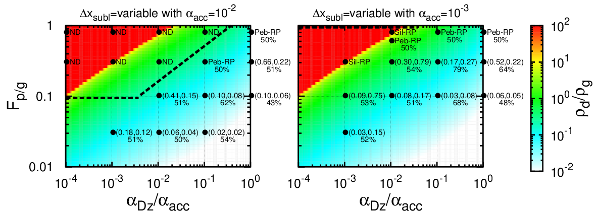
Figure 5 shows the maximum midplane solid-to-gas ratio around the water snow line in the ––(=) space. The background color contours correspond to the results obtained for silicate dust inside the snow line in Paper I. The red-colored area indicates runaway pile-up of silicate dust (i.e., no steady-state and an indication of planetesimal formation via direct gravitational collapse). The dependence on is discussed in Appendix C.
Points in Fig. 5 represent the results of our 1D simulations. The left and right numbers in the parenthesis represent the maximum (pebbles) and (silicate dust), respectively. When a runaway pile-up occurs in our 1D simulations, it is labeled either by ”Peb-RP” for pebbles or by ”Sil-RP” for silicate dust. The numbers below the parenthesis in Fig. 5 show the rock fraction in pebbles. For a combination of a small (=)/ and a large as an initial setting (as we set pebbles initially exist only at the outer boundary), pebbles do not drift from the outer boundary as a consequence of continuous slowing down of the radial drift velocity of pebbles due to Drift-BKR (we label these parameters by ”ND” as the ”no-drift” region in Fig. 5 – see also Section 4.2).
In the following subsections, we discuss the comparison to previous works (Section 5.1), the detailed processes of pile-up of silicate dust (Section 5.2), that of pebbles (Section 5.3), runaway pile-ups of pebbles and silicate dust (Section 5.4), rock-to-ice ratio within the pile-up region (Section 5.5), and implication for planet formation (Section 5.6).
5.1 Comparison to previous works
In most previous studies of the pile-up of silicate dust and pebbles around the snow line, was assumed (Dra̧żkowska & Alibert 2017; Schoonenberg & Ormel 2017). Figure 5 indicates that such parameters do not lead to a runaway pile-up of silicate dust inside the snow line, while a pile-up of pebbles outside the snow line could satisfy a condition for SI to take place for sufficiently large pebble mass flux of (Fig. 5). Previous studies (Dra̧żkowska & Alibert 2017; Schoonenberg & Ormel 2017) assumed and a runaway pile-up of pebbles was not reported (only a steady-state is reached with for ), while it could take place when with Drift-BKR (Hyodo et al. 2019, see also).
5.2 Pile-up of silicate dust inside the snow line
As discussed in Paper I, silicate dust can pile up just inside the snow line (Estrada et al. 2016; Ida & Guillot 2016; Schoonenberg & Ormel 2017; Dra̧żkowska & Alibert 2017; Hyodo et al. 2019; Gárate et al. 2020, Fig. 1; see also). Our 1D simulations include the recycling process via sticking of the diffused dust onto icy pebbles beyond the snow line. It conserves the inward mass flux of silicate dust across the snow line (all the diffused silicate dust eventually comes back to the snow line with pebbles), which indicates (here, is the silicate fraction in the original pebbles at the outer boundary) is independent on and . The vertically integrated metallicity of silicate dust can be written as and is independent on as . The midplane solid-to-gas ratio is written as (). At the snow line, is regulated by (see Eq. (36) for ). Thus, both and cases have almost the same for the same and when (the right numbers in the parenthesis in Fig. 5)55 5 When , the back-reaction changes other quantities, such as the scale height of pebbles (Eq. (35))..
Our 1D simulations (the right numbers in the parenthesis in Fig. 5) and the results of an analytical formula that is calibrated by the Monte Carlo simulations (a color contour in Fig. 5 obtained from Paper I) show good consistency when pebble pile-up is not significant. Paper I neglected the recycling of water vapor onto pebbles, but it does not significantly affect the pile-up of silicate dust inside the snow line as the mass flux of silicate dust is a critical parameter for the pile-up.
5.3 Pile-up of pebbles outside the snow line
In this subsection, we discuss how pebbles pile up just outside the snow line and its dependence on . Outside the snow line, the pile-up of icy pebbles is locally enhanced due to two distinct recycling processes: the recondensation of water vapor and sticking of silicate dust (Ida & Guillot 2016; Schoonenberg & Ormel 2017; Dra̧żkowska & Alibert 2017; Hyodo et al. 2019; Gárate et al. 2020, Fig. 1; see also). The efficiency of the recycling process (i.e., ) is a critical parameter to regulate the pile-up of icy pebbles. Thus, unlike the case of silicate dust (Section 5.2), the value is different for the same and at a different (see the left and right panels in Fig. 5).
The surface density of pebbles does not strongly depend on as pebbles are only partially coupled to the gas flow (Okuzumi et al. 2012; Ida & Guillot 2016, ;) and the radial velocity of pebbles is mainly dominated by the gas drag (the first term in Eq. (17)), while the surface density of the gas becomes smaller for larger as . This indicates that is when the recycling processes are negligible.
As increases or/and decreases, the pile-up of pebbles tends to increase as the disk metallicity increases () and the scale height of pebbles decreases (Eqs. (35) and (36)). However, when , an efficient recycling of water vapor and dust onto pebbles can change this dependence for some parameters (for example, the cases of ). Comparing the maximum and , the pile-up of pebbles is more significant than that of silicate dust when is sufficiently large and when the diffusion is an efficient process (i.e., cases) because the recycling of the vapor and the dust onto pebbles efficiently enhances the pile-up of pebbles (Hyodo et al. 2019). The pile-up of silicate dust is more prominent when the diffusivity is weak (i.e., cases).
5.4 Conditions for preferential pile-up of silicate dust versus pebbles
Finally, we aim to understand under which conditions the runaway pile-ups of silicate dust or/and pebbles are favored around the snow line.
The black lines in Fig. 5 indicate where pebbles cannot drift toward the snow line, corresponding to the ND region (see Section 4.2; au and are used here). In the case of , the red-colored region is located above the black line, which implies that parameters in the space that would yield the runaway pile-up of silicate dust found in Paper I in fact lie in the forbidden ND region. On the other hand, for , the pile-up of silicate dust inside the snow line for and found Paper I is outside of the ND region and confirmed by our simulations.
Generally, runaway pile-ups around the snow line occur over a broader range of parameters for than for . Runaway pile-up of silicate dust is favored for a small (labeled by ”Sil-RP”), while runaway pile-up of pebbles (labeled by ”Peb-RP”) only occurs for a limited range of parameters (large and ).
The results in Fig. 5 thus indicate that planetesimal formation around the snow line potentially occurs via a direct gravitational collapse of solids, to form icy or rocky planetesimal inside or outside the snow line, respectively, depending on the parameters of and . However, the formation efficiencies of these two kinds of planetesimals strongly depend on the disk conditions. This emphasizes that detailed disk evolution models including a realistic treatment of pebble growth are required to understand planetesimal formation around the snow line.
5.5 Rock-to-ice ratio within the pile-up region
Around the snow line, the rock-to-ice mixing ratio can be modified due to sublimation, condensation, and the recycling effects (Hyodo et al. 2019). Our numerical simulations show that pebbles just outside the snow line contain both ice and rock (the numbers below parenthesis in Fig. 5 indicate resulting rock fractions). The results indicate that cases tend to most efficiently increase the rock fraction from the original value (the 1:1 initial rock-ice ratio; Section 2) for a fixed .
For a higher , the scale height of silicate dust becomes larger (Eq. (36)), which leads to a less efficient sticking of silicate dust onto icy pebbles (its efficiency ), leading to a lower rock fraction in pebbles. However, a higher yields a more efficient outward diffusion of silicate dust released in the inner region, leading to a higher surface density of silicate dust outside the snow line, hence enhancing the silicate fraction in pebbles (the sticking efficiency ).
Diff-BKR and Drift-BKR also play critical roles as these effects modify the diffusivity and radial motion of solids. As a result of a combination of these different effects, the numerical results show that the rock fraction in pebbles, generally increases from the initial value of wt% up to wt%, depending on and (Fig. 5). When a runaway pile-up of pebbles occurs (labeled by Peb-RP in Fig. 5), the rock fraction becomes wt%. This is because the runaway pile-up occurs by accreting pebbles that drift from the outer region.
Thus, forming planetesimals from pebbles (by GI or SI) by runaway pile-up outside the snow line leads to a rock fraction being similar to that of the original pebbles formed in the outer region. The threshold for the occurrence of a streaming instability should be close to unity, within an order of magnitude (Carrera et al. 2015; Yang et al. 2017). As shown in Fig. 5, lower values of this threshold could lead to the formation of rock-rich planetesimals even from the pile-up of pebbles outside of the ice line. This is for example the case for and . This may explain the high dust-to-ice ratio measured in comet 67P (O’Rourke et al. 2020). Planetesimals formed from the pile-up of silicate dust inside of the snow line should be purely rocky.
5.6 Implication for planet formation
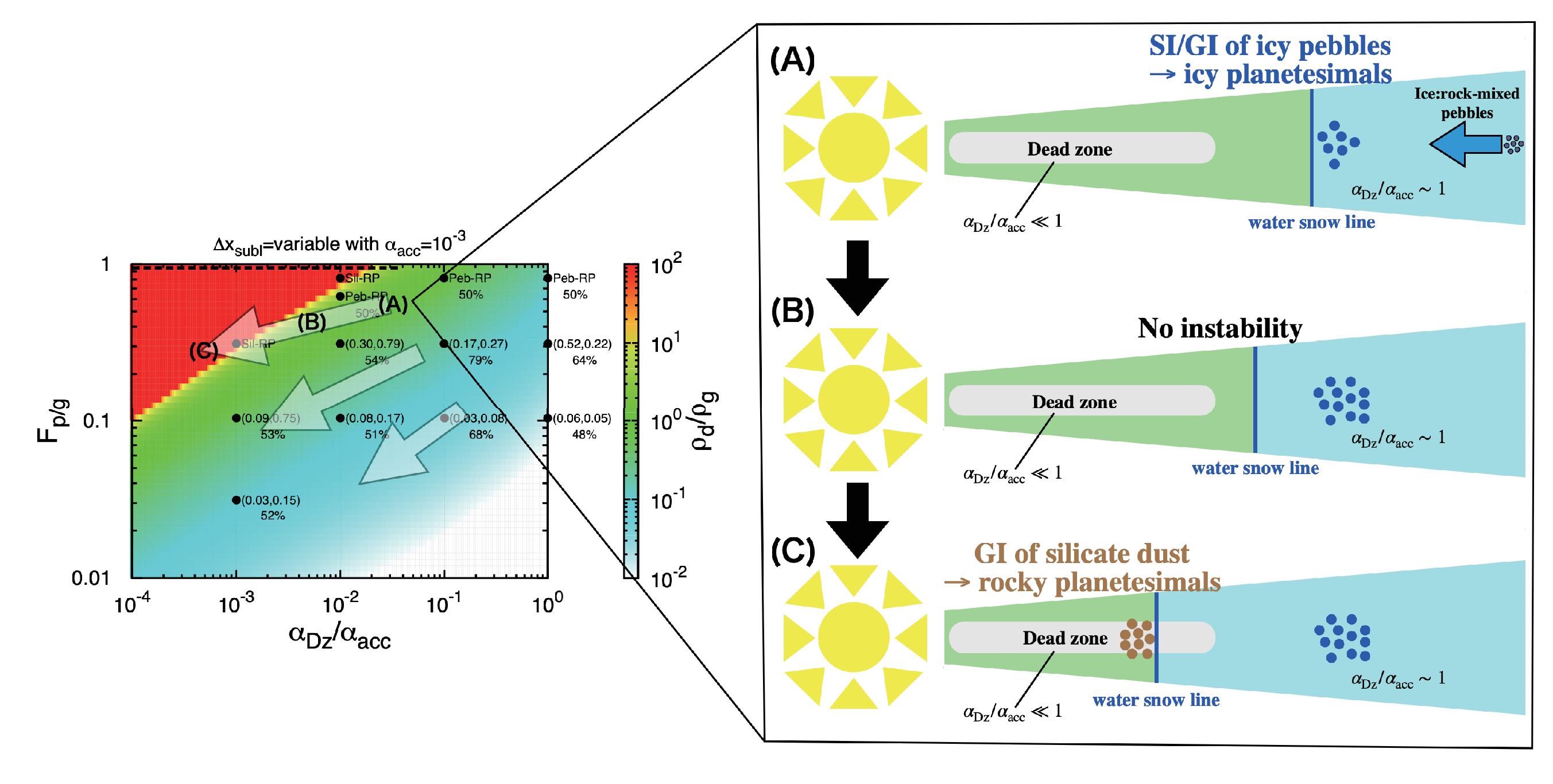
The structure and evolution of protoplanetary disks remain poorly constrained. We propose with Fig. 6 an example scenario that would lead to the formation of both ice-rich and rock-rich planetesimals as seen in the solar system.
The evolution of the disks is characterized by a decrease of the accretion rate, a decrease of viscous heating and therefore an inward migration of the snow line (Oka et al. 2011). In the same time, could decrease (Ida et al. 2016). The inner region of the disk may have an MRI-inactive ”dead zone” near the disk midplane where turbulence and correspondingly diffusion are weak (Gammie 1996, Fig. 6;). The radial boundary between the active zone in the outer disk region () and the dead zone in the inner disk region () may smoothly change, that is, may gradually become smaller as the distance to the central star becomes smaller (Bai et al. 2016; Mori et al. 2017, e.g.,).
Our results (see Fig. 5) imply that in the early stage of the disk evolution when the snow line is located in the active outer region, a pile-up of icy pebbles leading to the formation of icy planetesimals by GI or SI may take place. As shown in Fig. 6, late in the evolution, the migration of the snow line into the dead inner region would lead to the formation of rocky planetesimals. In-between, in an intermediate phase, the planetesimal formation around the snow line would be suppressed because of a combination of and that are insufficient to lead to a pile-up of solids in the disk midplane.
As the observed structure and theoretically modeled evolutionary paths of protoplanetary disks are diverse, following a distinct evolutionary path in the ––– space as well as that of the snow line could produce a diversity of the outcomes of the planetesimal formation around the snow line. A preferential formation of planetesimals only around the snow line would produce a localized narrow ring distribution of planetesimals.
6 Summary
In this paper, to study the pile-up of solids around the snow line, we incorporated a realistic (obtained from Paper I) and the KH-instability-considered (Section 4.1), for the first time, into a 1D diffusion-advection code that includes the back-reactions to radial drift and diffusion of icy pebbles and silicate dust. The code takes into account ice sublimation, the release of silicate dust, and their recycling through the recondensation and sticking onto pebbles. We studied a much wider range of disk parameters (in the ) space) than previous studies. Our main findings are as follows.
First, we derived the sublimation width of drifting icy pebbles, a critical parameter to regulate the scale height of silicate dust (Section 3). We also derived the scale height of pebbles, including the effects of KH instabilities (Section 4.1).
Second, using analytical arguments, we identified a parameter regime in the space, in which pebbles cannot reach the snow line by stopping their radial drift due to Drift-BKR in a self-induced manner (the ”no-drift” region; Section 4.2).
Third, our 1D simulations showed that case is more favorable for the pile-up of solids around the snow line than that for . The ”no-drift” regime entirely covers parameter space of the runaway pile-up of silicate dust when case (left panel in Fig. 5), preventing a runaway pile-up of silicate dust inside the snow line. In contrast, in the case, large values are allowed and could lead to a runaway pile-up of silicate dust inside the snow line (right panel in Fig. 5). In the case of , both silicate dust and pebbles could experience runaway pile-ups inside and outside the snow line, forming rocky and icy planetesimals, respectively.
Forth, pebbles just outside the snow line is a rock-ice mixture (Section 5.5). When a runaway pile-up of pebbles occurs just outside the snow line, the local rock-to-ice ratio becomes similar to that of pebbles formed at the outer region – i.e., the resultant planetesimal composition would be water-bearing materials, if planetesimals ultimately formed from such pebbles. In contrast, almost pure rocky planetesimals formed from silicate dust, if GI occurs inside the snow line.
Lastly, we discussed the implication of the runaway pile-ups around the snow line to planet formation (Section 5.6). A diversity of outcomes in terms of planetesimal formation around the snow line would occur for a diversity of protoplanetary disks. Detailed prescriptions of disk evolution and pebble growth are necessary.
Acknowledgements.
We thank Dr. Chao-Chin Yang for discussions. We thank Dr. Beibei Liu for his constructive comments that improved the manuscript. RH was supported by JSPS Kakenhi JP17J01269 and 18K13600. RH also acknowledges JAXA’s International Top Young program. TG was partially supported by a JSPS Long Term Fellowship at the University of Tokyo. SI was supported by MEXT Kakenhi 18H05438. SO was supported by JSPS Kakenhi 19K03926 and 20H01948. ANY was supported by NASA Astrophysics Theory Grant NNX17AK59G and NSF grant AST-1616929.References
- Armitage et al. (2013) Armitage, P. J., Simon, J. B., & Martin, R. G. 2013, ApJ, 778, L14
- Bai & Stone (2013) Bai, X.-N. & Stone, J. M. 2013, ApJ, 769, 76
- Bai et al. (2016) Bai, X.-N., Ye, J., Goodman, J., & Yuan, F. 2016, ApJ, 818, 152
- Blum & Wurm (2000) Blum, J. & Wurm, G. 2000, Icarus, 143, 138
- Carrera et al. (2015) Carrera, D., Johansen, A., & Davies, M. B. 2015, A&A, 579, A43
- Charnoz et al. (2019) Charnoz, S., Pignatale, F. C., Hyodo, R., et al. 2019, A&A, 627, A50
- Chiang (2008) Chiang, E. 2008, ApJ, 675, 1549
- Chiang & Youdin (2010) Chiang, E. & Youdin, A. N. 2010, Annual Review of Earth and Planetary Sciences, 38, 493
- Ciesla & Cuzzi (2006) Ciesla, F. J. & Cuzzi, J. N. 2006, Icarus, 181, 178
- Desch et al. (2017) Desch, S. J., Estrada, P. R., Kalyaan, A., & Cuzzi, J. N. 2017, ApJ, 840, 86
- Dra̧żkowska & Alibert (2017) Dra̧żkowska, J. & Alibert, Y. 2017, A&A, 608, A92
- Dubrulle et al. (1995) Dubrulle, B., Morfill, G., & Sterzik, M. 1995, Icarus, 114, 237
- Estrada et al. (2016) Estrada, P. R., Cuzzi, J. N., & Morgan, D. A. 2016, ApJ, 818, 200
- Gammie (1996) Gammie, C. F. 1996, ApJ, 457, 355
- Gárate et al. (2020) Gárate, M., Birnstiel, T., Drążkowska, J., & Stammler, S. M. 2020, A&A, 635, A149
- Gerbig et al. (2020) Gerbig, K., Murray-Clay, R. A., Klahr, H., & Baehr, H. 2020, ApJ, 895, 91
- Goldreich & Ward (1973) Goldreich, P. & Ward, W. R. 1973, ApJ, 183, 1051
- Gonzalez et al. (2017) Gonzalez, J. F., Laibe, G., & Maddison, S. T. 2017, MNRAS, 467, 1984
- Gressel et al. (2015) Gressel, O., Turner, N. J., Nelson, R. P., & McNally, C. P. 2015, ApJ, 801, 84
- Gundlach et al. (2018) Gundlach, B., Schmidt, K. P., Kreuzig, C., et al. 2018, MNRAS, 479, 1273
- Hasegawa et al. (2017) Hasegawa, Y., Okuzumi, S., Flock, M., & Turner, N. J. 2017, ApJ, 845, 31
- Hyodo et al. (2019) Hyodo, R., Ida, S., & Charnoz, S. 2019, A&A, 629, A90
- Hyodo et al. (2021) Hyodo, R., Ida, S., & Guillot, T. 2021, A&A Letters, doi:10.1051/0004-6361/202040031
- Ida & Guillot (2016) Ida, S. & Guillot, T. 2016, A&A, 596, L3
- Ida et al. (2021) Ida, S., Guillot, T., Hyodo, R., Okuzumi, S., & Youdin, A. N. 2021, arXiv e-prints, arXiv:2011.13164
- Ida et al. (2016) Ida, S., Guillot, T., & Morbidelli, A. 2016, A&A, 591, A72
- Kanagawa et al. (2017) Kanagawa, K. D., Ueda, T., Muto, T., & Okuzumi, S. 2017, ApJ, 844, 142
- Kimura et al. (2015) Kimura, H., Wada, K., Senshu, H., & Kobayashi, H. 2015, ApJ, 812, 67
- Lichtenegger & Komle (1991) Lichtenegger, H. I. M. & Komle, N. I. 1991, Icarus, 90, 319
- Liu et al. (2019) Liu, B., Lambrechts, M., Johansen, A., & Liu, F. 2019, A&A, 632, A7
- Lynden-Bell & Pringle (1974) Lynden-Bell, D. & Pringle, J. E. 1974, MNRAS, 168, 603
- Morbidelli et al. (2015) Morbidelli, A., Lambrechts, M., Jacobson, S., & Bitsch, B. 2015, Icarus, 258, 418
- Mori et al. (2017) Mori, S., Muranushi, T., Okuzumi, S., & Inutsuka, S.-i. 2017, ApJ, 849, 86
- Musiolik & Wurm (2019) Musiolik, G. & Wurm, G. 2019, ApJ, 873, 58
- Oka et al. (2011) Oka, A., Nakamoto, T., & Ida, S. 2011, ApJ, 738, 141
- Okuzumi et al. (2016) Okuzumi, S., Momose, M., Sirono, S.-i., Kobayashi, H., & Tanaka, H. 2016, ApJ, 821, 82
- Okuzumi et al. (2012) Okuzumi, S., Tanaka, H., Kobayashi, H., & Wada, K. 2012, ApJ, 752, 106
- O’Rourke et al. (2020) O’Rourke, L., Heinisch, P., Blum, J., et al. 2020, Nature, 586, 697
- Ros et al. (2019) Ros, K., Johansen, A., Riipinen, I., & Schlesinger, D. 2019, A&A, 629, A65
- Saito & Sirono (2011) Saito, E. & Sirono, S.-i. 2011, ApJ, 728, 20
- Schoonenberg & Ormel (2017) Schoonenberg, D. & Ormel, C. W. 2017, A&A, 602, A21
- Sekiya (1998) Sekiya, M. 1998, Icarus, 133, 298
- Shakura & Sunyaev (1973) Shakura, N. I. & Sunyaev, R. A. 1973, A&A, 24, 337
- Simon et al. (2015) Simon, J. B., Lesur, G., Kunz, M. W., & Armitage, P. J. 2015, MNRAS, 454, 1117
- Steinpilz et al. (2019) Steinpilz, T., Teiser, J., & Wurm, G. 2019, ApJ, 874, 60
- Wada et al. (2011) Wada, K., Tanaka, H., Suyama, T., Kimura, H., & Yamamoto, T. 2011, ApJ, 737, 36
- Yang et al. (2017) Yang, C. C., Johansen, A., & Carrera, D. 2017, A&A, 606, A80
- Yang et al. (2018) Yang, C.-C., Mac Low, M.-M., & Johansen, A. 2018, ApJ, 868, 27
- Youdin & Goodman (2005) Youdin, A. N. & Goodman, J. 2005, ApJ, 620, 459
- Youdin & Lithwick (2007) Youdin, A. N. & Lithwick, Y. 2007, Icarus, 192, 588
- Youdin & Shu (2002) Youdin, A. N. & Shu, F. H. 2002, ApJ, 580, 494
- Zhu et al. (2015) Zhu, Z., Stone, J. M., & Bai, X.-N. 2015, ApJ, 801, 81
Appendix A Dependence of dust pile-up upon
Silicate dust is released during the sublimation of the drifting icy pebbles approaching the snow line. Different works have adopted different models of the scale height of silicate dust in a 1D-radial accretion disk (Ida & Guillot 2016; Schoonenberg & Ormel 2017; Hyodo et al. 2019, e.g.,). The midplane density of silicate dust inside the snow line is calculated by , which is also used to describe the strength of the back-reaction of the gas onto their motion (e.g., Eq. (18)). Therefore, the description of is critical for the back-reaction and to evaluate the pile-up of dust in the midplane. In this section, we demonstrate how different models of affect the dust pile-up inside the snow line.
Ida & Guillot 2016 neglected the effects of the vertical stirring of the released dust and assumed that the dust keeps the same scale height as that of pebbles, that is, , where is the scale height of pebbles at the snow line. In contrast, Schoonenberg & Ormel 2017 assumed that the released silicate dust is instantaneously stirred to the vertical direction and has the same scale height as that of the gas, that is, .
Because silicate dust is released from sublimating pebbles, Hyodo et al. 2019 modeled that the released silicate dust has the same scale height as that of pebbles at the snow line and is gradually stirred to the vertical direction as a function to the distance to the snow line as
| (100) |
where a notation of ”snow” indicates values at the snow line. . is the diffusion/mixing timescale to the vertical direction at the snow line and is the mean free path of turbulent blobs. and are calculated by using the physical values at the snow line and we use .
Fig. 7 shows different models of the scale height of silicate dust and their resultant pile-ups of silicate dust, including a more realistic model used in this work (Equation (36) which is originally derived in Paper I).
The model of Schoonenberg & Ormel 2017, , underestimated pile-up of silicate dust when , while it correctly evaluated when . Ida & Guillot 2016, , overestimated the pile-up of silicate dust regardless of the value of . Hyodo et al. 2019 overestimated pile-up of silicate dust near the snow line.

Appendix B Particle size and Stokes number

The Stokes number of a particle depends on the local gas structure and is written by using the stopping time as . The stopping time represents the relaxation timescale of particle momentum through the gas drag. Here, we consider two regimes of the stopping time and is given as
| (101) | ||||
| (102) |
where is the thermal velocity, is the particle radius, and g cm-3 is the particle internal density, and is the gas spatial density, respectively. The mean free path of the gas is given as
| (103) |
where cm2 is the collisional cross section of the gas molecules. We note that depends on the local gas structure and is a function of .
Rewriting Eqs. (101) and (102) give particle sizes in the Epstein and Stokes regimes for a fixed . Fig. 8 shows critical particle sizes of for different and particle sizes in either Epstein and Stokes regimes for a fixed . Because , , , , and , the particle size in the Epstein regime becomes , that is, for (the gray lines in Fig. 8). Because , the particle size in the Stokes regime becomes , which is independent on , that is, for (the black lines in Fig. 8).
Appendix C Dependence on the sublimation width
Here, we discuss the dependence on the sublimation width . The detailed derivation of the sublimation width is discussed in Section 3. In Fig. 5, a realistic variable sublimation width is used (Eq. (77)). In contrast, Fig. 9 is the same as Fig. 5 but the sublimation width is fixed ().
As the sublimation width becomes larger, the average scale height of silicate dust becomes larger because the silicate dust released in a wider radial width diffuses vertically and radially mixes (Eq. (36)), leading to a lower concentration of silicate dust in the disk midplane. This effect is more significant for small (i.e., the advection-dominated regime) as both radial and vertical mixings are ineffective, while large (i.e., the diffusion-dominated regime) case is rarely affected because the mixing effects ”erase” the information of the initial distribution of silicate dust. Thus, the parameter space for runaway pile-up of silicate dust is reduced for small in the case of a variable (Eq. (77)) compared to the case of the fixed (compare Fig. 9 to Fig. 5).
