a]Department of Physics, California Institute of Technology, Pasadena, California 91125, USA b]School of Physics and Astronomy, Cardiff University, Cardiff, CF24 3AA, United Kingdom c]SLAC National Accelerator Laboratory, 2575 Sand Hill Road, Menlo Park, CA 94025 d]Kavli Institute for Particle Astrophysics and Cosmology, Stanford University, 452 Lomita Mall, Stanford, CA 94305 e]Department of Physics and Astronomy, University of British Columbia, Vancouver, British Columbia, V6T 1Z1, Canada f]Center for Astrophysics, Harvard & Smithsonian, Cambridge, MA 02138, U.S.A g]Department of Physics, University of Cincinnati, Cincinnati, Ohio 45221, USA h]Jet Propulsion Laboratory, Pasadena, California 91109, USA i]Kavli Institute for Cosmological Physics, University of Chicago, Chicago, IL 60637, USA j]Department of Physics, Harvard University, Cambridge, MA 02138, USA k]Minnesota Institute for Astrophysics, University of Minnesota, Minneapolis, 55455, USA l]National Institute of Standards and Technology, Boulder, Colorado 80305, USA m]School of Physics and Astronomy, University of Minnesota, Minneapolis, 55455, USA n]Department of Physics, Stanford University, 382 Via Pueblo Mall, Stanford, CA 94305 o]Service des Basses Températures, Commissariat à lEnergie Atomique, 38054 Grenoble, France p]Department of Physics, University of Illinois at Urbana-Champaign, Urbana, Illinois 61801 q]Department of Astronomy, University of Illinois at Urbana-Champaign, Urbana, Illinois 61801, USA r]Department of Applied Mathematics and Theoretical Physics, University of Cambridge, Cambridge CB3 0WA, UK s]Department of Physics, Enrico Fermi Institute, University of Chicago, Chicago, IL 60637
Receiver development for BICEP Array, a next-generation CMB polarimeter at the South Pole
Abstract
A detection of curl-type (-mode) polarization of the primary CMB would be direct evidence for the inflationary paradigm of the origin of the Universe. The Bicep/Keck Array (BK) program targets the degree angular scales, where the power from primordial -mode polarization is expected to peak, with ever-increasing sensitivity and has published the most stringent constraints on inflation to date. Bicep Array (BA) is the Stage-3 instrument of the BK program and will comprise four Bicep3-class receivers observing at 30/40, 95, 150 and 220/270 GHz with a combined 32,000+ detectors; such wide frequency coverage is necessary for control of the Galactic foregrounds, which also produce degree-scale -mode signal. The 30/40 GHz receiver is designed to constrain the synchrotron foreground and has begun observing at the South Pole in early 2020. By the end of a 3-year observing campaign, the full Bicep Array instrument is projected to reach between 0.002 and 0.004, depending on foreground complexity and degree of removal of -modes due to gravitational lensing (delensing). This paper presents an overview of the design, measured on-sky performance and calibration of the first BA receiver. We also give a preview of the added complexity in the time-domain multiplexed readout of the 7,776-detector 150 GHz receiver.
keywords
Cosmic Microwave Background, Polarization, Instrumentation, Cosmology, B-Modes, Inflation1 Introduction
Measurements of the polarization of the Cosmic Microwave Background (CMB) provide crucial information to further our understanding of the early Universe. The Lambda cold dark matter (CDM) model predicts an -mode polarization pattern in the CMB at the level of a few K as well as a -mode polarization signal arising from gravitational lensing of -modes by the large-scale structure of the Universe. Inflationary gravitational waves are predicted to produce an excess of -mode power on degree angular scales that is scaled by the tensor-to-scalar ratio . The value of is directly tied to the energy scale of inflation [1]. While certain classes of inflation models predict extremely small values of , a detection of primordial -mode polarization would be direct evidence for the theory of inflation. However, polarized Galactic dust and synchrotron foregrounds hamper our ability to measure primordial gravitational waves and need to be disentangled from the degree-scale -mode polarization signal by observing the sky at multiple frequencies with exquisite sensitivity. Additionally, the removal of -mode power due to gravitational lensing (delensing) can lead to improved constraints on , but it requires higher resolution observations [2].
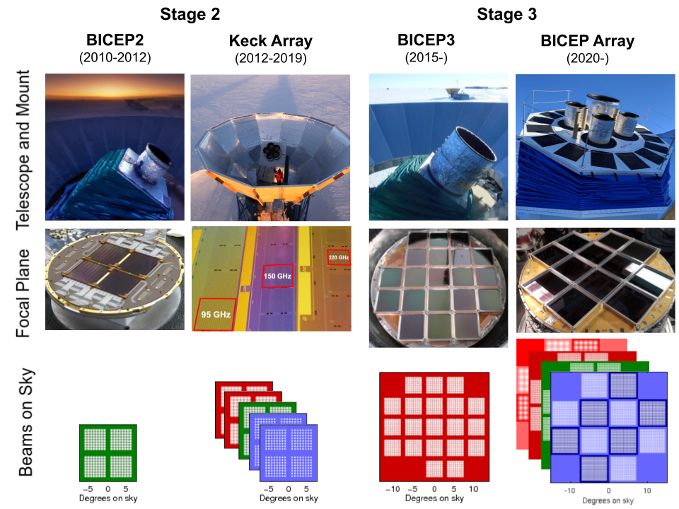
The most stringent published constraint on the tensor-to-scalar ratio is at 95% confidence from Bicep/Keck Array data in conjunction with Planck and WMAP measurements [4] (see Figure 1, which includes the most recent Planck points [3]). Over the past 15 years, our experimental strategy of designing small-aperture, cryogenic, refracting wide-field telescopes observing from the South Pole has proven successful in probing the degree-scale polarization of the CMB (multipoles 35 l 300) with tight control of systematic errors. Bicep1 was the first polarimeter designed specifically to target the -mode signal and operated from January 2006 through December 2008 with 49 orthogonal pairs of polarization-sensitive NTD bolometers observing at 100 and 150 GHz. Bicep2 observed the sky with 500 antenna-coupled transition-edge sensor (TES) bolometers at 150 GHz from 2010 to 2012, and reported an excess of -mode power over the base lensed-CDM model in the range [5], which was later attributed to polarized dust emission [6]. The Keck Array consisted of five Bicep2 -like 260 mm aperture receivers and started observations at 150 GHz in 2012. The interchangeable Keck Array receivers allowed us to diversify the frequency coverage over the years: 95 GHz receivers were deployed in 2014, 220 GHz in 2015, and 270 GHz in 2017. The higher-throughput Bicep3 receiver replaced Bicep2 in its mount in 2015, with a 520 mm aperture and 2500 detectors all operating at 95 GHz for an on-sky instantaneous instrument sensitivity of 6.7 [7]. Figure 2 shows the progression of the Bicep/Keck Array program, to larger apertures, larger focal planes, and wider frequency coverage.
| Receiver | Nominal | Nominal Single | Beam | Survey Weight |
| Observing Band | Number of | Detector NET | FWHM | Per Year |
| (GHz) | Detectors | () | (arcmin) | ()-2 yr-1 |
| Keck Array | ||||
| 95 | 288 | 288 | 43 | 24,000 |
| 150 | 512 | 313 | 30 | 30,000 |
| 220 | 512 | 746 | 21 | 2,750 |
| 270 | 512 | 1,310 | 17 | 800 |
| Bicep3 | ||||
| 95 | 2,560 | 265 | 24 | 240,000 |
| Bicep Array | ||||
2 The Bicep Array Instrument
The latest instrument in our program is Bicep Array [8, 9], which adopts the same interchangeable concept used in Keck Array and is comprised of four Bicep3-class receivers in six frequency bands spanning from 30 to 270 GHz (Figure 3), which are all 27% wide. The lowest (30/40 GHz) and highest (220/270 GHz) frequency receivers are dual-band receivers each featuring a checker-board of focal plane modules with single-band detectors centered at the two adjacent bands (Figure 2). Splitting the atmospheric windows this way provides more spectral information on the Galactic synchrotron and dust emission, thus improving the constraints on the foreground model parameters. Scaling from previous on-sky performance, Table 1 shows the expected sensitivities and survey weights11 1 Survey Weight is a single number representing the total raw experimental sensitivity achieved, and is defined as where is the map area and is the noise level in the maps. Survey weight is useful because it scales linearly with integration time, number of detectors, and statistical sensitivity to [10]. of the 4 receivers, which amount to 32,000+ photon-noise limited polarization-sensitive detectors.
At the end of 2019, the Keck Array telescope mount has been replaced by the new Bicep Array mount [11], which provides bore-sight rotation about the optical axis, in addition to rotation in Azimuth and Elevation, following the Keck Array and Bicep3 designs. During the same Austral Summer, we also deployed the first 30/40 GHz Bicep Array receiver, equipped with a full complement of detector modules to fill the focal plane, which has now observed for an entire season. The other Bicep Array receivers will be installed in the new mount with a staged approach over the next few years22 2 Due to the COVID-19 pandemic, no crew will deploy at the end of 2020 and the instrument will remain unchanged.. In the meantime, we are continuing observations with a subset of the Keck Array receivers installed in open slots until they are filled by available Bicep Array receivers. The observations will continue to focus on the deep Bicep/Keck Array sky patch so that the new low-frequency data can be combined with existing multi-frequency observations. An updated project timeline is shown in Figure 12.
2.1 Receiver Overview
Bicep Array is largely based on the successful design of Bicep3[12, 13, 14, 15]. Each receiver is housed in a custom-designed vacuum cryostat [11] 2.1 m tall and 0.9 m in diameter (excluding the additional envelopes of the multi-channel readout electronics and the pulse-tube cooler). Figure 4 shows a cross-section of the receiver, along with the optical diagram for reference. The vacuum and 50 K shells are designed with a short base-stage, and long cylinders for the main section, which allow users to lift off the outer shells from the base plate without undoing the cabling, thermal joints and sub-Kelvin truss structure. The vacuum window is made out of HDPE for the 30/40 GHz receiver, while thinner solutions for the higher frequencies are actively being pursued [16].
The 4 K shell is divided into two lengthwise segments for ease of access during integration; the top optics section houses the objective lens and baffle rings designed to minimize reflections within the tube. The lower optics section holds the nylon filter and the field lens. The 4 K plate supports the fridge space and the sub-kelvin thermo-mechanical truss structure. The 50 K volume is supported by G-10 truss legs, providing robust structural support while maintaining low thermal conductivity between temperature stages. The truss legs for the 4 K and sub-Kelvin structures are instead made out of carbon fiber, owing to its superior room-temperature elastic modulus to low-temperature thermal conductivity ratio at K[17].

2.2 Thermal Architecture
All Bicep Array receivers (see Figure 4) use a Cryomech PT41533 3 https://www.cryomech.com/products/pt415/ pulse tube with nominal cooling capacity of 40 W and 1.5 W at the 50 K and 4 K stages, respectively. The pulse tube is driven by a remote stepper motor that is physically detached and electrically/mechanically isolated from the cold head. Residual mechanical vibrations induced by the fittings connecting the head and the motor are damped by a spring bellows connecting the cold head to the cryostat shell. We also use e-beam welded heat straps with flexible sections of ropelay stranded copper in order to minimize the rigidity and the transmission of vibration to the cryostat stages.
The optical filtering follows the successful Bicep3 scheme [12]. Behind the 560 mm-aperture vacuum window, which lets W of thermal radiation into the receiver, a stack of 12 1/8”-thick layers of Zotefoam HD-3044 4 https://www.zotefoams.com/wp-content/uploads/2016/02/HD30-December-2017.pdf with 1/10” spacers provides infrared filtering [18, 19], in conjunction with a 10 mm-thick IR-absorptive alumina filter[20], which is installed at the top of the 50 K stage. The lower 4 K optics section holds an absorptive 7.45 mm-thick nylon filter, to prevent any short-wavelength radiation let through by the alumina filter above from reaching the focal plane. Finally a low-pass metal-mesh filter [21, 22] installed at 300 mK defines the upper edge of the band.
Combining measurements with a thermal model, the total loading on the 50 K and 4 K stages with the receiver on-sky is estimated to be about 40 W and 0.5 W, respectively. Table 5 reports the median Bicep Array system temperatures during CMB observations in 2020.
Sub-Kelvin cooling for the detectors is provided by a three-stage helium (4He/3He/3He) sorption fridge from CEA Grenoble[23], with heat intercepts at 2 K (4He stage), 300 mK (intermediate cooler, or IC), and 250 mK (ultra cooler, or UC). With a design total loading of 70 and 15 W at the 300 and 250 mK stages, respectively, the fridge has sufficient cooling capacity to maintain a 3-day uninterrupted observing schedule between thermal cycles. With the telescope on-sky during observations, we have achieved a minimum fridge hold time of 2.5 days, after which other scheduling constraints become relevant.
The sub-Kelvin structure is located on top of the 4 K base plate, above the sorption fridge. It is separated into three thermal, “wedding-cake” carbon-fiber truss stages at 2 K, 300 mK, and 280 mK. Each stage provides radiative shielding and room for cable heat-sinking to the respective fridge stages, allowing low-loading environment for the focal plane and detectors. The detector modules and copper focal plane plate are heat-sunk to the fridge UC stage via a flexible high-purity copper-foil heat strap. The strap connects to the focal plane through a stainless steel block. The temperature of the strap is actively regulated, and the block serves as a passive low-pass thermal filter to attenuate thermal noise from the control circuit. The estimated conductive loading on the 2 K, IC, and UC stages is 178, 55, and 0.234 W, respectively, from heat-sinking of cables and the mechanical truss structure, but not including radiative contributions (see Table 2).
| Truss structure conducted load budget | |||
|---|---|---|---|
| 2 K (W) | 300 mK (W) | 250 mK (nW) | |
| 18 100-way NbTi cables (TDM) | 84.1 | 18.8 | 82.2 |
| 4 25-way Manganin cables (HK) | 1.9 | 0.5 | 2.8 |
| Cernox cables (HK) | 6.6 | 1.2 | 2.4 |
| Heater cables (HK) | 2.8 | 0.5 | 1.8 |
| Carbon fiber trusses (M) | 33.6 | 12.9 | 47.1 |
| Aluminized mylar RF shield (M) | 48.7 | 21.5 | 97.8 |
| Total | 177.7 | 55.5 | 234.1 |
2.3 Optics
Following the same concept as in previous small-aperture telescopes in the Bicep/Keck Array series, the Bicep Array receivers are simple diffraction-limited two-lens refractors, which provide a telecentric and flat focal surface with minimum aberrations over a wide field of view (see Figure 4 for the optical diagram). The telescope has a mean -ratio of /1.57 at the center of the focal plane, which has a diameter of 475.8 mm. The HDPE lenses are 650 mm in diameter, with a clear aperture of 550 mm and a field of view of 29.6 degrees. The lenses and nylon filter are cooled to 4 K to minimize loading on the detectors and are anti-reflection coated to minimize in-band reflections. The 4 K space between the objective and the field lens is lined with baffle rings coated with Eccosorb® HR-10 microwave absorber to suppress far-sidelobes reflections. The same Eccosorb® is also used to define the 550 mm optical stop for the system, which is located just above (sky side) the objective lens. The detector beams are designed to terminate on the cold stop with an edge taper ranging from -10 to -13 dB with respect to the main lobe, depending on the frequency. Following the approach of previous optical designs in the Bicep/Keck Array telescope series, we take advantage of the excellent directivity provided by the uniform illumination of the planar phased-array antennas and maintain a conservative edge taper at the aperture stop [26].
The current material for the vacuum window is 1”-thick HDPE at 30/40 GHz, where HDPE has negligible in-band emission. At higher frequencies, thinner windows are being pursued, which will reduce the in-band optical loading and thereby significantly improve mapping speed[16].
2.4 Detector Modules and Readout
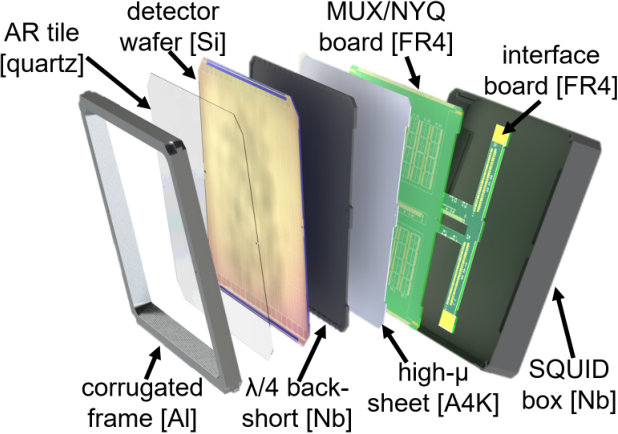
The Bicep Array receivers are equipped with state-of-the-art dual-polarization antenna-coupled TES arrays, fabricated on 150 mm diameter silicon wafers [27, 26]. The detector arrays are based on planar in-phase combined slot antennas that provide higher pixel packing density than feedhorns, given a chosen edge taper 55 5 See https://cmb-s4.org/wiki/images/2019_10_16_CMBS4_DetectorTechUpdate_V01.pdf#page=6.. The readout architecture is based on Time-Domain Multiplexing (TDM [28, 29]), developed by the University of British Columbia and NIST, with two stages of SQUIDs driven using a Multi-Channel Electronics (MCE) system that provides SQUID/TES bias voltages, controls SQUID addressing, and digitizes detector signals. The readout chain is based on numerous previous successful experiments [30, 31], with the detector modules at 280 mK carrying the first-stage SQUIDs on a PCB located behind the /4 backshort (see Figure 5), which then connect to a custom focal plane distribution board and through superconducting NbTi wires to a stage of Series Array SQUIDs at 4 K (see Figure 6). In the design of these PCBs and the architecture of the cables, we paid particular attention to pairing signal and return in order to minimize cross-talk among channels. Moreover, the SQUIDs and TES detectors are carefully shielded from sources of magnetic fields, including the Earth’s field (see Section 2.5 for more details).
Twelve detector modules are tiled onto the focal plane, each containing 32 to 2048 detectors, depending on the observing frequency (see Table 1). The module is based on the successful Bicep3 design[14], except the detectors are now fabricated on 6” silicon wafers, instead of the previous 4” wafers to expedite lithographic fabrication with higher detector count per module. The first-stage SQUID readout multiplexing chips are housed in a FR4 circuit board inside the module with superconducting tin-copper traces (Bicep3 and Bicep Array 30/40 GHz used aluminum traces on alumina substrates instead). The housing is constructed with superconducting niobium and aluminum, which, along with a high- A4K sheet inside the module, are designed to achieve high magnetic shielding performance (Section 2.5). Figure 5 shows the exploded view of the module design at 150 GHz.

Electromagnetic interactions between the edge antennas and the metal frame around the module can cause polarized beam mismatch on the edge pixels, resulting in potential temperature-to-polarization leakage in the CMB maps. We designed corrugated walls to minimize this effect. The 30/40 GHz module implements a novel broadband corrugation design that mitigates the differential ellipticity caused by the metal frame over 57% bandwidth, from 25 GHz to 45 GHz [32, 33].
The first 30/40 GHz receiver (BA1) in its final configuration will be populated with 6 modules at each frequency in a checker-board arrangement. The design for the two frequencies is similar, with appropriate dimensions of the antenna scaled accordingly to frequency [34]. Due to the COVID-19 pandemic, no crew will deploy at the end of 2020 and the instrument will observe the sky for two full seasons in the configuration it was first deployed at the end of 2019, with the following breakdown of modules: 4 at 30 GHz, 7 at 40 GHz, plus one prototype dual-band 30/40 GHz module with 16 dichroic optical pixels (64 detectors; Shiu et al. in prep. 66 6 https://microdevices.jpl.nasa.gov/interactivepdfs/index.html?pdf=2020-MDL-Annual-report.pdf, page 61.).
The design of the two Bicep Array receivers at 95 and 150 GHz is at an advanced level of development and is based on the same TDM architecture and TES detector arrays. Table 3 shows the multiplexing factors and cabling arrangement for each receiver. We are currently in the process of validating the 150 GHz module design, which allows an 18x18 pixel tile (see Figure 5) to be read out. The large number of MCEs needed at 150 GHz required a relatively minor mechanical redesign of the MCE boxes in order to fit within the space constraints imposed by the telescope mount. In the context of CMB-S4 [19], our team has developed ambitious preliminary designs of TDM modules that can read up to 1,920 detectors, without requiring superconducting flex cables.
The last Bicep Array receiver at 220/270 GHz will eventually feature over 20,000 detectors, and will be read out using RF-multiplexing schemes, which promise higher multiplexing factors than TDM. One possible implementation is the microwave SQUID readout (Mux [35]) system that has been already been operated with our current TES detectors for a year as an on-sky demonstrator[36]. In this system, the TES detectors are unchanged and are multiplexed by coupling each TES to its own superconducting microwave resonator through an RF-SQUID. Alternatively, Thermal Kinetic Inductance Detectors (TKID [37, 38]) offer on-wafer RF multiplexing to greatly simplify wafer hybridization, and are currently being developed and tested within the collaboration.
| Frequency | 30/40 GHz | 95 GHz | 150 GHz |
|---|---|---|---|
| # Detector Tiles | 12 | 12 | 12 |
| # Detectors | 192 + 300 | 4,056 | 7,776 |
| # Detectors/Tile | 32 + 50 | 288 | 648 |
| # SQUID MUX11 chips/Tile | 6 | 32 | 64 |
| # MCE | 1 | 3 | 6 |
| # Columns/MCE | 24 | 32 | 32 |
| # Rows (multiplexing factor) | 33 | 43 | 41 |
| # SQUID series array (SSA) modules | 4 | 12 | 24 |
| # Manganin cables (300 K - 4 K) | 5 | 15 | 30 |
| # NbTi cables (4 K - 280 mK) | 3 | 9 | 18 |

2.5 Magnetic Shielding
The SQUID/TES readout system is known to be susceptible to external magnetic fields[39, 40] and Bicep Array’s magnetic shielding architecture is designed to minimize the level of spurious signals generated as the telescope moves along the Earth’s magnetic field lines. We studied multiple configurations using COMSOL Multi-Physics software [41], which allowed us to simulate the Meissner behavior of a superconducting material (see Figure 7). We selected an architecture with a 1 mm-thick cylindrical A4K high magnetic permeability () sheet wrapped around the 50 K cryostat shell, combined with a 2 mm-thick Niobium superconductive flared cup at 300 mK, which provide a shielding factor of 200 or better at the focal plane. Slotted mounting holes on the 50 K shield allow sufficient thermal expansion mismatch between the aluminum and A4K. The sub-Kelvin Niobium shield required a continuous base in addition to the flared cylinder to enhance the shielding performance. The Niobium base is not electrically connected to the copper base plate to avoid potential superconductor-metal interactions at the contact surface.
The TESs and the SQUIDs are then further shielded inside the focal plane modules, each of which features a superconducting aluminum detector frame, a superconducting Niobium SQUID box and a 0.020”-thick sheet of high- A4K material to provide a combined shielding factor of about 500 or better. Simulation shows the biggest field leakage comes from the slots for the readout cables. An additional Niobium sheet (not shown in Figure 7 for simplicity), with cable slots that are offset with respect to those in the SQUID box, is mounted on the back side of the module Niobium housing to minimize the leakage. Table 4 shows the simulated magnetic shielding performance of the receiver and module, listed separately. The combined system shielding performance is less straightforward to simulate due to interaction among the shields, and is beyond the scope of this paper.
We have performed direct measurements of the system to validate the COMSOL simulations by applying an external field that is modulated at a known frequency, including the use of cryogenic flux gate sensors installed at the location of the SQUIDs and TES. The results of these measurements will be published in a dedicated study (Schillaci, Basu Thakur et al, in prep.)

| Parts | Axial Residual Flux | Transverse Residual Flux |
|---|---|---|
| 50K and 4K shields (combined) | 0.24% | 0.52% |
| Detector module (as a whole) | 0.12% | 0.20% |
2.6 RF Shielding
Following the successful electromagnetic interference (EMI) mitigation strategy of previous small-aperture telescopes in the Bicep/Keck Array series [42], the detectors and SQUID readout chain are enclosed in a radio frequency (RF) shield. The RF shield begins on the top of the focal plane plate and extends down to the 4 K insert volume. Circular clamps at each temperature stage hold an aluminized Mylar shroud that drapes over the “wedding-cake” truss structure (a photo showing this has been published in a previous conference proceeding [9]). The continuous Mylar sheet is used to create a conductive path that surrounds the stages at different temperatures without thermally linking them (see Table 2 for an estimate of the thermal loading due to the Mylar). The ring on the stage at the bottom of the truss connects to the aluminum walls of the fridge volume and the 4 K base plate, which then connects to the optics tube. Filter connectors (micro-D saver PI filtered, model no. C48-00063-01 77 7 https://portal.cristek.com/admin/client-data/cristek-web-links/cwl_links/4/FILTRevD.PDF) at the 4 K base plate protect the cold electronics from RF interference picked up in wiring outside the cryostat.
3 BICEP Array 30/40 GHz Receiver Performance
The 30/40 GHz BA1 cryostat was successfully integrated with the new Bicep Array mount and cooled to base temperatures in January 2020. Table 5 reports the median system temperatures in BA1 during CMB observations in 2020, demonstrating adequate cryogenic performance achieved already during the first season. The exact focal plane configuration that was deployed is described in Section 2.4 and will remain unchanged for two full observing seasons due to the COVID-19 pandemic.
An extensive detector calibration campaign was conducted over the first several months of 2020, by a combination of the Austral Summer crew and winter-over Nathan Precup. Figure 8 shows FTS spectra for all the single-band detectors in BA1, demonstrating well-behaved band-passes at both frequencies and high end-to-end optical efficiency from the combination of detectors and optical train.
Another major check of the optical system is provided by taking beam maps with a source in the far-field of the telescope [43, 44]. Figure 9 shows band-averaged far-field beam map (FFBM) composites, obtained by coadding all per-detector FFBM composites in a frequency band (not including the prototype dual-band detectors mentioned in Section 2.4). Per-detector FFBM composites are made by coadding all individual FFBMs for a detector, which are taken at different boresight angles. The band-averaged composites demonstrate in-focus imaging and FWHM beam sizes in line with the design values of 76 and 57 arcmin at 30 and 40 GHz, respectively (see Table 1).
Finally, Figure 10 shows a preliminary Bicep Array 40 GHz temperature map covering 570 deg2, obtained from 3,187 50-minute scansets from the 2020 observing season, and compared to the Planck 44 GHz[45] reobserved temperature map. Besides the variable [46] QSO [HB89] 0208-512 88 8 https://ned.ipac.caltech.edu/byname?objname=[HB89]%200208-512 visible at [RA, Dec] = [32.6925, -51.0172] deg in the Bicep Array field, the maps look very similar. Further analysis is beyond the scope of this paper.
| Thermometer | Temperature (K) | Thermometer | Temperature (K) |
| 50 K pulse tube head | 41.803 | 4 K heat strap cold side | 3.562 |
| 50 K heat strap cold side | 43.664 | 4 K heat strap warm side | 3.689 |
| 50 K heat strap warm side | 49.036 | Fridge bracket | 3.943 |
| 50 K plate | 50.251 | Field lens | 4.434 |
| 50 K tube bottom | 58.737 | Nylon filter | 4.896 |
| 50 K tube top | 63.268 | Objective lens | 5.183 |
| 50 K alumina filter | 63.624 | SQUID Series Array (SSA) board | 4.002 |
| He-4 switch | 22.154 | 2 K plate | 2.457 |
| He-3 switch | 23.191 | Niobium cup (flared section) | 0.373 |
| He-4 pump | 5.006 | IC heat strap | 0.322 |
| He-3 pump | 4.895 | IC plate | 0.321 |
| He-4 condenser | 3.781 | Edge filter | 0.321 |
| He-4 evaporator | 2.492 | UC plate side | 0.303 |
| Intercooler (IC) evaporator | 0.318 | UC plate center | 0.302 |
| Ultracooler (UC) evaporator | 0.274 | UC heat strap | 0.279 |


4 Observing Strategy and Projected Sensitivity
Bicep Array focuses its CMB observations on the same sky patch as Bicep3, spanning right ascension RA and declination , with an effective area of (larger than Keck Array’s , but colocated). With the full Bicep Array sensitivity (see Figure 11), we expect to achieve and surpass the Planck map depths at all frequencies after only a few months of observations.
The parameters of the Keck Array, Bicep3, and Bicep Array are given in Table 1. The Bicep Array sensitivity estimates are based on achieved survey weight per year of the Keck Array. This procedure accounts for all real-world observing imperfections such as detector yield, cryogenic efficiency, data cuts, ground subtraction, temporal filtering, and other unexpected events that decrease the final sensitivity compared to the ideal case. Figure 12 shows the projected sensitivity of the ongoing and planned Bicep program. We expected to reach at the end of the program, depending on the level of delensing that can be achieved using higher-resolution data from the South Pole Telescope. A demonstration of the delensing technique was just published [47].

Acknowledgements.
Bicep/Keck Array project (including Bicep2 Bicep3 and Bicep Array) have been made possible through a series of grants from the National Science Foundation (including 0742818, 0742592, 1044978, 1110087, 1145172, 1145143, 1145248, 1639040, 1638957, 1638978, 1638970, 1726917, 1313010, 1313062, 1313158, 1313287, 0960243, 1836010, 1056465, 1255358) and by the Keck Foundation. The development of antenna-coupled detector technology was supported by the JPL Research and Technology Development Fund and NASA Grants 06-ARPA206-0040, 10-SAT10-0017, 12-SAT12-0031, 14-SAT14-0009, 16-SAT16-0002, & 18-SAT18-0017. The development and testing of focal planes were supported by the Gordon and Betty Moore Foundation at Caltech. Readout electronics were supported by a Canada Foundation for Innovation grant to UBC. The computations in this paper were run on the Odyssey cluster supported by the FAS Science Division Research Computing Group at Harvard University. The analysis effort at Stanford and SLAC was partially supported by the Department of Energy, Contract DE-AC02-76SF00515. We thank the staff of the U.S. Antarctic Program and in particular the South Pole Station without whose help this research would not have been possible. Tireless administrative support was provided by Kathy Deniston, Sheri Stoll, Irene Coyle, Donna Hernandez, and Dana Volponi.References
- [1] Kamionkowski, M. & Kovetz, E. D., “The quest for b modes from inflationary gravitational waves,” Annual Review of Astronomy and Astrophysics 54, 227–269 (2016).
- [2] Smith, K. M., Hanson, D., LoVerde, M., Hirata, C. M., & Zahn, O., “Delensing CMB polarization with external datasets,” J. Cosmology Astropart. Phys 2012, 014 (June 2012).
- [3] Tristram, M., Banday, A. J., et al., “Planck constraints on the tensor-to-scalar ratio,” arXiv e-prints , 2010.01139 (Oct. 2020).
- [4] BICEP2 Collaboration, Keck Array Collaboration, et al., “Constraints on Primordial Gravitational Waves Using Planck, WMAP, and New BICEP2/Keck Observations through the 2015 Season,” Phys. Rev. Lett. 121, 221301 (Nov. 2018).
- [5] Ade, P. A., Aikin, R. W., et al., “Detection of b-mode polarization at degree angular scales by bicep2,” Physical Review Letters 112(24), 241101 (2014).
- [6] BICEP2/Keck and Planck Collaborations, Ade, P. A. R., et al., “Joint Analysis of BICEP2/Keck Array and Planck Data,” Phys. Rev. Lett. 114, 101301 [BK13] (Mar. 2015).
- [7] Kang, J. H., Ade, P. A. R., et al., “2017 upgrade and performance of BICEP3: a 95GHz refracting telescope for degree-scale CMB polarization,” Society of Photo-Optical Instrumentation Engineers (SPIE) Conference Series 10708, 107082N (July 2018).
- [8] Hui, H., Ade, P. A. R., et al., “BICEP Array: a multi-frequency degree-scale CMB polarimeter,” Society of Photo-Optical Instrumentation Engineers (SPIE) Conference Series 10708, 1070807 (July 2018).
- [9] Schillaci, A., Ade, P. A. R., et al., “Design and Performance of the First BICEP Array Receiver,” Journal of Low Temperature Physics 199, 976–984 (Feb. 2020).
- [10] The CMB-S4 Collaboration, :, et al., “CMB-S4: Forecasting Constraints on Primordial Gravitational Waves,” arXiv e-prints , 2008.12619 (Aug. 2020).
- [11] Crumrine, M., Ade, P. A. R., et al., “BICEP Array cryostat and mount design,” Society of Photo-Optical Instrumentation Engineers (SPIE) Conference Series 10708, 107082D (July 2018).
- [12] Ahmed, Z., Amiri, M., et al., “BICEP3: a 95GHz refracting telescope for degree-scale CMB polarization,” Society of Photo-Optical Instrumentation Engineers (SPIE) Conference Series 9153, 91531N (Aug. 2014).
- [13] Grayson, J. A., Ade, P. A. R., et al., “BICEP3 performance overview and planned Keck Array upgrade,” Society of Photo-Optical Instrumentation Engineers (SPIE) Conference Series 9914, 99140S (July 2016).
- [14] Hui, H., Ade, P. A. R., et al., “BICEP3 focal plane design and detector performance,” Society of Photo-Optical Instrumentation Engineers (SPIE) Conference Series 9914, 99140T (July 2016).
- [15] Wu, W. L. K., Ade, P. A. R., et al., “Initial Performance of Bicep3: A Degree Angular Scale 95 GHz Band Polarimeter,” Journal of Low Temperature Physics 184, 765–771 (Aug. 2016).
- [16] Barkats, D., Dierickx, M. I., et al., “Ultra-thin large-aperture vacuum windows for millimeter wavelengths receivers,” Society of Photo-Optical Instrumentation Engineers (SPIE) Conference Series 10708, 107082K (July 2018).
- [17] Runyan, M. C. & Jones, W. C., “Thermal conductivity of thermally-isolating polymeric and composite structural support materials between 0.3 and 4 K,” Cryogenics 48, 448–454 (Sept. 2008).
- [18] Choi, J., Ishitsuka, H., Mima, S., Oguri, S., Takahashi, K., & Tajima, O., “Radio-transparent multi-layer insulation for radiowave receivers,” Review of Scientific Instruments 84, 114502–114502–6 (Nov. 2013).
- [19] Abitbol, M. H., Ahmed, Z., et al., “CMB-S4 Technology Book, First Edition,” arXiv e-prints , 1706.02464 (June 2017).
- [20] Inoue, Y., Matsumura, T., Hazumi, M., Lee, A. T., Okamura, T., Suzuki, A., Tomaru, T., & Yamaguchi, H., “Cryogenic infrared filter made of alumina for use at millimeter wavelength,” Appl. Opt. 53, 1727–1733 (Mar 2014).
- [21] Ade, P. A. R., Pisano, G., Tucker, C., & Weaver, S., “A review of metal mesh filters,” Society of Photo-Optical Instrumentation Engineers (SPIE) Conference Series 6275, 62750U (June 2006).
- [22] Tucker, C. E. & Ade, P. A. R., “Thermal filtering for large aperture cryogenic detector arrays,” Society of Photo-Optical Instrumentation Engineers (SPIE) Conference Series 6275, 62750T (June 2006).
- [23] Duband, L., Prouve, T., Bock, J. J., Moncelsi, L., & Schillaci, A., “Sub-kelvin cooling for the bicep array project,” in [Cryocoolers 20 ], International Cryocooler Conference (2018). arXiv: 2009.09997.
- [24] Olson, J. R., “Thermal conductivity of some common cryostat materials between 0.05 and 2 K,” Cryogenics 33, 729–731 (Jan. 1993).
- [25] Woodcraft, A. L., Ventura, G., Martelli, V., & Holland, W. S., “Thermal conductance at mK temperatures of woven ribbon cable with phosphor-bronze clad superconducting wires,” Cryogenics 50(8), 465–468 (2010).
- [26] BICEP2 Collaboration, Keck Array Collaboration, et al., “Antenna-coupled TES Bolometers Used in BICEP2, Keck Array, and Spider,” Astrophys. J. 812, 176 (Oct. 2015).
- [27] Bonetti, J. A., Turner, A. D., et al., “Microfabrication and Device Parameter Testing of the Focal Plane Arrays for the Spider and BICEP2/Keck CMB Polarimeters,” in [13th International Workshop on Low Temperature Detectors - LTD13 ], American Institute of Physics Conference Series 1185, 367–370 (2009).
- [28] Battistelli, E. S., Amiri, M., et al., “Functional Description of Read-out Electronics for Time-Domain Multiplexed Bolometers for Millimeter and Sub-millimeter Astronomy,” Journal of Low Temperature Physics 151, 908–914 (May 2008).
- [29] Battistelli, E. S., Amiri, M., et al., “Automated SQUID tuning procedure for kilo-pixel arrays of TES bolometers on the Atacama Cosmology Telescope,” Society of Photo-Optical Instrumentation Engineers (SPIE) Conference Series 7020, 702028 (July 2008).
- [30] Bintley, D., MacIntosh, M. J., et al., “Characterising the SCUBA-2 superconducting bolometer arrays,” Society of Photo-Optical Instrumentation Engineers (SPIE) Conference Series 7741, 774106 (July 2010).
- [31] Henderson, S. W., Allison, R., et al., “Advanced ACTPol Cryogenic Detector Arrays and Readout,” Journal of Low Temperature Physics 184, 772–779 (Aug. 2016).
- [32] Soliman, A., Ade, P. A. R., et al., “Design and performance of wide-band corrugated walls for the BICEP Array detector modules at 30/40 GHz,” Society of Photo-Optical Instrumentation Engineers (SPIE) Conference Series 10708, 107082G (July 2018).
- [33] Soliman, A., Ade, P. A. R., et al., “Optical Design and Characterization of 40-GHz Detector and Module for the BICEP Array,” Journal of Low Temperature Physics 199, 1118–1126 (Feb. 2020).
- [34] Zhang, C., Ade, P. A. R., et al., “Characterizing the Sensitivity of 40 GHz TES Bolometers for BICEP Array,” Journal of Low Temperature Physics 199, 968–975 (Feb. 2020).
- [35] Henderson, S. W., Ahmed, Z., et al., “Highly-multiplexed microwave SQUID readout using the SLAC Microresonator Radio Frequency (SMuRF) electronics for future CMB and sub-millimeter surveys,” Society of Photo-Optical Instrumentation Engineers (SPIE) Conference Series 10708, 1070819 (July 2018).
- [36] Cukierman, A., Ahmed, Z., et al., “Microwave Multiplexing on the Keck Array,” Journal of Low Temperature Physics 199, 858–866 (May 2020).
- [37] Wandui, A., Bock, J. J., et al., “Thermal kinetic inductance detectors for millimeter-wave detection,” Journal of Applied Physics 128, 044508 (July 2020).
- [38] Minutolo, L., Steinbach, B., Wandui, A., & O’Brient, R., “A Flexible GPU-Accelerated Radio-frequency Readout for Superconducting Detectors,” IEEE Transactions on Applied Superconductivity 29, 2912027 (Aug. 2019).
- [39] Claycomb, J. R. & Miller, J. H., “Superconducting magnetic shields for squid applications,” Review of Scientific Instruments 70(12), 4562–4568 (1999).
- [40] Vavagiakis, E. M., Henderson, S. W., et al., “Magnetic sensitivity of AlMn TESes and shielding considerations for next-generation CMB surveys,” Journal of Low Temperature Physics 193(3-4), 288–297 (2018).
- [41] Bergen, A., van Weers, H. J., et al., “Design and validation of a large-format transition edge sensor array magnetic shielding system for space application,” Review of Scientific Instruments 87(10), 105109 (2016).
- [42] BICEP2 Collaboration, Ade, P. A. R., et al., “BICEP2. II. Experiment and three-year Data Set,” Astrophys. J. 792, 62 (Sept. 2014).
- [43] BICEP2 Collaboration, Keck Array Collaboration, et al., “BICEP2/Keck Array XI: Beam Characterization and Temperature-to-Polarization Leakage in the BK15 Data Set,” Astrophys. J. 884, 114 (Oct. 2019).
- [44] St Germaine, T., Ade, P. A. R., et al., “Optical Characterization of the Keck Array and BICEP3 CMB Polarimeters from 2016 to 2019,” Journal of Low Temperature Physics 199, 824–832 (Feb. 2020).
- [45] Planck Collaboration, Ade, P. A. R., et al., “Planck 2015 results. VI. LFI mapmaking,” Astr. & Astroph. 594, A6 (Sept. 2016).
- [46] Fuhrmann, L., Larsson, S., et al., “Detection of significant cm to sub-mm band radio and -ray correlated variability in Fermi bright blazars,” Mon. Not. Roy. Astron. Soc. 441, 1899–1909 (July 2014).
- [47] BICEP/Keck, SPTpol Collaborations, et al., “A Demonstration of Improved Constraints on Primordial Gravitational Waves with Delensing,” arXiv e-prints , 2011.08163 (Nov. 2020).
- [48] BICEP2/Keck Collaborations, “Improved Constraints on Cosmology and Foregrounds from BICEP2 and Keck Array Cosmic Microwave Background Data with Inclusion of 95 GHz Band,” Phys. Rev. Lett. 116, 031302 [BK14] (Jan. 2016).
- [49] Bender, A. N., Anderson, A. J., et al., “On-Sky Performance of the SPT-3G Frequency-Domain Multiplexed Readout,” Journal of Low Temperature Physics 199, 182–191 (Apr. 2020).
- [50] “The South Pole Observatory (SPO).” https://docushare.wipac.wisc.edu/dsweb/Get/Version-104468/CMB%20Presentation%20for%20ICNO%20Meeting%2018-Mar-2020.pdf#page=25 (2020).