(Dated: December 2 2020)
Role of Modern Optical Techniques in Gravitational Wave Detection
Abstract
Gravitational waves were first proposed by Henri Poincaré in 1905 and were subsequently predicted by Albert Einstein in his General Theory of Relativity. In 2015, first Gravitational Waves signals were detected by LIGO of two black holes merging about 1.3 billion light-years away. The discovery opened a new window of astronomy. Currently, four laser interferometers are operating around the world, two American detectors which are located in Hanford and Livingston, one Italian detector (VIRGO) located at Pisa and an underground Japanese detector KAGRA. This paper describes the modern optical techniques that are being used and future planned techniques for gravitational wave detection.
I Introduction
Just like Maxwell’s equation describe the relationship between electric charge and electromagnetic field, the Einstein field equations describe the interaction between mass and space-time curvature. Gravitational Waves (GW) are time de-pendent vacuum solutions to the field equations just like the electromagnetic waves are time dependent vacuum solutions to Maxwell’s equations.
GW are a perturbation of the metric propagating in a Minkowski space-time. These are generally generated by rapidly accelerating large and compact masses, like merging black hole, spinning massive neutron stars, or supernovae explosions. When GW travel through space-time fabric, it compresses and stretches the fabric simultaneously (Fig.1). The effect of stretching and compressing can directly be observed by measuring the displacement between the two masses[1, 2].
The induced displacement is directly proportional to the amplitude of the gravitational wave. The amplitude of the gravitation wave can be estimated as:
| (1) |
Where G is Gravitational constant, c is the speed of light, is the asymmetry of the source, E is a fraction of mass-produced and r is distance[1].
If for example, we take a supernovae explosion at Virgo cluster (15 Mpc) in which energy equivalent to 10-4M⊙ is produced, produces gravitational waves of 100 Hz and the signal duration is 1 msec, the amplitude of the gravitational wave on earth will be .
For a detector of length 4km, we are looking for the length difference of:
| (2) |
which is 1000 times smaller than the diameter of a proton[3]. The LIGO interferometers use special interferometry techniques, state-of-the-art optics, highly stable lasers and multiple layers of vibration isolation, to meet the design sensitivity.

II Detector Description
II-A Bar Detectors
The first GW detector was built by an experimental physicist Joseph Weber at the University of Maryland in 1965. Weber used solid aluminium cylinders of size 2 meter long and 1 meter in diameter, which were suspended using steel wires. A passing GW would set these detectors into the resonant frequency of about 1660 Hz; they were just like tuning forks for detecting GW. Piezo-electric crystals were attached to these crystals to convert the vibrational energy of the bar to electrical signals[4].
These bars were kept inside an isolated vacuum chamber to prevent EM interaction and acoustic noise interference. The two fundamental noise for these detectors were thermal noise which was caused by thermal vibration of aluminium atoms and electronic noise due to amplifiers which were used to amplify the electronic signals from piezo-electric crystals.
By 1969, Weber thought that he might have detected GW and claimed many detections over the year. Many groups tried to replicate Weber’s experiment, but, they didn’t detect any signals Weber showed. The average amplitude of oscillation due to thermal oscillations were much larger than the oscillation amplitude of the GW.
Ultimately, his claims were discarded due to many reasons, including that the experiment was not reproducible.
II-B Michelson Interferometer
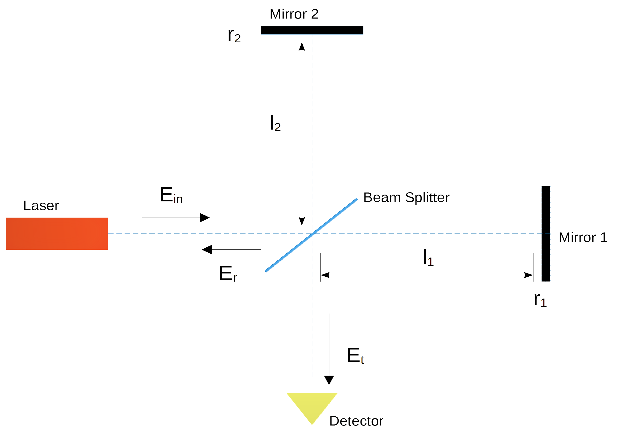
A Michelson Interferometer comprises of a laser source, beam splitter and two mirrors (Fig.2). Let the reflection coefficients of the mirrors be and , placed at a distance of and from beam splitter. The incident light at the beam splitter is represented as[5]:
| (3) |
The transmitted and reflected fields are related as:
| (4) |
| (5) |
where , , , , , represents phase acquired by beams in the arms, transmission coefficient, reflection coefficient, transmittance, and the reflectance of the beam splitter respectively.
The intensity of the fields is given by:
| (6) |
| (7) |
where is the intensity of the beam and is the phase difference of the two beams.
If we consider beam splitter and mirrors as test masses, the passing gravitational wave will cause the phase difference in two fields, thus showing interference at the output port. In other words, Michelson Interferometer (Fig.3) is sensitive to gravitational waves. This idea was originally developed by Rainer Weiss and Felix Pirani in 1967 and was further developed by Robert L. Forward.

II-C Frequency Response of Michelson Interferometer
The difference in phase of the two fields can be written as a sum[7, 8] of static phase() and effect due to passing GW():
| (8) |
| (9) |
Where and are frequency of GW and beam respectively, (,) is the frequency response function given as:
| (10) |
neglecting higher order terms (,) can be approximated as:
| (11) |
| (12) |
Taking maximum, therefore:
| (13) |
| (14) |
Thus, for example, we take a sinusoidal GW with a frequency of 500Hz, the length of arm required to detect is 150km!!
II-D Fabry-Perot Interferometer
As described in the previous section, the optimum length of the Michelson Interferometer arm to detect GW from astronomical sources is the order of 100km. However, this is unrealistic to build such a large detector on the surface of Earth due to current technological limitations. Therefore, to overcome this limitation, the optical paths length of the interferometer are folded by using the Fabry-Perot cavity.
A Fabry-Perot cavity consists of two partial reflective glass having a spacing between them. When light enters the cavity, it is partially transmitted from the first mirror, reflected multiple times inside the mirror, and then transmitted back again by the front mirror. The multiple reflections inside the cavity make the effective optical path length of light much larger than the length of the cavity[8].
Let us consider two mirrors placed parallel to each other at a distance of L. A plane wave of frequency and wavenumber k travelling in the z-direction is expressed as:
| (15) |

The reflection and transmission coefficients of mirrors are represented as (,) and (,). The reflected and transmitted light outside the cavity is expressed as:
| (16) |
| (17) |
where , ( for i=f,e), , and is the round trip phase of light inside the cavity. The reflection and transmission coefficients can be calculated as:
| (18) |
| (19) |
The Finesse () of a Fabry Perot interferometer is related to reflectivity of mirror as:
| (20) |
The Finesse () is also related to the number of round trips the light makes inside the cavity as:
| (21) |
Taking and , reflection and transmission coefficient can be approximated as:
| (22) |
| (23) |
where is the storage time, given as:
| (24) |
II-E Frequency Response of Fabry-Perot Interferometer
When GW passes, it changes the proper length of the cavity, thus affects the round trip phase of the light. Let be the delay of the wave which arrives at the first mirror after n round trips, therefore reflected field at the first mirror is[8]:
| (25) |
| (26) |
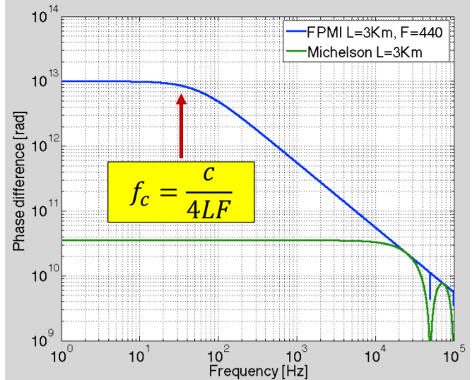
where is the response the function of the Fabry-Perot cavity. When the frequency of light is tuned to the resonance of the cavity i.e. , response function is given as:
| (27) |
The phase difference can be approximated as:
| (28) |
III Laser and sources of noise
One key technology necessary to reach the design sensitivity of these detectors is ultra-stable high power laser. The fundamental noise in the LIGO laser system is readout noise, and it is the only fundamental noise due to laser. The readout noise is the combination of shot noise and pressure noise.
III-A Shot noise
The shot noise arises due to random occurrences of photons on the detector. To measure the power of light is the same thing to count the number of photons in a time unit. The random occurrences can be modelled as Poisson distribution. The shot noise on the cavity is given as:
| (29) |
where is the input power, l is the length of the interferometer, is the wavelength of the input light and T(f)=d(/)/d is the unit-less transfer function of the interferometer. The shot noise is inversely proportional to input power and directly proportional to wavelength. Using high power lasers, shot noise can be minimized. The choice of wavelength cannot be arbitrary since high power laser devices are not available at all wavelengths. Currently, LIGO uses Nd:YAG lasers, with the wavelength of 1064nm. These are industrial grade lasers capable of producing a continuous wave of 100’s of Watts.
III-B Pressure noise
The pressure noise is due to pressure applied by photons on the mirrors. It is given as:
| (30) |
The pressure noise increases when the power of the laser increases, and it is high at low frequency. The total readout noise is:
| (31) |
Thus it is necessary to choose the right power of laser which gives minimum at the particular frequency[10].
III-C Pre-stabilized laser
The pre-stabilized laser (PSL) of the LIGO detectors is developed by the Laser Zentrum, Albert-Einstein-Institute (AEI) and neoLASE in Hannover, Germany. The laser system consists of three stages. It is enclosed in a class 1000 clean-room. It is very important that the laser is in a clean environment as particles in the beam path and on optical components lead to scattering and thus a reduction in the beam quality.
III-C1 Stage 1
The first stage consists of the non-planar ring oscillator (NPRO Fig.6). This solid-state laser uses an Nd:YAG (neodymium-doped yttrium aluminium garnet) crystal (of size about 1cm) as the laser medium. The front surface of the crystal is a partially reflective dielectric coating, which is highly transmissive to the input light and also serves as the mirror of the resonator. On all other surfaces, total internal reflection occurs. The NPRO is pumped by a laser diode having wavelength of 808nm and delivers a single-frequency output power of 2W[11, 12, 13].


III-C2 Stage 2
The second stage consists of a single-pass amplifier having an output power of 35W. The laser from NPRO is sent to four Nd:YVO4 crystals (Fig. 7). Each laser material is pumped by a 400 m diameter fibre-coupled laser diodes delivering a maximum output power of 45 W. To separate pump light from input light, a dichroic 45∘ mirror with anti-reflection coating for the pump wavelength and high-reflection coating for the laser wavelength is used[16]. 95 of the output power is within TEM00 mode.
III-C3 Stage 3
The third stage consists of a rod-shaped device called High Power Oscillator (HPO). The beam is made to pass through four bundles of fibre containing seven fibres each, which are arranged in a hexagonal pattern. Each fibre carries 45W power, therefore each bundle gives theoretical power of 315W. By the time beam leaves the oscillator, its power reaches around 200W. The frequency of the output beam is matched to the output of NPRO using series of loop controls, which results in ultra-stable frequency laser.

IV Power Recycling
IV-A Principle of power recycling
One of the fundamental noise which limits the sensitivity of the interferometer is shot noise. As previously seen, shot noise is inversely proportional to the square root of the incident power. Since the gravitational wave signal is proportional to the incident power, the shot-noise level of an interferometer is improved with high laser power.
Besides increasing the laser power, shot noise can also be improved by a technique called Power Recycling. In order to decrease the shot noise, the interferometer is operated in the dark fringe condition, i.e. the reflected beams from the arms are made to interfere destructively at the output port. In this case, the injected laser beam is almost reflected back to the laser source. In this technique, the reflected laser beam is made to reflect back to the interferometer by keeping a partially transmitting mirror (called power recycling mirror) between laser source and interferometer, which results in the increase of power inside the interferometer[18].
IV-B Recycling cavity
The additional cavity which is formed due to this recycling mirror is called Recycling cavity[19]. Let’s consider a recycling cavity (Fig. 9) formed by keeping mirror (PR; for simplicity, assume only one recycling mirror is kept). The fields are given as:
| (32) |
| (33) |
| (34) |
where , , , , , is the incident light, transmitted light, circulated light inside the cavity, transmission coefficient, reflection coefficient of recycling mirror and complex reflectivity of the entire mirrors of the Fabry-Perot cavity. From the above equations, we obtain the following expressions:
| (35) |
| (36) |
where g and rrec is the recycling cavity amplitude gain and reflectivity of the recycling cavity, respectively. The incident beam resonates with the recycling cavity when rcom is a real and positive number.

IV-C Power recycling gain
Power recycling gain or a power recycling factor (G) is the ratio of the laser power on the beamsplitter with and without the recycling mirror, which is given as:
| (37) |
When G>1, the effective power of the laser source increases to GP and the shot noise is reduced to the factor of . The typical power recycling gain expected for the LIGO detector is between 30 and 50. The power recycling gain is maximized when the reflectivity of the recycling mirror is equal to the reflectivity of the compound mirror i.e.[18]:
| (38) |

V Future
V-A Space based interferometers
Currently, LIGO has one of the largest vacuum systems on Earth; it takes 40 days of constant pumping to make an ideal operating pressure. Creating such a large vacuum is one of the current technological limitations. To overcome this, space based interferometer are planned.
One of the future planned space GW detector is the Laser Interferometer Space Antenna (LISA) jointly planned by ESA and NASA. In contrast to ground-based GW detectors that have a typical sensitivity in the range from 1Hz to 1kHz, the sensitivity for LISA stretches between 0.1mHz and 0.1Hz.

LISA comprises of 3 spacecraft in a heliocentric orbit, forming an equilateral triangle with a side of 2.5 million kilometres (Fig. 11). Each spacecraft has two test masses, kept in a free-fall condition; they form the reference points for interferometric measurement of the inter spacecraft distance. To measure the distance between two spacecraft, a 2W laser beam of 1064nm is sent through a 40cm Cassegrain telescope. The telescope receives and transmits the laser beam at the same time. In an ordinary interferometer, the received light from another spacecraft is sent back where the light would combine with the local oscillator to complete the measurement.
However, due to the large distance between the spacecraft, this method is not feasible. Due to diffraction, the transmitted laser beam widens to many kilometres at the receiving spacecraft; the received power is the order of few picowatts[22, 23].
In the LISA satellites, a transponder scheme with offset phase-locking is used. The received light is combined with a local oscillator derived from the transmitting laser, and the phase difference is measured. The laser beam is sent to the third spacecraft; the phase of the laser beam is the exact copy of the received laser light. The GW signal is calculated by measuring the phase and receiving time of each spacecraft[24].
V-B Atom interferometery
Apart from shot noise and pressure noise, the sensitivity of ground detectors is greatly limited due to seismic noise. These noises are generally caused due to ground vibrations, wind, human activities such as logging or trains, ocean waves, etc. The sensitivity of current ground Laser Interferometers at frequencies below 40Hz is poor because of this noise.
The GW spectrum between 10 Hz and 10-3 Hz has very exciting sources. GW emerging from sources such as white dwarf binaries, and intermediate and massive black holes occur in this band. This band is also interesting for the search for stochastic GW searches[25].
In an atom interferometer wave character of atoms is unlike photons. Just like laser interferometers, an atom is forced to follow a superposition of two spatially and temporally separated free-fall paths. The atom is coherently split using pulses of light which transfers momentum to a part of the atom. When this atom is combined later, it shows interference due to phase accumulated in these paths. Generally, this follows the Mach-Zehnder interferometer configuration. An atom interferometer consists of 3 stages: atom cloud preparation, interferometer pulse sequence, and detection.
V-B1 Stage 1
In the first stage, a sub-microkelvin cloud of atoms is formed using laser cooling. The basic principle of the laser cooling is that if an atom is travelling towards a laser and it absorbs the photon, it will be slowed down. The frequency of the laser is chosen to be somewhat higher than the atomic resonance. This stage is important because many systematic errors are sensitive to the initial condition of the atoms, so cooling mitigates these unwanted errors. At the end of the cooling stage, the final atom cloud has a very low density, which is enough to neglect the atom-atom interaction. This cloud is then launched with a velocity(vl) by transferring momentum using laser light.
V-B2 Stage 2
In the second stage, the atom cloud is made to follow a trajectory. A sequence of light pulses is used to steer these atoms (Fig. 11). These pulses serve as beam splitters and mirrors that coherently divide each atom’s wave-packet and then later recombine it to produce the interference. In an atom beamsplitter, laser light having wavevector k1 is initially absorbed by the atom. Subsequently, another laser light having wavevector k2 is made to strike atom, which stimulates the emission of a photon of wavevector k2. This results in a momentum transfer of:
| (39) |
The laser lights causes Rabi oscillations between states and states. When laser pulse time is equal to a quarter of a Rabi period (), it results in beamsplitter, and when laser pulse time is equal to the half of a Rabi period (), it results in a mirror. After the action of first beamsplitter pulse, the atom is in superposition state which differ in velocity by . This spatial difference of atom is proportional to the sensitivity of the interferometer towards the GW strain. A final beamsplitter pulse is applied to combine these two components, which results in interference.

V-B3 Stage 3
The third stage is atom detection. At the end of the second beamsplitter pulse, each atom is in a superposition of the two output velocity states which differ by . After an appropriate drift time, the two states are resolved separately and measured using absorption imaging. The total phase difference can be approximated as[25]:
| (40) |
where h, k2, xi and D are GW strain, the wavevector of the second laser, distance between atom and second laser, and distance between laser respectively.
The current challenge in this application is to cool the atom to the required narrow velocity distribution and support high repetition rate. On earth, the repetition rate of 10Hz is required for the GW band of 1-10Hz. Low-density cloud is required to mitigate the systematic error associated with cold atom collisions.
VI References
References
- [1] Konstantinos. Kokkotas “Gravitational Wave Astronomy” In Reviews in Modern Astronomy Wiley-VCH Verlag GmbH & Co. KGaA, 2008, pp. 140–166 DOI: 10.1002/9783527622993.ch7
- [2] E. Calloni “Introduction to gravitational wave detection and Advanced Virgo Status and perspectives” In Nucl. Part. Phys. Proc. 291-293, 2017, pp. 127–133 DOI: 10.1016/j.nuclphysbps.2017.06.026
- [3] B Abbott et al. “LIGO: the Laser Interferometer Gravitational-Wave Observatory” In Reports on Progress in Physics 72.7 IOP Publishing, 2009, pp. 076901 DOI: 10.1088/0034-4885/72/7/076901
- [4] Odylio Aguiar “Past, present and future of the Resonant-Mass gravitational wave detectors” In Research in Astronomy and Astrophysics 11.1 IOP Publishing, 2010, pp. 1–42 DOI: 10.1088/1674-4527/11/1/001
- [5] Andreas Freise and Kenneth Strain “Interferometer Techniques for Gravitational-Wave Detection” In Living Reviews in Relativity 13.1 Springer ScienceBusiness Media LLC, 2010 DOI: 10.12942/lrr-2010-1
- [6] Giles Hammond, Stefan Hild and Matthew Pitkin “Advanced technologies for future ground-based, laser-interferometric gravitational wave detectors” In Journal of Modern Optics 61.sup1 Informa UK Limited, 2014, pp. S10–S45 DOI: 10.1080/09500340.2014.920934
- [7] Lee Finn “Response of interferometric gravitational wave detectors” In Physical Review D 79, 2008 DOI: 10.1103/PhysRevD.79.022002
- [8] Keita Kawabe “Development of a 3-meter Fabry-Perot-Michelson”, 1998
- [9] Alessandro Bertolini “The most precise distance measurement ever made”, 2017 URL: https://www.nikhef.nl/˜z66/ASML-26APR2018/Alessandro-Bertolini_2017.pdf
- [10] Rana Adhikari “Sensitivity and noise analysis of 4 km laser interferometric gravitational wave antennae”, 2006
- [11] Li-Wei Wei “High-power laser system for Advanced Virgo gravitational wave detector : coherently combined master oscillator fiber power amplifiers”, 2015
- [12] Maik Frede et al. “Fundamental mode, single-frequency laser amplifier for gravitational wave detectors” In Optics express 15, 2007, pp. 459–65 DOI: 10.1364/OE.15.000459
- [13] Jan Põld “Design, implementation and characterization of the advanced LIGO 200 W laser system”, 2014 DOI: 10.15488/8345
- [14] Duncan Liu “Diffractive Combiner of Single-Mode Pump Laser-Diode Beams”, 2007 URL: https://www.techbriefs.com/component/content/article/tb/supplements/ptb/briefs/11623#
- [15] Maik Frede et al. “Fundamental mode, single-frequency laser amplifier for gravitational wave detectors” In Opt. Express 15.2 OSA, 2007, pp. 459–465 DOI: 10.1364/OE.15.000459
- [16] Lutz Winkelmann et al. “Injection-locked single-frequency laser with an output power of 220 W” In Applied Physics B 102, 2011, pp. 529–538 DOI: 10.1007/s00340-011-4411-9
- [17] P Kwee et al. “Stabilized high-power laser system for the gravitational wave detector Advanced LIGO” In Optics express 20, 2012, pp. 10617–34 DOI: 10.1364/OE.20.010617
- [18] Kiwamu Izumi “Multi-Color Interferometry for Lock Acquisition of Laser Interferometric Gravitational-wave Detectors”, 2012
- [19] Ando Masaki “Power recycling for an interferometric gravitational wave detector”, 1998
- [20] J Aasi et al. “Advanced LIGO” In Classical and Quantum Gravity 32.7 IOP Publishing, 2015, pp. 074001 DOI: 10.1088/0264-9381/32/7/074001
- [21] Thilo Schuldt “An optical readout for the LISA gravitational reference sensor”, 2010
- [22] O Jennrich “LISA technology and instrumentation” In Classical and Quantum Gravity 26.15 IOP Publishing, 2009, pp. 153001 DOI: 10.1088/0264-9381/26/15/153001
- [23] William Folkner and David Seidel “Gravitational Wave Missions from LISA to Big Bang Observer”, 2005 DOI: 10.2514/6.2005-6711
- [24] Karsten Danzmann and the LISA “LISA: laser interferometer space antenna for gravitational wave measurements” In Classical and Quantum Gravity 13.11A IOP Publishing, 1996, pp. A247–A250 DOI: 10.1088/0264-9381/13/11a/033
- [25] Savas Dimopoulos et al. “Atomic gravitational wave interferometric sensor” In Physical Review D 78.12 American Physical Society (APS), 2008 DOI: 10.1103/physrevd.78.122002
- [26] Brynle Barrett et al. “Prospects for Precise Measurements with Echo Atom Interferometry” In Atoms 4.3 MDPI AG, 2016, pp. 19 DOI: 10.3390/atoms4030019