Distributional Reinforcement Learning for mmWave Communications with Intelligent Reflectors on a UAV Thanks: This research was supported by the U.S. National Science Foundation under Grant IIS-1633363.
Abstract
In this paper, a novel communication framework that uses an unmanned aerial vehicle (UAV)-carried intelligent reflector (IR) is proposed to enhance multi-user downlink transmissions over millimeter wave (mmWave) frequencies. In order to maximize the downlink sum-rate, the optimal precoding matrix (at the base station) and reflection coefficient (at the IR) are jointly derived. Next, to address the uncertainty of mmWave channels and maintain line-of-sight links in a real-time manner, a distributional reinforcement learning approach, based on quantile regression optimization, is proposed to learn the propagation environment of mmWave communications, and, then, optimize the location of the UAV-IR so as to maximize the long-term downlink communication capacity. Simulation results show that the proposed learning-based deployment of the UAV-IR yields a significant advantage, compared to a non-learning UAV-IR, a static IR, and a direct transmission schemes, in terms of the average data rate and the achievable line-of-sight probability of downlink mmWave communications.
I Introduction
Millimeter wave (mmWave) frequencies are an essential component of next-generation cellular systems, in order to meet the exponential increase of data demand and support a growing number of wireless devices [1]. Due to a large available bandwidth, mmWave frequencies have a strong potential to provide high communication rates. However, the small wavelength of mmWave spectrum yields the high susceptibility to blockage caused by common objects, such as buildings and foliage, which seriously attenuate mmWave propagation [2].
In order to bypass obstacles and prolong the communication range, signal reflectors have been considered as an energy-efficient solution for mmWave communications. Signal reflectors can establish line-of-sight (LOS) links in face of blockage, by replacing a non-line-of-sight (NLOS) mmWave channel by multiple connected LOS links. As a passive element, a signal reflector costs no energy and incurs no additional receiving noise [3]. A reflector-aided transmission enables the connected LOS links to share the same frequency band, and, thus, yields a high spectrum efficiency. Meanwhile, by aligning a large number of low-cost reflective components and jointly inducing phase shifts to incident signals, an intelligent reflector (IR) can realize beamforming with very lower energy cost for mmWave communications [4]. Moreover, to maintain LOS links in a mobile scenario, an IR can be equipped onto an unmanned aerial vehicle (UAV) platform [3], so that the location of the IR can be adjusted intelligently, based on the real-time communication environment, in order to improve the reliability of mmWave transmissions. Compared with a UAV-aided relay station, a UAV-carried IR (UAV-IR) has a simpler antenna structure and smaller power cost. Therefore, an IR facilitate multiple-input-multiple-output transmissions for the UAV platform, which has very limited onboard energy.
The use of IRs to improve the communication performance of mmWave has been studied in [3, 4, 5, 6, 7]. In [3], we studied the problem of using a UAV-IR to maximize downlink transmissions towards a single mobile user. The authors in [4] investigated the IR-aided mmWave communications, with a deep reinforcement learning (RL) framework, to improve the coverage and increase the data rate in an indoor network. In [5] and [6], the authors proposed a hybrid precoding scheme to jointly design the transmit precoding at the base station (BS) and the reflection parameters at the IR. However, the prior works in [3, 4, 5, 6] focus on the downlink transmission to a single user, and they do not consider the more challenging problem of multi-user communications. Meanwhile, the works in [7] and [8] developed a static IR-assisted mmWave communication framework for multiple downlink users, such that the weighted sum-rate is maximized. However, most of the previous works in [4, 5, 7, 6, 8] optimize the reflection transmission of the IR while assuming a fixed location. Although a static IR establishes LOS links between transmitters and receivers in the face of blockage, maintaining LOS channels is challenging, especially in a mobile communication scenario, where the movement of each user dynamically changes the channel state. In particular, given the high susceptibility of mmWave signals to human body, a single body rotation can block the LOS link and render the reflection transmission inefficient, using a static IR.
Machine learning techniques were proposed in in [4] and [9, 10, 11] in order to address the wireless channel dynamics and improve the performance of IR-aided communications. For instance, in [9], we studied the problem of optimizing beamforming transmissions and reconfigurable reflection of an IR to serve multiple users, using a distributional RL method, so as to maximize the downlink sum-rate. The authors in [10] proposed a deep learning approach to optimize the IR phase shift, given a limited number of active reflective elements. The work in [11] introduced an RL-based scheme to jointly optimize the precoding transmission and signal reflection. However, all the prior art in [4] and [9, 10, 11] does not consider a mobile IR whose location can be dynamically optimized so as to enhance the mmWave reflection performance.
The main contribution of this paper is, thus, a novel downlink framework using a UAV-IR to assist a mmWave BS for multi-user communications. First, the precoding matrix at the BS and reflection coefficient at the IR are jointly optimized to maximize the downlink sum-rate towards multiple users. Next, to address the uncertainty of mmWave channels and maintain LOS links in a real-time manner, a distributional reinforcement learning approach [12], based on quantile regression optimization, is introduced to learn the mmWave communication environment, such that the location of the UAV-IR is optimized to maximize the communication sum-rate over a long-term horizon. Simulation results show that the proposed learning-based deployment of the UAV-IR yields a significant advantage, compared to a non-learning UAV-IR, a static IR and a direct transmission schemes, in terms of the average data rate and the achievable downlink LOS probability.
II System Model and Problem Formulation
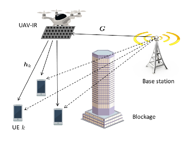
Consider a wireless BS serving a set of cellular user equipment (UE) over the downlink via mmWave frequencies. The BS has transmit antennas, and each downlink UE has a single antenna. As shown in Fig. 1, we assume that the direct transmission channel between the BS and each UE is blocked, and the received signal via the direct link is negligible. In order to bypass the obstacle and improve the received power at each UE, a UAV-IR with reflective elements is deployed to assist downlink transmissions towards NLOS UEs. By leveraging the mobility of the UAV, the UAV-IR can potentially replace each direct NLOS link with two connected LOS links, by adjusting its position and reflecting mmWave signals from the BS towards each UE. Since an IR is a passive device, it cannot acquire the channel state information (CSI) or process received signals. To enable information exchange, an active antenna is embedded onto the UAV to receive a control signal from the BS and feedback information from served UEs.
II-A Communications Capacity and Power Cost
Consider a multi-user multiple-input-single-output downlink communications, in which the BS serves downlink UEs via a common mmWave band. The BS-IR channel is denoted as , and the IR-UE link for each UE is given as . Let be the set of IR components. For each component , the phase shift is denoted by and the amplitude attenuation is . Consequently, the IR’s reflection coefficient is . In order to provide downlink communications to multiple UEs, the BS precodes the transmit signal as an vector , where is the precoding vector, and is the unit-power information symbol for UE . The received signal at UE will thus be: , where is the receiver noise at UE . In order to separate the mmWave propagation environment with the IR’s reflection, we rewrite the received signal at UE equivalently in the following form:
| (1) |
where is a vector of the UAV-IR reflection coefficients and is the CSI of the connected BS-IR-UE link towards UE without any phase shift. The channel measurement approach for IR-aided cellular communications has been investigated in [9]. Here, we assume that the CSI of each BS-IR-UE link only depends on the location of the UAV-IR, and the channel matrix is known to both BS and UAV-IR, as long as is given. Therefore, the signal-to-interference-and-noise-ratio (SINR) of downlink communications from the BS, reflected by the IR, to each UE is
| (2) |
where is a precoding matrix at the BS. Consequently, the total achievable rate that the IR-assisted communication can provide to all UEs is
| (3) |
where is the downlink bandwidth.
In order to maintain LOS links with both the BS and UEs, the UAV-IR needs to frequently adjust its location, based on the real-time CSI. Thus, the power cost of a UAV-IR includes the UAV’s hovering power , mobility power , and the adjustment power for the IR’s reflection coefficients. In order to facilitate beamforming transmissions at the BS and ensure a reliable reflection at the IR, we assume that downlink communication only happens when the UAV-IR has a fixed location. Let be the speed of the UAV-IR, and is an indicator function which equals to one when the UAV is in the hovering state with a zero speed. Therefore, the power cost of the UAV-IR for providing downlink reflection service is .
II-B Problem Formulation
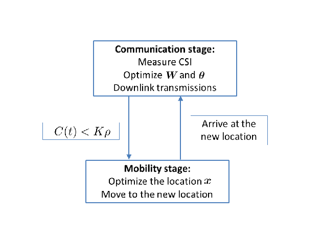
As shown in Fig. 2, in order to provide efficient and reliable mmWave communications to downlink UEs, a dynamic deployment for the UAV-IR is considered, where the deployment process is divided into two sequential and alternating stages: communication and movement. In the communication stage, the UAV-IR stays at a fixed location while reflecting mmWave signals towards downlink UEs. However, once the average downlink rate is lower than a threshold , blockage occurs in the downlink channels for most UEs. In this case, the current communication stage ends, and the UAV-IR moves to a new position, so as to establish LOS links for efficient downlink communications. Here, we assume that the CSI is constant within each coherence time slot . Given that the duration of a communication stage depends on the real-time CSI and the length of a movement stage is determined by the movement distance and the UAV’s speed, both stages can last for several coherence time slots.
Our goal is to jointly optimize the precoding matrix at the BS, the reflection coefficient of the IR, and the location of the UAV, such that, before the UAV’s onboard energy is exhausted, the total achievable data transmissions that the UAV-IR provides to downlink UEs can be maximized, i.e.:
| (4a) | ||||
| s. t. | (4b) | |||
| (4c) | ||||
| (4d) | ||||
where the random integer denotes the final time slot of the UAV’s service, is the average speed of the UAV during the coherence time , is the maximal transmit power at the BS, and is the initial onboard energy of the UAV. Therefore, the objective function (4a) is the summation of downlink data transmissions that the UAV-IR provides to all UEs before the end of its service, (4b) is the power limitation at the BS, (4c) is the reflection constraints at the IR, and (4d) is the energy constraint of the UAV.
The optimization problem in (4) is challenging to solve for two reasons. First, during each coherence time, the objective function (4a) is non-convex with respect to the optimal variables , and . Second, the relationship between the location of the UAV-IR with the CSI is not explicitly known. Meanwhile, it is impractical to apply a sweeping search by moving the UAV-IR to all possible locations and measuring the real-time CSI for each UE . In order to address these challenges, in Section III-A, the beamforming matrix and reflection coefficient will be optimized, given a fixed location and known CSI. Next, the location optimization of the UAV-IR will be addressed using a learning-based approach to model the mmWave communication environment.
III Optimal Deployment of UAV-IR
In this section, the precoding matrix at the BS, the reflection coefficients at the IR, and the location of the UAV-IR will be jointly optimized in a real-time manner to maximize the downlink transmission capacity. In particular, a distributional reinforcement learning (DRL) framework is proposed to model the downlink CSI during each communication stage, based on the UEs’ feedback.
III-A Optimal precoding and reflection coefficients
First, we focus on the communication stage, where the UAV-IR has a fixed location and the downlink CSI for each UE is known. Then, for each coherence time, (4) is reduced to optimize the precoding matrix and the reflection coefficients, so as to maximize the downlink sum-rate, i.e.:
| (5a) | ||||
| s. t. | (5b) | |||
| (5c) | ||||
To solve this non-convex problem, we apply the Lagrangian dual transform method [13], introduce an auxiliary variable , and equivalently rewrite the objective function (5a) into the following form:
| (6) |
By holding and fixed and setting , we have the optimal value of as . Then, for a fixed , the optimization problem of and is reduced to
| (7a) | ||||
| s. t. | (7b) | |||
where . Given that (7) is a multiple-ratio fractional programming problem, we can fix the value of and alternatively, and solve the optimization problem via an iterative approach, detailed as follows.
III-A1 Optimal precoding matrix
For a fixed , the optimal precoding problem becomes
| (8a) | ||||
| s. t. | (8b) | |||
The multiple-ratio fractional programming function in (8a) is equivalent to , where is an auxiliary vector [13, Theorem 2]. Since is a convex function with respect to both and , , an iterative approach can be applied to optimize and alternatively. First, we fix and set . Then, the optimal value of is
| (9) |
Then, by fixing , the optimal can be given by
| (10) |
where is the minimum value such that holds. By alternating between (9) and (10), the precoding matrix will eventually converge to the unique and optimal value , with a computational complexity of .
III-A2 Optimal reflection coefficients
Next, we fix the value of and optimize the reflection coefficient in (7), i.e.:
| (11a) | ||||
| s. t. | (11b) | |||
Similarly, an auxiliary vector is introduced, so that (11a) equivalently becomes , which is convex with respect to both and . Therefore, the unique and optimal value of the reflection coefficients can be obtained via a similar alternative approach as the precoding optimization. First, the optimal for a given is
| (12) |
Then, the optimization of the reflection coefficient for a fixed becomes
| (13a) | ||||
| s. t. | (13b) | |||
where , , and . Given that is a positive-definite matrix, is quadratic concave with respect to . Meanwhile, the constraint (13b) is a convex set. Thus, (13) is solvable using a Lagrange dual decomposition [8] with a computational complexity of .
Therefore, given the CSI of each BS-IR-UE link, the precoding matrix and reflection coefficient can be optimally and uniquely determined. Next, the optimal location of the UAV-IR will be studied to guarantee a LOS channel for each BS-IR-UE link.
III-B Optimal location of the UAV-IR
During the communication stage, at the end of each coherence time , the UAV-IR can get feedback from each UE about the downlink transmission performance. Whenever the average rate per UE is smaller than , i,e, , blockage occurs in the downlink channels for most UEs. In this case, the UAV-IR needs to move and rebuild LOS links. The optimization problem of the UAV-IR’s location is given as
| (14a) | ||||
| s. t. | (14b) | |||
To determine the optimal location for each communication stage, a DRL framework is designed to learn the dynamic communication environment and model the relationship between the UAV’s location and downlink CSI. In our DRL framework, the downlink CSI is the communication environment, the UAV-IR is the agent that takes action to change its location from to , and the communication state is a vector of the received signal power at each UE, where . At the end of each coherence time, the UAV-IR receives reward , which is the total received data in the downlink transmission. Due to the small‐scale fading of mmWave channels, the downlink CSI may vary between different time slots, even for a fixed location of the UAV-IR. Thus, it is more suitable to consider the reward as a random variable with respect to , rather than a determined value. Meanwhile, is the state transition probability from to after taking action .
To properly capture the relationship between the UAV’s movement and downlink transmission performance, first, a policy is introduced to define the probability that the UAV-IR will move by , under a current state . Meanwhile, to quantify the potential of each action for improving the downlink rate under a state , we define the return function of each state-action pair for any time slot as
| (15) |
where , and . Here, discounts the future rewards in the current estimation for each state-action pair. If , the return function will approximate (14a). Thus, the return function (15) defines a cumulative discounted reward that the UAV-IR can achieve by reflecting mmWave signals at location for the next communication stage. Meanwhile, given that is a random variable, it is necessary to model a distribution function of (15) to identify the return value for each state-action pair. Once the return distribution is known, the optimal policy that maximizes the expectation of the cumulative rewards can be defined by . Thus, the optimal location of the UAV-IR for the next time slot will be .
In order to model the return distribution for each state-action pair, a quantile regression (QR) method [12] is applied. A -quantile model approximates the target distribution , using a discrete function with variable locations of supports and fixed quantile of probabilities [9], for a fixed integer . Mathematically, a -quantile model is denoted by , with a cumulative probability for . The objective is to find the optimal location for each support, such that the “distance” between the target distribution and the -quantile model can be minimized. However, given that the actual return distribution is not explicitly known, an empirical distribution will be formed, based on the UEs’ feedback during each time slot, and is used as the target distribution to model the return approximation . To quantify the “distance” between two distribution functions, the quantile regression loss is defined as [12],
| (16) |
where , is the weight of regression loss penalty, and is the square of approximation error. Thus, the problem of the return distribution modeling becomes to minimize the quantile regression loss, i.e.,
| (17) |
Since the objective function in (17) is convex with respect to , the minimizer can be found by conventional gradient-descent approaches with a computational complexity of . As a result, for each state-action pair, its return distribution can be approximated by a Q-quantile via (17).
Consequently, in the location optimization problem of the UAV-IR, after observing a communication state , the UAV-IR can estimate the expected return value for each action , by computing the marginal distribution of , and choose the optimal location that maximize the summation of future downlink transmissions via
| (18) |
After the UAV-IR arrives at the new location and provides downlink service to UEs, a new state and reward will be updated at the end of the time slot. Given the downlink transmission, the empirical distribution can be updated via a Q-learning approach, where . As a result, the return distribution is updated by minimize the distance from the target distribution , based on (17). The training and update algorithm of the DRL model for the real-time optimal deployment of the UAV-IR is summarized in Algorithm 1. The convergence property of this iterative algorithm has been proved in [9, Theorem 1].


IV Simulation Results and Analysis
For our simulations, we consider a uniform square array of antennas at both the BS and the UAV-IR with and , and the number of downlink UEs is . The BS is located at , each UE’s location follows an i.i.d. two-dimensional Gaussian with zero height, and the mobility pattern of each UE follows a Markov decision process in [3]. A building located at with a height of meters permanently blocks direct BS-UE links. The path loss and mmWave channel model are based on [9]. For communication parameters, we set GHz, MHz, dBm, and second. The average speed of the UAV during the mobility stage is m/s, the maximal onboard energy is Wh, and the power cost are W, W, and W. In the DRL model, we set , and . In order to have a finite state-action space, we discretize the communication state to be a binary vector, where if the received power of UE is smaller than a threshold , ; otherwise . The discrete action space is defined as: is “ascend by one meter”, is “descend by one meter”, and to are “move towards UE by one meter” for each .
In Fig. 3(a), we first show the empirical probability of having a LOS downlink channel towards each UE. To evaluate the performance of the proposed DRL approach for the UAV-IR deployment, a direct transmission, a static IR, and a UAV-IR without learning are introduced as baselines. The static IR is placed at to bypass the building and establish LOS BS-IR-UE links. However, the bodies of human users may block mmWave channels. For the non-learning scheme, the UAV-IR moves towards a UE by one meter, every time downlink blockage occurs. As shown in Fig. 3(a), the static IR scheme yields a LOS probability of around . Due to the mobility of the UAV, the proposed UAV-IR scheme can maintain a LOS probability of over , and the non-learning UAV-IR results in a probability of over . Moreover, as the altitude of the UAV-IR increases, the LOS downlink probability will naturally increase for both UAV-IR schemes. However, since the DRL-based deployment can estimate the potential of each action in improving the mmWave communication over a long term, the proposed method always yields a higher LOS probability than the non-learning scheme.
Fig. 3(b) shows the time-average data rate of mmWave downlink communications, as the transmit power of the BS increases. When the transmit power increases from to dBm, the downlink data rates of all schemes become higher. First, compared with the direct transmission scheme, the proposed UAV-IR approach yields a performance gain of over two-folds in the downlink data rate, due to a higher LOS probability. Meanwhile, the DRL-enabled deployment of the UAV-IR improves the communication performance by over and , compared to the non-learning UAV-IR and the static IR, respectively. For the non-learning scheme, its short-sighted strategy causes a frequent movement of the UAV-IR, thus yielding a lower downlink rate.
Fig. 3(c) shows how to choose the optimal action under a worst-case state , where the received power at each UE is lower than the threshold. In this case, Fig. 3(c) shows the return distribution and the expected return value of each action. Since yields the highest expected reward, the optimal action under the worst-case communication state is to increase the altitude of the UAV-IR by one meter.
V Conclusion
In this paper, we have proposed a novel DRL-enabled approach to the deploy a UAV-IR for efficient downlink transmissions over mmWave frequencies towards multiple UEs. To maximize the downlink sum-rate, the optimal precoding matrix at the BS and reflection coefficient of the IR have been derived. In order to model the propagation environment of mmWave communications, the DRL method has been proposed to optimize the location of the UAV-IR, so as to maximize the downlink communication capacity. Simulation results show that the proposed DRL-based deployment of the UAV-IR yields a significant advantage, compared to a non-learning UAV-IR, a static IR, and a direct transmission schemes, in terms of the average data rate and the achievable downlink LOS probability. Future research will focus on multiple UAV-IRs in outdoor communication scenarios with mobile users.
References
- [1] W. Saad, M. Bennis, and M. Chen, “A vision of 6G wireless systems: Applications, trends, technologies, and open research problems,” IEEE Network, vol. 34, no. 3, pp. 134 – 142, May/June 2020.
- [2] O. Semiari, W. Saad, and M. Bennis, “Joint millimeter wave and microwave resources allocation in cellular networks with dual-mode base stations,” IEEE Transactions on Wireless Communications, vol. 16, no. 7, pp. 4802–4816, May 2017.
- [3] Q. Zhang, W. Saad, and M. Bennis, “Reflections in the sky: Millimeter wave communication with UAV-carried intelligent reflectors,” in Proc. of IEEE Global Communications Conference, Hawaii, USA, Dec 2019, pp. 1–6.
- [4] M. N. Soorki, W. Saad, and M. Bennis, “Ultra-reliable millimeter-wave communications using an artificial intelligence-powered reflector,” in Proc. of IEEE Global Communications Conference, Hawaii, USA, Dec 2019, pp. 1–6.
- [5] P. Wang, J. Fang, X. Yuan, Z. Chen, H. Duan, and H. Li, “Intelligent reflecting surface-assisted millimeter wave communications: Joint active and passive precoding design,” arXiv preprint arXiv:1908.10734, 2019.
- [6] D. Yue, H. H. Nguyen, and Y. Sun, “Analysis of intelligent reflecting surface-assisted mmWave doubly massive-MIMO communications,” arXiv preprint arXiv:2003.00282, 2020.
- [7] Y. Cao and T. Lv, “Intelligent reflecting surface aided multi-user millimeter-wave communications for coverage enhancement,” arXiv preprint arXiv:1910.02398, 2019.
- [8] H. Guo, Y.-C. Liang, J. Chen, and E. G. Larsson, “Weighted sum-rate maximization for reconfigurable intelligent surface aided wireless networks,” IEEE Transactions on Wireless Communications, vol. 19, no. 5, pp. 3064–3076, Feb 2020.
- [9] Q. Zhang, W. Saad, and M. Bennis, “Millimeter wave communications with an intelligent reflector: Performance optimization and distributional reinforcement learning,” arXiv preprint arXiv:2002.10572, 2020.
- [10] A. Taha, M. Alrabeiah, and A. Alkhateeb, “Deep learning for large intelligent surfaces in millimeter wave and massive MIMO systems,” in Proc. of IEEE Global Communications Conference, Hawaii, USA, Dec 2019, pp. 1–6.
- [11] C. Huang, R. Mo, C. Yuen et al., “Reconfigurable intelligent surface assisted multiuser MISO systems exploiting deep reinforcement learning,” arXiv preprint arXiv:2002.10072, 2020.
- [12] W. Dabney, M. Rowland, M. G. Bellemare, and R. Munos, “Distributional reinforcement learning with quantile regression,” in Proc. of Thirty-Second AAAI Conference on Artificial Intelligence, New Orleans, Louisiana, USA, Feb 2018.
- [13] K. Shen and W. Yu, “Fractional programming for communication systems—part I: Power control and beamforming,” IEEE Transactions on Signal Processing, vol. 66, no. 10, pp. 2616–2630, Mar 2018.