Phase slips driven by acoustic waves in Bose-Einstein condensates with ring topology
Abstract
Rotational superradiance is one of the most fascinating phenomena in black-hole physics. Here, with the aim of probing quantum properties of superradiance in the lab, we investigate the interaction of the acoustic waves with quantum vortices in Bose-Einstein condensates (BEC) in the framework of dissipative mean-field model. We find the conditions of the acoustic-induced quantum phase slips in condensates with ring topology and discuss the possibility of observing an acoustic analogue of quantum superradiance in ultracold atomic gases.
I Introduction
Rotation of any macroscopic body with internal degrees of freedom could amplify incident radiation. It is a generic process with energy transfer from one medium to another. Superradiance is a process of the amplification of some modes of a scattering wave (amplitude increase with constant frequency) after the scattering on a rotating object. Such a phenomenon exists in different variations in quantum mechanics, astrophysics and relativityBekenstein and Schiffer 1998.
In relativity, superradiance is intimately connected to tidal acceleration. As superradiance is related to rotation energy transmission, it does not necessarily have to be only relativistic phenomenon and is predicted in Newtonian dynamics as well Brito et al. 2015; Cardoso 2013. Rotational superradiance in curved spacetime has been described by Yakov Zel’dovich Zel’dovich 1971; Zel’dovich 1972. Quantization of this process makes rotating objects spontaneously radiating. A very similar mechanism is the cause of the black hole evaporation, even in the absence of rotation Unruh 1981; Hawking 1974.
Superradiance has been predicted theoretically and observed experimentally in many classical and quantum physical systems Brito et al. 2015; Torres et al. 2017; Faccio and Wright 2019; Faccio and Wright 2019; Demirkaya et al. 2019; Demirkaya et al. 2020; Marino et al. 2009. As known, circulations in superfluids are quantized, and amplification cannot happen without decay of persistent current (reducing of topological charge) Federici et al. 2006. Phase slips in toroidal condensates Wright et al. 2013; Yakimenko et al. 2015; Ramanathan et al. 2011 are accompanied by vortex transfer to the condensate periphery. There vortex decays and the rotational energy of the superflow converts into acoustic waves. Thus, acoustically driven phase slips can be treated as quantum analogue of rotational superradiance. Acoustic wave dynamics and interaction with a vortex are quite similar in the classic Ford and Smith 1999; Howe 2003 and quantum Tsubota et al. 2013; Meppelink et al. 2009; Ville et al. 2018; Ghazanfari and Mustecaplioglu 2014 systems. However, it is worth to mention that for the strong perturbations shock waves appear instead of acoustic waves Wang et al. 2015. Acoustic wave interaction with vortex in BEC is dramatically affected by quantization of angular momentum. Here we address the following question: how does quantum nature of the vortices in BEC influence the superradiance?
A very recent experiment Torres et al. 2017 in the water tank demonstrated the amplification of surface waves after scattering on draining vortex. Amplification also depends on the angular velocity of the vortex Basak and Majumdar 2003a; Basak and Majumdar 2003b. In homogeneous infinite condensate quantum superradiance is forbidden Anacleto et al. 2011. Furthermore, in the fluid, the drain is not always required for a vortex for superradiant sound scattering; this effect may occur even when the fluid density drops to zero at the vortex core Slatyer and Savage 2005.

Here we investigate a quantum analogue of the experiment Torres et al. 2017 and suggest a setup for observation of quantum superradiance in ultracold atomic gases. We study the interaction of acoustic waves with a vortex trapped in a toroidal trap and quasi-2D and 3D geometry with a mini-trap on the main axis for holding vortex thread.
Our paper is organized as follows. In Sec. II, we define the model we use to investigate the system. In Sec. III we investigate dissipative Bose-Einstein condensate in a toroidal trap with additional external oscillating potential and with an imprinted vortex in purpose to explore the superradiance effect and its quantized properties. In Sec. IV, neglecting the noise, we investigate the influence of the dissipation parameter on damping decrement for acoustic waves extending along the 2D and 3D elongated condensates. On the main axis of the oblong condensate, with a Gauss-like potential, we create a trap smaller than a transverse width of the condensate with the imprinted vortex in it. We study a parametric area of acoustic wave’s amplitude and frequency for observing vortex emission from the trap. We summarize our results in the concluding Sec. V.
II Model
In the mean-field approximation, the dynamics of a system of weakly interacting degenerate atoms at finite temperature is describing by the dissipating Gross-Pitaevskii equation (dGPE):
| (1) | ||||
Here is a complex wave function of the condensate, is a chemical potential of the condensate, is a phenomenological dissipation parameter and for physical systems , for more complex models parameter connected to the temperature of the condensate via fluctuation-dissipation theorem, is the coupling strength, m is the mass of the atom, nm is the s-wave scattering length, is reduced Planck constant. is an external potential contains of two parts: static harmonic trap and dynamic perturbation .
To find initial stationary ground state we solve Eq. (1) without perturbing potential () start with a random complex wave function and use imaginary time propagation method. The essence of the method lies in the fact that evolution occurs in complex time (Wick rotation at the angle ). Imaginary time propagation essentially implements the steepest descent method in the energy space Bao et al. 2006.
To find the numerical solution of the deterministic GPE (1) we use the split-step Fourier transform method Agrawal 2013; Bao and Cai 2012. In all our simulations, the initial states have persistent current (single-charged vortex thread). To get this state, we imprint vortex into stationary solution without rotation using the following ansatz:
| (2) |
where is a normalization constant introduced to preserve the number of atoms, is the topological charge of the imprinted vortex line ( for a single charged vortex and for a single charged anti-vortex respectively), coordinates of the imprinted vortex in polar coordinate system, and is the healing length in the point of highest density of the condensate. We assume that the vortex line is parallel to the -axis.
To improve the vortex form, we apply the imaginary time propagation method with a little number of iterations to all states with imprinted vortices, taking into account that the ITP decreases the state energy Bao et al. 2006. We have found that the coordinates of the vortex cores do not change significantly during the short imaginary time evolution, while the density shape near the vortices changes considerably Snizhko et al. 2016.

III Wave propagation in toroidal 3D condensate


We consider toroidal BEC of atoms in the harmonic trap with frequencies Hz, and peak-density ring radius m; two-particle interaction parameter , and dissipation parameter . We use these physical parameters because they are related to the experiment with the same geometry (see Ref. Wright et al. 2013).
Dissipative system is non-conservative; therefore, chemical potential is adjusted after each step to conserve number of particles . The external potential consists of static harmonic trap and periodic quantum-mechanical ”piston” perturbation See Fig. 1 (a). Trapping potential is harmonic on and directions:
| (3) |
The perturbation potential is periodic in time (turns off after the moment ) wide elliptical Gauss-like beam (See Fig. 1 (b)) which main axis is tangent to the outer ring of the torus:
| (4) |
where is the amplitude of the perturbation, , is estimated outer Thomas-Fermi radius of the tor, parameters and make perturbation thin in x-direction and wide in y-direction,
| (5) |
In our simulations we use physically small parameter that provides relaxation of the system but does not remove short-wavelength excitation as can be seen in Fig. 4 (a). Value of dissipation parameter does not significantly effect the edge of phase-slip, as it can be seen in Fig. 2 where map of after-evolution angular momentum per atom is shown in the same system with the same perturbation both with different dissipation parameter and . It mostly effects short-wavelength excitation and time of system’s relaxation after turning off the ”piston”.
We have made numerous simulations for multi-charged systems. Such systems may be unstable and decay with time Yakimenko et al. 2015. Presence of static repulsive potential destroys the axial symmetry and creates a weak-link in the energy barrier that separates states with different topological charge decreasing stability level comparing to the ’perfect’ ring. In a static system with perturbing potential locked at its highest amplitude, the last stable rotating state has topological charge 7. Oscillations lead to decay of persistent current as in the case of single-charged systems, but its behavior is more spontaneous and unpredictable.
Three frequencies characterize our system: the rotational quantum, the critical frequency for inner and outer surface modes excitation, and the angular frequency of sound propagating around the ring. The rotational quantum is defined via parameters of the system: Hz. The critical frequency can be obtained from the analysis of small azimuthal perturbations around the stationary state Dubessy et al. 2012, and it gives (in dimensionless units) Hz, where is a radial width of the ring in dimensionless units. For over-critical frequencies we observe massive vortex nucleation (see Fig. 4 (a)). The speed of sound in a uniform superfluid fluid at is , where is a peak density. From here we obtain the angular frequency of sound propagating around the ring Hz. Our model works well until the frequency of perturbation is noticeably below the angular frequency of sound; however, when the frequency exceeds it, we have shock waves and vortex turbulence.
The phase-slip edge has clear peak around critical frequency - narrow frequency domain in approximately 5 Hz where persistent current decay under the influence of perturbations with smaller amplitudes (see Fig.2 (b)). In Fig. 3 shown phase-slip edge for two different larger ring with smaller critical frequency. atoms in the harmonic trap with frequencies Hz, and peak-density ring radius m; two-particle interaction parameter , and dissipation parameter , critical frequency estimation that comes from surface model Hz. In both cases there is a noticeable or at least slightly noticeable peak near the critical frequency.
Our simulations uncovered some problems in this configuration. The main problems are wave reflection and interference. The time of reaction on perturbation is quite long (a few seconds). The size of the inner circle is big enough to contain many surface modes, and it is the cause of nucleation of a huge number of vortices and antivortices at over-critical frequencies of the perturbing potential. In general, the results are not sufficient enough, they only provide us the edge of persistent current stability area but the final state of evolution beyond it is unpredictable.
To minimize all these factors, we consider a system with the same topology but in geometry more similar to the experiment Torres et al. 2017. More on this in the next section.
IV Wave propagation in elongated 2D/3D condensate


In this section we study analogy of water tank: we have elongated along the -axis tiny two-dimensional condensate and pinned in the mini-trap on the -axis vortex thread (See Fig. 1 (c)). Here we can avoid a limitation of the annulus and neglect the interference. In case when the transverse frequency of harmonic trap is high compared to the radial ones the condensate has a plane-shaped form and can be described by quasi-two-dimensional (2D) wave function . We assume that the elongated system is tightly confined in a direction. Therefore, the transverse motion of condensate is frozen, and the wave function in Eq. 1 can be separated into two parts:
| (6) |
where is the ground state wave function in the oscillatory potential Here is an oscillatory length in the direction.
In order to ignore interference effects, we first need to configure the system the way not to let reflected waves interact with a vortex thread. For this purpose we consider two-dimensional elongated along the -axis BEC of atoms trapped in harmonic potential in a transverse direction with Hz and in a box-like potential in a longitudinal direction:
| (7) | ||||

where is the length of the condensate on x direction is comparable with a size of the chamber from the previous section m, and is the depth of the box-like potential on x-direction. As a source of acoustic waves we use periodic in time Gauss-like perturbation localized around the left edge of the box-like potential:
| (8) |
where is the amplitude of the perturbation, is coordinate of the center of the potential, - the width of the potential, and - frequency of the perturbation. Due to the dissipation, acoustic waves are damping with distance as . To find the relation between the dissipation parameter and logarithmic decrement , we numerically solve the Eq. 1 for single-period excitation. Also, dissipation causes a loss of particles during evolution, so the chemical potential is adjusted at each time step such that the number of condensed particles remains . For a set of different we save coordinate of density maximum each moment assuming that is the center of the acoustic wave. From these data, we can calculate decrement and build of relation in Fig. 5 as black solid circles.
Keeping the length of the condensate constant, we choose the dissipation parameter . For studying acoustic wave - vortex interaction, it is necessary to pin the vortex thread; otherwise, it will not remain in an unstable region of peak density. Therefore, to the trapping potential, we add additional Gauss-like mini-trap potential for keeping imprinted vortices inside of it:
| (9) |
where is a depth of the mini-trap (), is the distance from the edge of the condensate to the center of the mini-trap, is a radius of the mini-trap for imprinted vortex. The size of the trap is very small m in diameter. The main benefit of such a small size is that the only one surface mode can be excited instead of the torus case when the inner ring surface is a massive vortex factory.
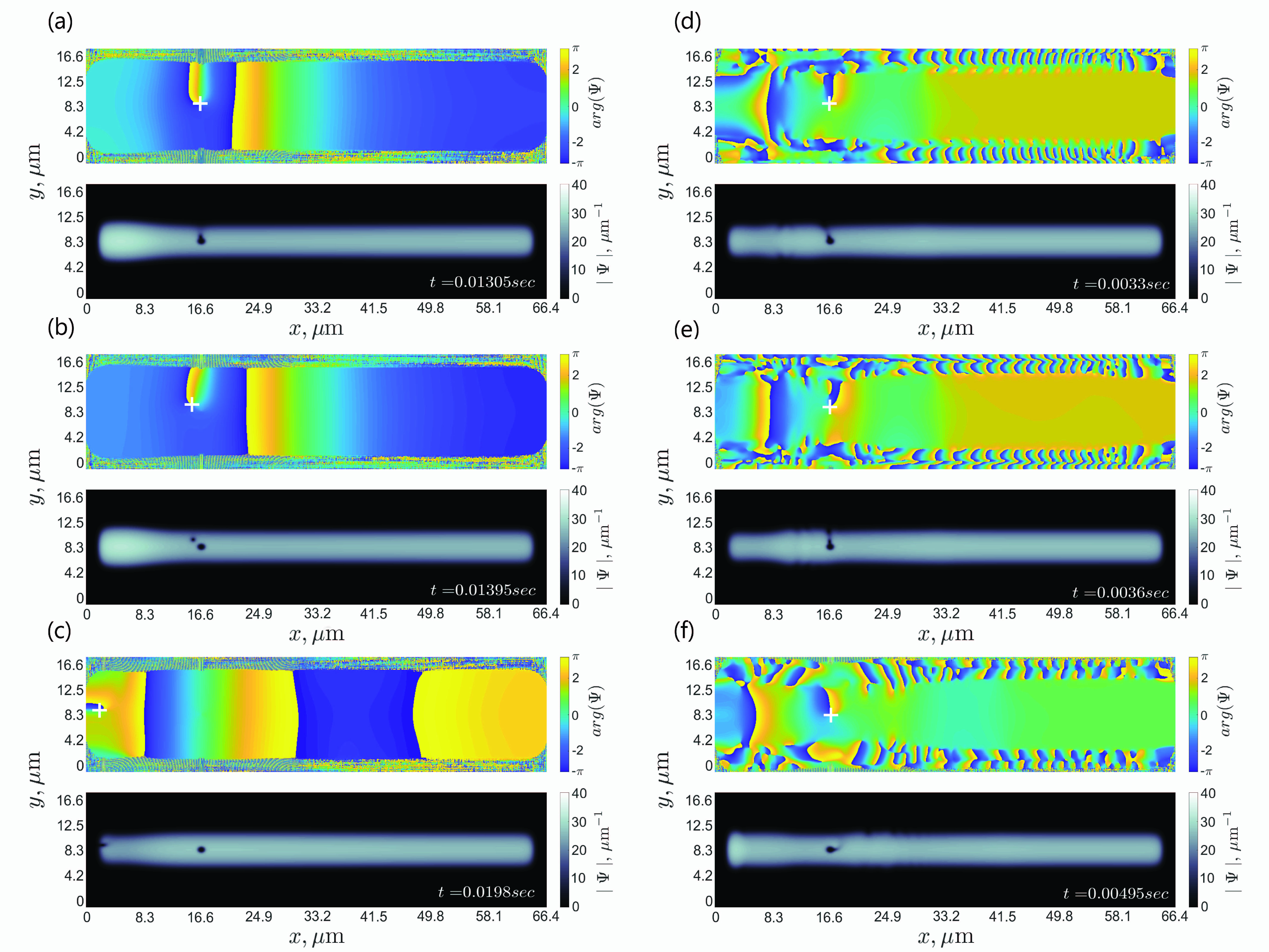
In this configuration, acoustic wave - vortex interaction happens much faster and more clear. It always takes a few dozens of s, and the final state is well-defined. If there is enough energy for exciting inner circle surface mode and emit the vortex, it happens when the first front of the acoustic wave reaches the vortex thread. After leaving the mini-trap, vortex moves to the left(right) edge of the condensate (to the source of perturbation), and when it gets to the low-density area, converts into outer surface mode (see Fig. 7 (a-c)).
Unlike the previous section where we were calculating angular momentum per atom for finding the edge of persistent current stability, here we detect vortex cores in a small area with a center in the mini trap. The edge of vortex emission from mini-trap is shown in Fig. 6.
The area of amplitude and frequency of the perturbation, which can cause vortex emission, is bounded both by the top and bottom perturbation frequency, as is shown in Fig. 6. For frequencies above the top edge of phase slips the excess energy goes to the creation of a dipole, which almost instantly annihilates with the emission of a sound wave, which can be seen in Fig. 7 (f); therefore, this secondary acoustic wave may amplify some modes of initial acoustic wave.
Same has been done in elongated 3D system when z-direction is not frozen (in harmonic trap on and directions and in box-like on direction). Area of perturbation parameters that lead to vortex emission is shown in Fig. 8. In low frequency/amplitude regime system demonstrates good match with 2D case. More cylinder-like high-density system for high frequencies and amplitudes demonstrates shock wave behavior and vortex turbulence similar to Mossman et al. 2018.
V Conclusions
We have investigated persistent current decay driven by acoustic waves in trapped ultracold gases with ring topology. The phase slips are studied in 3D toroidal trap, quasi-2D and 3D elongated condensate with vortex lines pinned in a density dips. In all considered cases, acoustic waves were created by the amplitude-modulated repulsive beam.
Firstly, in the 3D case, it has been found out that the phase-slips can be induced by the acoustic perturbations; however, the wave reflection and interference influence the system essentially. Therefore, even though there is a visible edge of persistent current stability, well above this threshold the final states of the condensate become practically unpredictable. In toroidal geometry, the system reacts slowly to excitation and due to the presence of many vortices dynamics are complicated. Dissipation eliminates small-scaled noise, but it cannot solve the problem of interfering with a reflected wave: weak dissipation does not remove even short-wavelength excitations, strong dissipation quenches the wave´s amplitude on scales much smaller than the size of the inner ring and, therefore, cannot lead to decay of persistent current.
On the other hand, the elongated quasi-2D system shows the reliable edge of the phase-slip area in space of acoustic wave parameters (frequency and amplitude). An interesting feature has been observed: the area of phase-slip existence is bounded by the top and bottom wave frequency for the same wave amplitude and this effect might find an application in atomtronics for developing residual-current devices in BEC by analogy with electrical devices but for frequency instead of voltage. It is worth mentioning that the system remains stable for high out-of-edge frequencies. When side perturbation switches to turbulent regime, it excites outer-surface modes and vortex turbulence. The imprinted vortex thread interacts with them creating dipoles that immediately annihilate with sound emission (that might amplify initial wave) but itself remains locked in mini-trap. The vortex thread can also be emitted with turning into outer surface mode later. Unlike the classic water tank experiment Torres et al. 2017 a quantum vortex in BEC has a small energy. Thus, it may require the use multicharged persistent currents for experimental observation of amplification of acoustic waves in ultracold atomic gases. We hope the results described here can provide a further research direction for studies of quantum properties of rotational superradiance in BEC.
References
- Bekenstein and Schiffer (1998) J. D. Bekenstein and M. Schiffer, Physical Review D 58 (1998), 10.1103/physrevd.58.064014.
- Brito et al. (2015) R. Brito, V. Cardoso, and P. Pani, Superradiance Lecture Notes in Physics , 35–95 (2015).
- Cardoso (2013) V. Cardoso, General Relativity and Gravitation 45, 2079–2097 (2013).
- Zel’dovich (1971) Y. B. Zel’dovich, JETP Lett. 14 , 180 (1971).
- Zel’dovich (1972) Y. B. Zel’dovich, Sov. Phys. - JETP, Vol. 35, No. 6 , 1085 (1972).
- Unruh (1981) W. G. Unruh, Physical Review Letters 46, 1351–1353 (1981).
- Hawking (1974) S. W. Hawking, Nature 248, 30–31 (1974).
- Torres et al. (2017) T. Torres, S. Patrick, A. Coutant, M. Richartz, E. W. Tedford, and S. Weinfurtner, Nature Physics 13, 833 (2017).
- Faccio and Wright (2019) D. Faccio and E. Wright, Physical Review Letters 123 (2019), 10.1103/physrevlett.123.044301.
- Demirkaya et al. (2019) B. Demirkaya, T. Dereli, and K. Guven, “Analog black holes and energy extraction by super-radiance from bose einstein condensates (bec) with constant density,” (2019).
- Demirkaya et al. (2020) B. Demirkaya, T. Dereli, and K. Guven, Physica Scripta 95, 055001 (2020).
- Marino et al. (2009) F. Marino, M. Ciszak, and A. Ortolan, Physical Review A 80 (2009), 10.1103/physreva.80.065802.
- Federici et al. (2006) F. Federici, C. Cherubini, S. Succi, and M. P. Tosi, Physical Review A 73 (2006), 10.1103/physreva.73.033604.
- Wright et al. (2013) K. C. Wright, R. B. Blakestad, C. J. Lobb, W. D. Phillips, and G. K. Campbell, Physical Review Letters 110, 025302 (2013), arXiv:1208.3608 [cond-mat.quant-gas] .
- Yakimenko et al. (2015) A. I. Yakimenko, Y. M. Bidasyuk, M. Weyrauch, Y. I. Kuriatnikov, and S. I. Vilchinskii, Physical Review A 91 (2015).
- Ramanathan et al. (2011) A. Ramanathan, K. C. Wright, S. R. Muniz, M. Zelan, W. T. Hill, C. J. Lobb, K. Helmerson, W. D. Phillips, and G. K. Campbell, Physical Review Letters 106 (2011), 10.1103/physrevlett.106.130401.
- Ford and Smith (1999) R. Ford and S. G. L. Smith, Journal of Fluid Mechanics 386, 305–328 (1999).
- Howe (2003) M. S. Howe, “Theory of vortex sound,” (2003).
- Tsubota et al. (2013) M. Tsubota, M. Kobayashi, and H. Takeuchi, Physics Reports 522, 191–238 (2013).
- Meppelink et al. (2009) R. Meppelink, S. B. Koller, and P. V. D. Straten, Physical Review A 80 (2009), 10.1103/physreva.80.043605.
- Ville et al. (2018) J. Ville, R. Saint-Jalm, î L. Cerf, M. Aidelsburger, S. Nascimbene, J. Dalibard, and J. Beugnon, Physical Review Letters 121 (2018), 10.1103/physrevlett.121.145301.
- Ghazanfari and Mustecaplioglu (2014) N. Ghazanfari and î E. Mustecaplioglu, Physical Review A 89 (2014), 10.1103/physreva.89.043619.
- Wang et al. (2015) Y.-H. Wang, A. Kumar, F. Jendrzejewski, R. M. Wilson, M. Edwards, S. Eckel, G. K. Campbell, and C. W. Clark, New Journal of Physics 17, 125012 (2015).
- Basak and Majumdar (2003a) S. Basak and P. Majumdar, Classical and Quantum Gravity 20, 3907–3913 (2003a).
- Basak and Majumdar (2003b) S. Basak and P. Majumdar, Classical and Quantum Gravity 20, 2929–2936 (2003b).
- Anacleto et al. (2011) M. Anacleto, F. Brito, and E. Passos, Physics Letters B 703, 609–613 (2011).
- Slatyer and Savage (2005) T. R. Slatyer and C. M. Savage, Classical and Quantum Gravity 22, 3833–3839 (2005).
- Bao et al. (2006) W. Bao, I.-L. Chern, and F. Y. Lim, Journal of Computational Physics 219, 836 (2006).
- Agrawal (2013) G. P. Agrawal, Nonlinear fiber optics (Elsevier Science, 2013).
- Bao and Cai (2012) W. Bao and Y. Cai, arXiv e-prints , arXiv:1212.5341 (2012), arXiv:1212.5341 [cond-mat.quant-gas] .
- Bao et al. (2006) W. Bao, I.-L. Chern, and F. Y. Lim, Journal of Computational Physics 219, 836 (2006).
- Snizhko et al. (2016) K. Snizhko, K. Isaieva, Y. Kuriatnikov, Y. Bidasyuk, S. Vilchinskii, and A. Yakimenko, Phys. Rev. A 94, 063642 (2016), arXiv:1610.08837 [cond-mat.quant-gas] .
- Dubessy et al. (2012) R. Dubessy, T. Liennard, P. Pedri, and H. Perrin, Physical Review A 86 (2012), 10.1103/physreva.86.011602.
- Mossman et al. (2018) M. E. Mossman, M. A. Hoefer, K. Julien, P. G. Kevrekidis, and P. Engels, Nature Communications 9 (2018), 10.1038/s41467-018-07147-4.