DFT-spread-OFDM Based Chirp Transmission
Abstract
In this study, we propose a framework for chirp-based communications by exploiting DFT-s-OFDM (DFT-s-OFDM). We show that a well-designed FDSS (FDSS) filter for DFT-s-OFDM can convert its single-carrier nature to a linear combination of chirps circularly translated in the time domain. Also, by exploiting the properties of the Fourier series and Bessel function of the first kind, we analytically obtain the FDSS filter for an arbitrary chirp. We theoretically show that the chirps with low ripples in the frequency domain result in a lower BER (BER) via less noise enhancement. We also address the noise enhancement by exploiting the repetitions in the frequency. The proposed framework offers a new way to efficiently synthesize chirps that can be used in IoT (IoT), DFRC (DFRC) or wireless sensing applications with existing DFT-s-OFDM transceivers.
Index Terms:
Chirps, DFT-s-OFDM, DFRC, FDSS.I Introduction
Chirps are prominent for radar and communication applications in the sense that they can sweep a large bandwidth while still being constant-envelope signals, i.e., they provide robustness against non-linear distortions. Recently, there is a growing interest in their potential use in today’s major communication systems, e.g., 3GPP 5G (5G) NR (NR), LTE (LTE), and IEEE 802.11 Wi-Fi, to address some emerging applications such as short-range wireless sensing, DFRC, and IoT. However, the physical layers of these communication systems are based on OFDM (OFDM). In this study, we aim at addressing the challenge of synthesizing chirps within an OFDM framework.
There is an extensive literature dealing with chirps for communications. To provide a longer range and higher resolution for radar systems, chirps were first utilized by S. Darlington at Bell Labs [3]. They also introduce the idea of encoding bits as negative or positive slopes in TF (TF) plane. In [4], an orthogonal amplitude-variant linear chirp set where each chirp has a different chirp rate is investigated. In [5], X. Ouyang and J. Zhao presented a way of constructing orthogonal chirps by introducing a term to the exponent of DFT (DFT) kernels. As the proposed method in [5] translates the chirps in the frequency domain, the signal bandwidth increases with the number of chirps. To limit the bandwidth, they proposed additional up-sampling and filtering operations, which folds the chirps in the frequency domain. The Fresnel transform and FrFT (FrFT) were adopted to generate orthogonal chirp sets in [5] and [6], respectively. In [7], an iterative receiver is proposed to decrease the BER under frequency-selective channels for chirps. In addition, a proprietary CSS (CSS) modulation, called LoRa (LoRa), was introduced by Samtec for IoT applications. The chirps for wireless sensing were also brought up in IEEE 802.11 Wi-Fi meetings, e.g., [8]. To the best of our knowledge, there is no study that investigates CSCs for chirp-based communications and reveals its relation to OFDM.
In this paper, we present a method that generates modulated CSCs based on DFT-s-OFDM adopted in 3GPP 5G NR and 3GPP LTE. The contributions of this study based on this method can be listed as follows:
A flexible framework for chirps: The proposed framework relies on the design of FDSS filter applied after DFT spreading to convert the Dirichlet sinc functions [9] to a set of chirps translated uniformly in time. Since the introduced method controls the frequency domain behavior of the chirps over the OFDM subcarriers, it allows utilization of techniques developed for OFDM for chirp-based communications.
Theoretical FDSS design: By exploiting the properties of the Bessel functions of the first kind, we show that the FDSS filter for arbitrary chirps can be designed analytically based on the convolutions of up-sampled sequences relying on the Bessel function of the first kind. We also discuss the closed-form expressions for linear and sinusoidal chirps.
Transceiver compatibility: The proposed framework shows that existing DFT-s-OFDM transceivers can modulate and demodulate the CSCs, which enlarges the applications of existing DFT-s-OFDM transceivers. We also investigate the noise enhancement problem and its mitigation.
Precise bandwidth control: Since CSCs are generated in the frequency domain through an FDSS filter, the proposed method achieves precise control of the chirp bandwidth without additional filtering operations mentioned in [5].
II Circularly-Shifted Chirps with DFT-s-OFDM
Consider a communication scheme where the data symbols are transmitted over the basis functions constructed by translating a chirp signal circularly in time, where is the amount of circular shift. We assume that the shifts in time are uniformly spaced between 0 and , i.e., , where is the chirp duration. The complex baseband signal can then be expressed as
| (1) |
where is the th data symbol (e.g., QPSK (QPSK) symbols) and is the phase of the carrier for the th basis function. Therefore, the instantaneous frequency of the th chirp signal around the carrier frequency can be obtained as Hz. The waveform given in (1) is a linear combination of the basis functions related to chirps. However, it is implicitly related to DFT-s-OFDM. This relation can be shown as follows:
Let be an arbitrary band-limited function with the period of . Hence, it can be expressed as
| (2) |
where is the th Fourier coefficient given by
| (3) |
By using (2) and , (1) can be expressed as
| (4) |
where and are integer values. The approximation is due to the fact that is a band-limited function, i.e., is a decaying Hermitian symmetric function as goes to positive or negative infinity. Finally, by sampling with the period , the discrete-time signal can be obtained as
| (5) |
Hence, as shown in Figure 1, (1) is a special DFT-s-OFDM symbol that can be implemented by 1) calculating the -point DFT of a data vector, i.e., , 2) multiplying each element of the output of DFT with the corresponding Fourier coefficient, i.e., FDSS or windowing in frequency, and 3) calculating the -point IDFT (IDFT) of the shaped sequence after padding it with zero symbols (e.g., guard subcarriers in OFDM).
In this study, without loss of generality, we assume and to ensure that the FDSS occurs within the bandwidth spanned by subcarriers. Therefore, the chirp bandwidth should be less than or equal to . Let Hz be the maximum frequency deviation of each basis function, where is a positive real number. Hence, the effective bandwidth of the transmitted signal is Hz. Therefore, must hold true to form the CSCs via (5).
Note that FDSS was discussed in 3GPP LTE and 3GPP 5G NR uplink as an implementation-specific option to reduce PAPR (PAPR) further for DFT-s-OFDM. Based on (5), we show the same DFT-s-OFDM transmitter can also generate CSCs by choosing the shaping coefficients properly without compromising the other features of the physical layer design in these communication systems. As compared to the method in [5], it also does not cause any bandwidth expansion as the chirps are circularly-shifted versions of each other in the time domain, which eliminates additional processing to avoid aliases discussed in [5].

II-A Receiver
As shown in Figure 1, a typical DFT-s-OFDM receiver can demodulate the received CSCs. After the CP (CP) is discarded, the DFT of the received signal is calculated. In the frequency domain, the impact of the channel is removed with a single-tap MMSE (MMSE) FDE (FDE)11 1 Single-tap MMSE-FDE and linear MMSE estimator based on matrix notations of the corresponding operations are identical.. The modulation symbols are obtained after an -IDFT operation on the equalized signal vector. For a practical receiver, the shaping coefficients can be considered as part of the channel frequency response and estimated through channel estimation procedure. From this aspect, the proposed scheme does not require any change from a practical DFT-s-OFDM receiver. On the other hand, if the shaping coefficients are available at the receiver a priori, the receiver can perform better as they do not need to be estimated.
It is worth noting that FDSS coefficients for chirps are often not unimodular, i.e., for all and . Therefore, a single-tap FDE causes noise enhancement for the subcarriers where . Also, ISI (ISI) occurs after the IDFT de-spreading operation since MMSE is a biased estimator. By utilizing the error rate analysis given for plain DFT-s-OFDM [10], the overall impact of MMSE-FDE on the data symbols can be calculated by obtaining the SNR (SNR) after the equalization as
| (6) |
where . The equation (6) shows that and the equality holds for for all . Under the assumption of the ISI being Gaussian, the error rate for CSCs with arbitrary modulation can be calculated by using . As demonstrated in Section IV through theoretical results based on (6), this assumption is fairly accurate.
II-A1 Reducing Noise Enhancement
The noise enhancement due to the FDSS can be substantially reduced by achieving a frequency diversity without distorting transmitting CSCs as follows: Assume that only every other bins of the input of -point DFT are utilized for data symbols. It can be shown that the resulting vector after the -point DFT consists of repetitions of the -point DFT of the data symbols. Since each repetition is multiplied with different FDSS coefficients, it enables utilization of frequency diversity techniques without changing the original signal bandwidth. At the receiver side, repetitions can be combined as for , where is the symbol on the th subcarrier. After equalizing with MMSE-FDE, by considering the scaled noise, can be calculated as , where . Since is a summation based on , the amplitude variation of is less than the original case. Hence, the noise enhancement is substantially mitigated at the expense of SE (SE) as shown in Section IV.
II-B Compatibility with Other Features of Physical Layer
Equation (1) provides insight into how existing techniques in OFDM-based systems can be utilized for chirps.
II-B1 Multiple access
To support users in the uplink within the same band without distorting the chirps, one simple approach is to up-sample the shaped sequence by a factor of in the frequency domain. Since the up-sampling in the frequency domain causes repetition in the time [11], the transmitted signal consists of repetitions of CSCs within . The zeroes due to the up-sampling in the frequency domain can be utilized by the other users, e.g., each user maps the up-sampled shaped sequence to a distinct set of subcarriers by shifting the sequence. If the channel is assumed to be flat (e.g., a strong line-of-sight path exists), the zeroes bins mentioned in Section II-A1 can be also be utilized for multiple access.
II-B2 Multiple antennas
Equation (1) shows that if a MIMO (MIMO) precoder is applied per subcarrier or a subcarrier group, it can distort the chirps. Hence, a MIMO precoder can be applied based on the bandwidth of the chirp to avoid distortion. The diversity combining techniques, such as maximum-ratio combining, can also be trivially employed since the received signal is processed in the frequency domain.
II-B3 Channel estimation
Since the proposed framework utilizes CP, it allows the receiver to estimate the channel in the frequency domain. In one approach, a single data symbol can be activated, e.g., and . In this case, the elements of the shaped sequence can be utilized as pilots in the frequency domain. In another approach, the shaped sequence is upsampled and every other subcarrier is utilized for a pilot symbol as in a typical OFDM transmission.
II-B4 DFRC
Achieving communications and radar functionality with the same waveform can address the under-utilized radar spectrum [12]. The proposed framework enables that the correlation properties of the chirps can be exploited while allowing them to carry information. For example, if only a portion of data symbols are activated with an index modulation [13], a large amount of information can be transmitted while utilizing the correlation properties of the chirps for range and velocity estimation.
III Analytical FDSS Filter Design
In general, it is not trivial to obtain the FDSS coefficients analytically for an arbitrary chirp. In this section, we first discuss the chirps where the corresponding FDSS coefficients can be expressed in closed-form. We then derive a theoretical framework for FDSS coefficients to synthesize chirp with an arbitrary trajectory in time and frequency plane.
III-A FDSS Filters in Closed-Form for Special Chirps
III-A1 Sinusoidal Chirps
Let the instantaneous frequency of around the carrier frequency be a sinusoidal function given by Therefore, . It is well-known that can be decomposed as [14]
| (7) |
where is the Bessel function of the first kind of order . Hence, is equal to for sinusoidal chirps.
III-A2 Linear Chirps
Assume that the instantaneous frequency of around the carrier frequency changes form Hz to Hz, i.e., which results in . The shaping coefficients can be obtained as , where and are the Fresnel integrals with cosine and sine functions, respectively, and and [15].
III-B FDSS Filters in Analytic-Form for Arbitrary Chirps
Let be a periodic function with the period of , where . For , changes between and Hz. By using the Fourier series of , we can express as
| (8) |
Let and be the th Fourier coefficients of and , respectively. By using (7), and can be obtained as
| (9) |
and
| (10) |
respectively, where is Kronecker delta function. Since (8) is a multiplication of and for , the Fourier series of can be calculated via the convolution theorem as
| (11) |
Note that (11) requires the calculation of infinitely many convolutions of infinite-length sequences. Although this is not tractable in general, for practical chirps, it can be accurately calculated since 1) Fourier series quickly converge (i.e., limited ) for chirps used in practice, e.g., triangular chirps, 2) Due to the properties of the Bessel function of the first kind, the limits of and are zeros as approaches to infinity, and 3) FDSS filter design is often an offline procedure.
III-B1 Triangular Chirp
Triangular chirp allows a radar system to estimate not only the range but also the target’s velocity [16]. The corresponding FDSS filter for triangular chirp can be obtained by using (11), analytically. Assume that the down-chirp first is transmitted in the first half of the symbol with a following up-chirp. The corresponding within one period can be expressed as
| (12) |
The Fourier series coefficients of can then be obtained as and
| (13) |
If the up-chirp is transmitted on the first half with a following down-chirp, and the corresponding is equal to the negative of (13). Since for both cases, the FDSS coefficients can be obtained analytically as .
IV Numerical Results
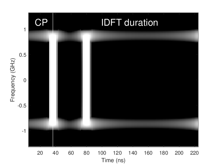
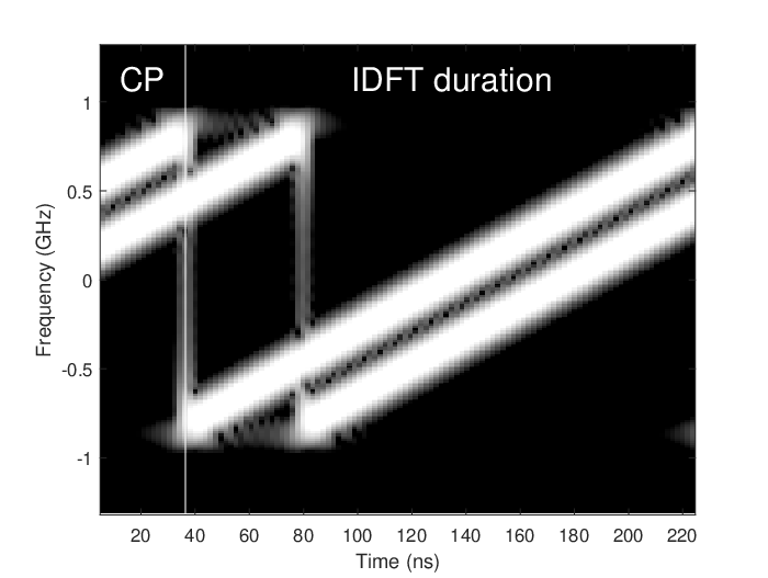

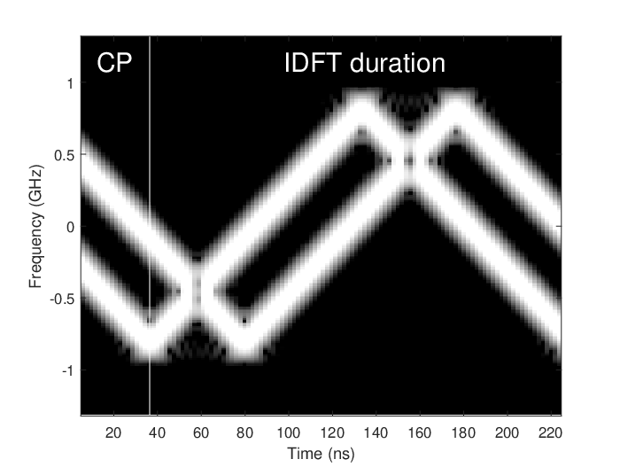
For simulations, we consider IEEE 802.11ay OFDM PHY, where the symbol duration and the CP duration are ns and ns, respectively. We assume that the transmitter uses subcarriers. For chirps, we choose to not distort chirps due to the truncation. We generate the data symbols based on QPSK and use CSCs unless otherwise stated. We consider a multipath channel where the power delay profile is dB. While the first path follows Rician distribution with a -factor of 10, the other two paths are based on Rayleigh distributions. For the channel coding, IEEE 802.11ay LDPC (LDPC) code with the rate of is employed, where the codeword length is . We consider linear, sinusoidal, and triangular CSCs. As a reference, we also provide the results for plain DFT-s-OFDM (i.e., no FDSS). For triangular chirp, we obtain the FDSS filter based on (11). We assume that FDSS filter is known at the receiver.
In Figure 2, we demonstrate that a DFT-s-OFDM transmitter is capable of synthesizing CSCs with arbitrary trajectories in time and frequency. For this analysis, we assume and the rest is set to 0. Since a plain DFT-s-OFDM signal is a form of single carrier waveform, the symbols and appear as two pulses in time as in Figure 2. In contrast, the same symbols result in two linear, sinusoidal, and triangular CSCs transmitted in simultaneously as in Figure 2-2, respectively. We observe that there is a sudden frequency change for linear chirps. This is due to the fact that sinusoidal chirp is a continuous periodic function while a linear chirp is a discontinuous periodic function in (2). This abrupt change in the frequency can also be observed as a distortion that affects the constant-envelope nature of the linear chirp in the time. Theoretically, such distortion is inevitable for with finite support. However, it can be mitigated by decreasing the maximum frequency deviation or allowing a tolerable amount of leakage beyond the channel bandwidth by choosing and in (5). The abrupt instantaneous frequency changes are avoided for the sinusoidal and triangular chirps. Figure 2 also demonstrates that the triangular chirps can be synthesized accurately with (11).

In Figure 3, the power spectral density and the FDSS coefficients of the aforementioned signals are compared. The main lobe of the spectrum is not flat for chirps. Particularly, a majority of the symbol energy is carried over the edge subcarriers for sinusoidal chirps. This is due to the fact that FDSS for chirps does not distribute symbol energy to the subcarriers evenly. While the amplitude variations for linear chirps are relatively mild, they can be large for sinusoidal and triangular chirps. As discussed in Section II-A, large ripples degrade the BER performance due to the noise enhancement with MMSE-FDE. Particularly, the magnitude of the shaping coefficients can be very small for sinusoidal and triangular chirps (see the fluctuations in Figure 3). Therefore, the subcarriers with small magnitude shaping coefficients are more prone to noise.


In Figure 4 and Figure 5, BER and BLER (BLER) curves are provided. For both , the simulation results match well with the theoretical BER curves based on (6). For and uncoded bits, a large degradation occurs for the sinusoidal and triangular chirps in AWGN (AWGN) while it is approximately 1 dB for linear chirps, as compared to plain DFT-s-OFDM. The main reason for this degradation is non-unimodular FDSS coefficients. When LDPC is introduced, for both AWGN and fading channels, the degradation is approximately 0.5 dB for linear chirps while it is around 3 dB for the sinusoidal and triangular chirps. For , the error rate substantially reduces for chirps as the receiver combines the signal in the frequency as discussed in Section II-A1 and mitigate the noise enhancement. While the performance difference between DFT-s-OFDM and linear chirps is negligible in this scenario, the gap reduces to 0.8 dB for sinusoidal and triangular chirps.
V Concluding Remarks
In this study, we show that modulated CSCs can be generated with DFT-s-OFDM via a well-designed FDSS filter. For obtaining FDSS filter analytically for an arbitrary chirp, we also develop a theoretical framework based on the Bessel function of the first kind and the Fourier series of the trajectory in time and frequency. We show that a typical DFT-s-OFDM receiver with a single-tap FDE-MMSE can decode the modulated chirps. We theoretically quantify the impact of the magnitude variations in the shaping coefficients on SNR after the equalization and discuss how to mitigate noise enhancement through repetitions in the frequency. As the corresponding FDSS for linear chirps has fewer magnitude variations as compared to the sinusoidal and triangular chirps, linear CSCs performs similar to the plain DFT-s-OFDM.
The main benefit of the proposed approach is that it provides insight into how chirps can be synthesized and used for communications without introducing major modifications to the physical layer of today’s wireless standards. Since the techniques developed for OFDM can be utilized through the introduced framework, it paves the wave for developing new methods for DFRC and IoT applications.
References
- [1] S. Hoque, C.-Y. Chen, and A. Şahin, “A wideband index modulation with circularly-shifted chirps,” in Proc. IEEE Consumer Commun. & Netw. Conf. (CCNC), Jan. 2021, pp. 1–6.
- [2] S. Hoque and A. Şahin, “Index-modulated circularly-shifted chirps for dual-function radar & communication systems,” in Proc. IEEE Global Communications Conference - ISAC Workshop, Dec. 2020, pp. 1–6.
- [3] S. Darlington, “Pulse transmission,” Patent US2 678 997A, Dec., 1949.
- [4] H. Shen and A. P. Suppappola, “Diversity and channel estimation using time-varying signals and time-frequency techniques,” IEEE Trans. Signal Process., vol. 54, no. 9, pp. 3400–3413, Sep. 2006.
- [5] X. Ouyang and J. Zhao, “Orthogonal chirp division multiplexing,” IEEE Trans. Commun., vol. 64, no. 9, pp. 3946–3957, Sep. 2016.
- [6] Y. Ju and B. Barkat, “A new efficient chirp modulation technique for multi-user access communications systems,” in Proc. IEEE International Conference on Acoustics, Speech, and Signal Processing (ICASSP), vol. 4, May 2004, pp. iv–937.
- [7] R. Bomfin, M. Chafii, and G. Fettweis, “Low-complexity iterative receiver for orthogonal chirp division multiplexing,” in Proc. IEEE Wireless Communications and Networking Conference Workshop (WCNCW), Apr. 2019, pp. 1–6.
- [8] T. X. Han and et. al., “Wi-Fi sensing – follow up,” IEEE 802.11-19/1500, Sep. 2019.
- [9] A. Şahin, R. Yang, E. Bala, M. C. Beluri, and R. L. Olesen, “Flexible DFT-S-OFDM: Solutions and challenges,” IEEE Commun. Mag., vol. 54, no. 11, pp. 106–112, Nov. 2016.
- [10] M. D. Nisar, H. Nottensteiner, and T. Hindelang, “On performance limits of DFT Spread OFDM systems,” in Proc. IEEE Mobile and Wireless Communications Summit, Jul. 2007, pp. 1–4.
- [11] T. Frank, A. Klein, and T. Haustein, “A survey on the envelope fluctuations of DFT Precoded OFDMA signals,” in Proc. IEEE International Conference on Communications (ICC), May 2008, pp. 3495–3500.
- [12] B. Paul, A. R. Chiriyath, and D. W. Bliss, “Survey of RF communications and sensing convergence research,” IEEE Access, vol. 5, pp. 252–270, 2017.
- [13] E. Başar, Ü. Aygölü, E. Panayırcı, and H. V. Poor, “Orthogonal frequency division multiplexing with index modulation,” IEEE Trans. Signal Process., vol. 61, no. 22, pp. 5536–5549, Aug. 2013.
- [14] J. Proakis and M. Salehi, Fundamentals of Communication Systems. Pearson Education, 2013.
- [15] C. Cook and M. Bernfeld, Radar Signals: An Introduction to Theory and Application. Artech House, 1993.
- [16] S. Saponara, M. S. Greco, and F. Gini, “Radar-on-chip/in-package in autonomous driving vehicles and intelligent transport systems: Opportunities and challenges,” IEEE Signal Process. Mag., vol. 36, no. 5, pp. 71–84, 2019.