Three-Dimensional Invisibility to Superscattering Induced by Zeeman-Split Modes
Abstract
We report that the fundamental three-dimensional (3-D) scattering single-channel limit can be overcome in magneto-optical assisted systems by inducing nondegenerate magnetoplasmonic modes. In addition, we propose a 3-D active (magnetically assisted) forward-superscattering to invisibility switch, functioning at the same operational wavelength. Our structure is composed of a high-index dielectric core coated by indium antimonide (InSb), a semiconductor whose permittivity tensorial elements may be actively manipulated by an external magnetic bias . In the absence of , InSb exhibits isotropic epsilon-near-zero (ENZ) and plasmonic behavior above and below its plasma frequency, respectively, a frequency band which can be utilized for attaining invisibility using cloaks with permittivity less than that of free space. With realistic magnitudes as high as T, the gyroelectric properties of InSb enable the lift of mode degeneracy, and the induction of a Zeeman-split type dipolar magnetoplasmonic mode that beats the fundamental single-channel limit. This all-in-one design allows for the implementation of functional and highly tunable optical devices.
Dynamically manipulating the scattering characteristics of resonant structures comprises a valuable platform for the development of functional, tunable optical devices enabling a variety of applications Kuznetsov et al. 2016; Tsakmakidis et al. 2017a, including optical sorting Shilkin et al. 2017, visible-to-invisible switching Rybin et al. 2017, cloaking-to-superscattering switching Huang et al. 2018, directionality inversion Arruda et al. 2016; Liu et al. 2018; Zouros et al. 2020, all-optical switching Shcherbakov et al. 2015, multipolar interference Limonov et al. 2017, quantum emitters Cihan et al. 2018, or light-matter interaction enhancement at the subwavelength regime via superscattering operation Qian et al. 2019. A pathway to actively manipulating the scattering response is through external-agent based alteration of the material properties of the structure, which retains the geometry and operational wavelength fixed. Techniques to achieve this dynamic switching between different states include the electrically configurable liquid crystal based meta-optic devices which change the phase or the orientation of the surrounding liquid crystal Komar et al. 2017, the use of phase-change materials that allow for a permittivity change by transiting between amorphous and crystalline states using external laser beams Lepeshov et al. 2019, magneto-optical media whose permittivity can be modified by an external magnetic bias Kort-Kamp et al. 2013, ferromagnetic materials whose permeability can be manipulated via temperature variations Arruda et al. 2015, or ultrafast nonlinear optical switching based on light-induced change of a material’s dielectric permittivity (normally, to low values) Caspani et al. 2016.
In this work, we demonstrate that in optimized 3-D core-shell spherical particles consisting of a high-index dielectric core and an InSb semiconductor coating, we can overcome the fundamental single-channel limit of the scattering efficiency Tribelsky and Luk’yanchuk 2006, by appropriately inducing a magnetoplasmonic resonance. In addition, while keeping the geometry and operational wavelength fixed, we can transform the configuration to an invisible state simply by switching off the external magnetic field , utilizing the dynamic properties of the structure’s active semiconductor coating, InSb, whose permittivity can be manipulated by relatively small or modest values of . In the presence of low magnitudes, the coating exhibits gyroelectric along with plasmonic activity, resulting in the induction of magnetoplasmonic modes Chen et al. 2015; Chochol et al. 2017 which—different from recent two-dimensional (2-D) superscattering schemes Qian et al. 2019—are here nondegenerate, i.e., of Zeeman-split type Almpanis 2018; Almpanis et al. 2020; Zouros et al. 2020. We show that these nondegenerate magnetoplasmonic resonances exhibit strong directional scattering. In the absence of , and for the same operational wavelength, InSb exhibits isotropic ENZ and plasmonic behavior above and below its plasma frequency, respectively, a frequency band that can be utilized for attaining invisibility Alù and Engheta 2005; Tsakmakidis et al. 2019. This off-to-on transition from invisibility to superscattering operation is robust under material losses and gives rise to a huge enhancement in the scattering efficiency. The findings obtained from our formal analytical solution are in excellent agreement with full-wave simulations (COMSOL), thereby establishing the validity of the proposed set-up.
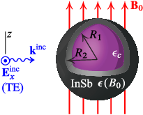
In Fig. 1 we show the configuration of the forward-superscattering to invisibility magnetic switch. The main structure consists of a -radius high permittivity dielectric core—with being the free space permittivity—coated by a -radius shell consisting of semiconductor InSb. The whole configuration is exposed in external magnetic field . Since is -oriented, InSb’s permittivity tensor is expressed in cartesian coordinates by —where denotes transposition—with , and Tsakmakidis et al. 2017b. In the aforementioned relations we have used realistic material parameters where accounts for interband transitions, rad/s is the plasma angular frequency (with the electron density, the elementary charge and electron’s effective mass, where is electron’s rest mass), is cyclotron angular frequency, and the damping angular frequency which accounts for losses. In case of null , InSb turns isotropic with and . In addition, the core-shell structure is nonmagnetic and it is located in free space. The set-up is illuminated by a normal to impinging transverse electric (TE) plane wave—i.e., the incident electric field is normal to the plane of incidence, therefore, if the plane of incidence is the -plane as shown in Fig. 1, then is -polarized. To examine the electromagnetic (EM) response of the magnetic switch proposed in this work, the solution of EM plane wave scattering by dielectric-gyroelectric core-shell spheres is necessary. This is feasible by the discrete eigenfunction method employed in Li and Ong 2011; Kolezas et al. 2019 for homogeneous spheres and spheroids. In the Supplemental Material sup we extend that method and we rigorously develop a full-wave analytical solution of EM scattering by dielectric-gyroelectric spheres. The scattering efficiency is given by
| (1) |
where is the free space wavelength, , the expansion coefficients of the scattered electric field (sup, Eq. (S2)), and , the spherical harmonics and angular momentum indices, respectively. In the long wavelength limit, the spectrum is dominated by the electric dipolar (ED) and magnetic dipolar (MD) responses for which . In particular, for purely isotropic scatterers, the ED response to the scattering efficiency is obtained when only the expansion coefficient contributes in Eq. (1), while the MD response stems exclusively from .
When the MD response is negligible and the ED response dominates the spectrum, transparency can be achieved by utilizing an isotropic lossless ENZ coating with permittivity and a radii ratio determined by Alù and Engheta 2005
| (2) |
By appropriately selecting , , Eq. (2) yields the radii ratio for which cancellation of the ED term to the spectrum is achieved. Eq. (2) is ideally suited for lossless and non-dispersive materials. To make a rough estimation of a possible transparency window, using Eq. (2), we neglect losses by setting zero damping term in Drude-Lorentz model of InSb, we set as an average value of in the range from THz to THz, and along with , Eq. (2) yields . This radii ratio can serve as a tentative basis also in our case, where the InSb coating is lossy and dispersive.
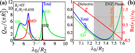
At first, we examine the optical response of the lossy and dispersive core-shell particle in the absence of , where InSb is isotropic. By employing the radii ratio , we obtain the spectrum shown in Fig. 2(a). In blue line we show the total normalized which involves all terms of Eq. (1), up to an index for which convergence is ensured. In addition, we also depict the separate MD/ED and electric quadrupolar (EQ) terms. The latter one contributes to Eq. (1) by employing only the expansion coefficient. The ED/MD resonances appearing in the range from up to in Fig. 2(a), are typical subwavelength resonances due to the high-index dielectric core. On the contrary, the EQ/ED peaks above are plasmonic resonances of the coating. This is because at frequencies below the plasma frequency , InSb changes its properties from ENZ to plasmonic. This is illustrated in Fig. 2(b) which focuses in the transition region indicated by the gray circle in Fig. 2(a). There, the two domains (ENZ/plasmonic) are marked by dark-gray and bright-gray colors, the boundary of which is determined by the plasma frequency at (or THz). The real part of the coating permittivity depends almost linearly on the wavelength, as shown in Fig. 2(b). In particular, at (which corresponds to frequency equal to ), while at ( THz). In brief, Fig. 2(b) indicates that inside the ENZ region of the coating, the normalized from solely the ED contribution (which is similar to the total normalized ) is suppressed, resulting in a respective transparency window. However, as we shall see below, this is not the case when .
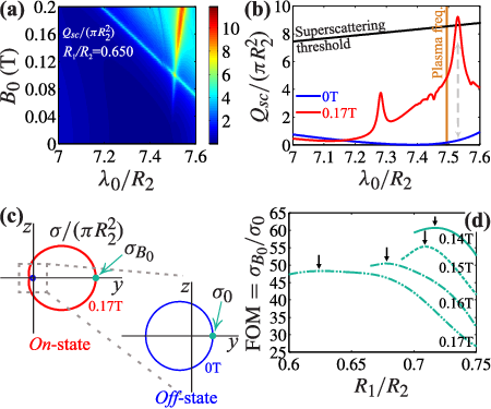
In Fig. 3(a) we show the map of the normalized , versus the external magnitude, in the same wavelength window as the one in Fig. 2(b). All the other parameters of the configuration are the same with the ones used in Fig. 2. The deep blue region at T in Fig. 3(a) corresponds to the transparency window discussed in Fig. 2(b), where normalized is almost zero. By switching on the external magnetic field, and varying its magnitude, we can monitor the impact that it has on this transparency window. In particular, for T, sharp peaks in intense red color appear, which correspond to high values. In Fig. 3(b) we plot the normalized for two particular choices of , i.e., and T. The first case () is already discussed but shown for comparison. At T, two dominant scattering modes appear, where the longer-wavelength one has greater normalized than the dipole-superscattering single-channel threshold given by Tribelsky and Luk’yanchuk 2006
| (3) |
The corresponding dipole-superscattering threshold is shown in Fig. 3(b) in black. As shown, the superscattering resonance at can be dramatically suppressed by switching off the external magnetic field, where the particle becomes almost transparent. This transition from superscattering operation— ( T) to almost transparency— ( T), controlled entirely by the external magnetic bias, is pointed out with a dashed arrow in Fig. 3(b). In Fig. 3(c) we depict the radiation pattern of the structure when the latter operates exactly at , by plotting the normalized bistatic scattering cross section on -plane by varying , for the two different values that allow for the on-off switching. When T, the coated particle operates at a forward-superscattering state with , i.e., the value of in the forward direction. Contrariwise, when T, the particle is at off-state/transparency with the respective point in the suppressed radiation pattern being . We point out here that the lower-wavelength and smaller in amplitude resonance in Fig. 3(b) at , when T, is much below the single-channel limit. Additionally, this mode does not exhibit unidirectional scattering. In particular, this resonance shows a poor while, at the same instance, it has non negligible backscattering response rendering it improper for the application studied here.
Next, we define a figure of merit (FOM) as the ratio
| (4) |
For the specific example of Fig. 3(c), FOM is not optimized, and yields . In Fig. 3(d) we show that for a given there exists an optimal ratio for which FOM is maximized, yet the superscattering state is maintained. This is regarded as a 2-D optimization of FOM vs and . Fig. 3(d) shows four constant- curves of FOM vs for T, T, T and T. All values in Fig. 3(d) correspond to greater normalized than the fundamental single-channel limit. For the preceding example of T, optimal FOM is achieved at . The other maximum values shown by the arrows in Fig. 3(d) correspond to ( T), ( T) and to ( T).

In Fig. 4 we demonstrate the realization of the invisibility to superscattering magnetic switch for the optimized structure () at T. Fig. 4(a) depicts the total normalized for the on-state operation, along with its dipolar components. Higher-order terms—such as quadrupolar—are negligible in this regime. We note in passing that, for an isotropic spherical particle, the -mode index in Eq. (1) is degenerate, which means that a multipolar mode of electric or magnetic type is only characterized by the angular momentum index . However, this is not the case for gyroelectric spherical particles, as in the present case, where the lifting of the -degeneracy leads to separate Zeeman-split modes Almpanis 2018; Almpanis et al. 2020. Since in the regime of Fig. 4(a) only the dipolar () modes exist, we expect three () nondegenerate modes for each dipolar (parent) mode, with indices . However, the coupling of each one of such modes with the external radiation strongly depends on the angle of incidence and polarization Varytis and Stefanou 2016; Almpanis 2018. Our full-wave analytical calculations reveal that, in the specific spectral window of Fig. 4(a), for light impinging as shown in Fig. 1, we have while the nonzero expansion coefficients are only and and yield nondegenerate MD and ED modes, respectively. The contribution of and to the normalized is depicted in Fig. 4(a) by the red and green curves, respectively. As evident, the high peak at beats the superscattering limit. The physical mechanism behind this scattering maximization is attributed to the overlapping—as shown by the dashed gray line—of the nondegenerate MD and ED contributions, and is understood as a magnetoplasmon polariton excited in the magnetized InSb coating Brionand et al. 1972; Xia et al. 2019. Obviously, this is not the case when InSb is not magnetized, as in the case of Fig. 2(a) where the coating exhibits purely plasmonic properties and the specrtum is dominated by degenerate ED/EQ resonaces only. We note in passing that, the plasmonic Fano feature Luk’yanchuk et al. 2010 at —as shown in Fig. 4(a)—is attributed to the nondegenerate ED contribution, where a similar asymmetric feature has been also observed in ring-type cavities Hao et al. 2008. The respective spectrum at off-state is shown in Fig. 4(b), using the same scale as the one in Fig. 4(a). At , the system is almost transparent with normalized being significantly suppressed at . With a when T, this off-to-on transition results to a enhancement in . Fig. 4(c) depicts the radiation pattern when the system operates at . The forward-superscattering operation is achieved with a and an almost null radiation pattern when T. To validate our findings, we fully compare our analytical solution with COMSOL’s finite-element solver. The total normalized , as obtained by our method, is in full agreement with COMSOL, with the latter being depicted by the blue dots in Figs 4(a)–(c). To have a degree of comparison, our method yields and at the magnetoplasmonic resonance and at the transparency state, respectively, when . COMSOL’s respective values are and while the superscattering threshold is . In addition, the radiation pattern depicted in Fig. 4(c) is in full agreement with COMSOL. Fig. 4(d) depicts the on -plane for on- and off-state activity. Fig. 4(d)/right confirms the invisibility state since the incoming wave passes through the scatterer almost unperturbed, while the snapshot in Fig. 4(d)/left clearly illustrates the forward-scattering propagation along the positive -axis.
In conclusion, based on a rigorous analytical solution of the 3-D EM scattering problem by dielectric-gyroelectric spheres, corroborated by full-wave simulations, we introduced a high-permittivity/semiconductor structure for breaking the fundamental single-channel limit of the scattering efficiency. This operation is established by inducing nondegenerate dipolar magnetoplasmonic modes, in the subwavelength regime, by operating the structure below the semiconductor’s plasma frequency, and by applying a low external magnetic bias in the range T– T. Likewise, for the same operational wavelength and core-shell radii, for which superscattering operation occurs, we have also shown how 3-D invisibility can be attained, simply by turning off the external magnetic field. The latter effect stems from the dynamic properties of the coating, which change to a plasmonic behaviour in the absence of magnetic field, enabling a plasmonic based cloak. By a 2-D optimization relative to the external magnetic field and the radii ratio, we identified optimal states for which the on-off ratio of the forward scattering cross sections is maximized, with a concurrent enormous enhancement in the total scattering efficiency. Our findings could pave the way towards the design of highly functional and tunable optical devices, including state-of-the-art optical metasurfaces Neshev and Aharonovich 2018.
G.P.Z., E.A., and K.L.T. were supported by the General Secretariat for Research and Technology (GSRT) and the Hellenic Foundation for Research and Innovation (HFRI) under Grant No. 1819.
References
- Kuznetsov et al. (2016) A. I. Kuznetsov, A. E. Miroshnichenko, M. L. Brongersma, Y. S. Kivshar, and B. Luk’yanchuk, Science 354, aag2472 (2016).
- Tsakmakidis et al. (2017a) K. L. Tsakmakidis, O. Hess, R. W. Boyd, and X. Zhang, Science 358, eaan5196 (2017a).
- Shilkin et al. (2017) D. A. Shilkin, E. V. Lyubin, M. R. Shcherbakov, M. Lapine, and A. A. Fedyanin, ACS Photonics 4, 2312 (2017).
- Rybin et al. (2017) M. V. Rybin, K. B. Samusev, P. V. Kapitanova, D. S. Filonov, P. A. Belov, Y. S. Kivshar, and M. F. Limonov, Phys. Rev. B 95, 165119 (2017).
- Huang et al. (2018) Y. Huang, Y. Shen, C. Min, and G. Veronis, Opt. Mat. Expr. 8, 1672 (2018).
- Arruda et al. (2016) T. J. Arruda, A. S. Martinez, and F. A. Pinheiro, Phys. Rev. A 94, 033825 (2016).
- Liu et al. (2018) M. Q. Liu, C. Y. Zhao, and B. X. Wang, Nanoscale 10, 18282 (2018).
- Zouros et al. (2020) G. P. Zouros, G. D. Kolezas, E. Almpanis, K. Baskourelos, T. Stefański, and K. L. Tsakmakidis, Nanophotonics (2020), accepted for publication. DOI: 10.1515/nanoph-2020-0223.
- Shcherbakov et al. (2015) M. R. Shcherbakov, P. P. Vabishchevich, A. S. Shorokhov, K. E. Chong, D.-Y. Choi, I. Staude, A. E. Miroshnichenko, D. N. Neshev, A. A. Fedyanin, and Y. S. Kivshar, Nano Lett. 15, 6985 (2015).
- Limonov et al. (2017) M. F. Limonov, M. V. Rybin, A. N. Poddubny, and Y. S. Kivshar, Nature Photon. 11, 543 (2017).
- Cihan et al. (2018) A. F. Cihan, A. G. Curto, S. Raza, P. G. Kik, and M. L. Brongersma, Nature Photon. 12, 284 (2018).
- Qian et al. (2019) C. Qian, X. Lin, Y. Yang, X. Xiong, H. Wang, E. Li, I. Kaminer, B. Zhang, and H. Chen, Phys. Rev. Lett. 122, 063901 (2019).
- Komar et al. (2017) A. Komar, Z. Fang, J. Bohn, J. Sautter, M. Decker, A. Miroshnichenko, T. Pertsch, I. Brener, Y. S. Kivshar, I. Staude, and D. N. Neshev, Appl. Phys. Lett. 110, 071109 (2017).
- Lepeshov et al. (2019) S. Lepeshov, A. Krasnok, and A. Alù, ACS Photonics 6, 2126 (2019).
- Kort-Kamp et al. (2013) W. J. M. Kort-Kamp, F. S. S. Rosa, F. A. Pinheiro, and C. Farina, Phys. Rev. Lett. 111, 215504 (2013).
- Arruda et al. (2015) T. J. Arruda, A. S. Martinez, and F. A. Pinheiro, Phys. Rev. A 92, 023835 (2015).
- Caspani et al. (2016) L. Caspani, R. P. M. Kaipurath, M. Clerici, M. Ferrera, T. Roger, J. Kim, N. Kinsey, M. Pietrzyk, A. D. Falco, V. M. Shalaev, A. Boltasseva, and D. Faccio, Phys. Rev. Lett. 116, 233901 (2016).
- Tribelsky and Luk’yanchuk (2006) M. I. Tribelsky and B. S. Luk’yanchuk, Phys. Rev. Lett. 97, 263902 (2006).
- Chen et al. (2015) S. Chen, F. Fan, X. He, M. Chen, and S. Chang, Applied optics 54, 9177 (2015).
- Chochol et al. (2017) J. Chochol, K. Postava, M. Čada, and J. Pištora, Scientific Reports 7, 1 (2017).
- Almpanis (2018) E. Almpanis, Phys. Rev. B 97, 184406 (2018).
- Almpanis et al. (2020) E. Almpanis, G. P. Zouros, P. A. Pantazopoulos, K. L. Tsakmakidis, N. Papanikolaou, and N. Stefanou, Phys. Rev. B 101, 054412 (2020).
- Alù and Engheta (2005) A. Alù and N. Engheta, Phys. Rev. E 72, 016623 (2005).
- Tsakmakidis et al. (2019) K. L. Tsakmakidis, O. Reshef, E. Almpanis, G. P. Zouros, E. Mohammadi, D. Saadat, F. Sohrabi, N. Fahimi-Kashani, D. Etezad, R. W. Boyd, and H. Altug, Nat. Commun. 10, 4859 (2019).
- Tsakmakidis et al. (2017b) K. L. Tsakmakidis, L. Shen, S. A. Schulz, X. Zheng, J. Upham, X. Deng, H. Altug, A. F. Vakakis, and R. W. Boyd, Science 356, 1260 (2017b).
- Li and Ong (2011) J. L.-W. Li and W.-L. Ong, IEEE Trans. Antennas Propag. 59, 3370 (2011).
- Kolezas et al. (2019) G. D. Kolezas, G. P. Zouros, and K. L. Tsakmakidis, IEEE J. Sel. Top. Quantum Electron. 25, 4700912 (May/June 2019).
- (28) See Supplemental Material for details on the development of the rigorous analytical solution.
- Varytis and Stefanou (2016) P. Varytis and N. Stefanou, J. Opt. Soc. Am. B 33, 1286 (2016).
- Brionand et al. (1972) J. J. Brionand, R. F. Wallis, A. Hartstein, and E. Burstein, Phys. Rev. Lett. 28, 1455 (1972).
- Xia et al. (2019) L. Xia, X. Zhang, D. Wang, W. Zhang, and J. Han, Opt. Commun. 446, 84 (2019).
- Luk’yanchuk et al. (2010) B. Luk’yanchuk, N. I. Zheludev, S. A. Maier, N. J. Halas, P. Nordlander, H. Giessen, and C. T. Chong, Nature Mat. 9, 707 (2010).
- Hao et al. (2008) F. Hao, Y. Sonnefraud, P. V. Dorpe, S. A. Maier, N. J. Halas, and P. Nordlander, Nano Lett. 8, 3983 (2008).
- Neshev and Aharonovich (2018) D. Neshev and I. Aharonovich, Light Sci. Appl. 7, 1 (2018).