Towards 3D Visualization of Video from Frames
Abstract
We explain theoretically how to reconstruct the 3D scene from successive frames in order to see the video in 3D. To do this, features, associated to moving rigid objects in 3D, are extracted in frames and matched. The vanishing point computed in frame corresponding to the direction of moving object is used for 3D positioning of the 3D structure of the moving object. First experiments are conducted and the obtained results are shown and publicly available. They demonstrate the feasibility of our method. We conclude this paper by future works in order to improve this method tacking into account non-rigid objects and the case of moving camera.
1 Introduction
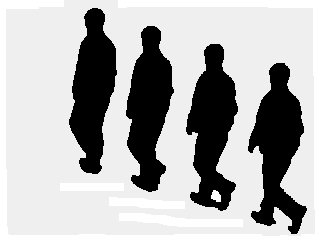
Our aim is to reconstruct the 3D scene from a video sequence of moving object with a static camera. Figure 2 shows a sample of four frames taken from a video. The proposed scene reconstruction is based on the temporal information in the image plane due to the moving object in the scene and on vanishing points inferred from displacement of keypoints of rigid object in the scene. We give in section 2 the basic principle of our method. The reconstruction of all keypoints of successive frames in explained in section 3. The obtained results with synthetic data are presented and commented in section 4. We conclude this paper with some future works in section 5.


2 Basic Principle of our method
2.1 Vanishing points from joining matched keypoints in successive frames
Let be the images of two key points of a moving object in the scene located on the frame . are the corresponding 3D points of (a’,c’) (see figure 2). Let be the images of two key points of a moving object in the scene located on the frame . are the corresponding 3D points of such that are the matches of in the sense that are the images of the same moving 3D point and are the images of the same moving 3D point (see 2. If we assume that the 3D object is rigid, then , then the lines and intersect in the vanishing point associated to the direction of (see figure 2).

2.2 Positioning of key points from two frames
Without loss of generality, we explain our method using the deux dimensions of the space (the component is ignored for this explanation). This is equivalent to see the drawn figure with a top-view.
The image plane is then represented by the axis and each point is represented by its and coordinates.
Figure 3 illustrates the reconstruction process where is 3D referential such that the is principal point, axis coincides with rows, axis coincides with columns and coincides with the optical axis (L is the projection center).
We consider two frames and reflecting the motion in 3D. The key point in moves to in the frame . Let be the intersection point of the projection ray with the line passing by and parallel to . If we place the image plane parallel to such that belongs to and are aligned (see figure 3), then the segment is reconstructed as because it is parallel to with a ratio . This ration will be used in the next for the rest of reconstruction.

2.3 Positioning of key points from two frames
To locate the point , we apply the analytic geometry. Knowing that aligned and using the assumed data: focal length (equal to ), positions of in the frame , we can compute the Y-coordinate of by the equation 1 (see figure 4).
| (1) |

2.4 Reconstruction of the keypoints of the following frames
If the point moves towards in the third frame, the same principle is applied considering the start point instead of and using the vanishing point associated to the direction of . A new plane is created to which belongs, the segment is reconstructed as (see figure 5).

3 Reconstruction of all keypoints of successive frames
3.1 Summary
Each keypoint of the second frame must be located in the 3D space. The explained method applied to keypoints associated to planar 3D points of the same object will produce 3D points appertaining to the first positioned plane . To each other keypoint, a 3D point is associated appertaining to a different plane parallel to .
3.2 Algorithm
Begin
- Input: are the frames of the video sequence.
- Output: 3D position of points corresponding to each keypoint in the frame
- FOREach ,
- DO
- FOREach keypoint of the frame
- DO
- Locate the associated keypoint in the frame
- Estimate the direction of
- Compute the 3D position of the associated keypoint of the frame
- ENDFOR
- ENDFOR
4 Experiments
We give an example of 3D reconstruction of a scene where the great sphere(with blue color in figure 6) moves from (0,10,20)to (0,8,24), (2,8,22), (4,5,26). Figure 6 illustrates the reconstructed sphere (small with red color) using only from their images shown in small size in blue color The first reconstructed sphere is identical to the image (projection of the great sphere) on the first frame. The shadow presents on the gray plane helps the understanding of the 3D positioning.


Figures 712 shows a second experiment with a rotating of the 3D object (great sphere) without visualizing position of its images on the image plane. Reconstructed spheres, using only their images, and the direction of moving sphere, are represented in red color. Note that, here, we have not implemented the key features location and tracking for the computation of 3D points directions. Our aim in this paper is to give the mathematical reasoning and to show the feasibility of the proposed solution. The results of this experiment is publicly available in (myref).


5 Conclusion and Future Works
In this paper we presented a new method to reconstruct the scene from video sequence. Our goal is to develop a codec that take as input a video sequence (mp4) and visualize the moving object in 3D.
Our future works will be devoted for the improvement of this method by:
- Tacking into account non-rigid objects, the problem posed here is how to determine vanishing points.
- In the case of moving camera. In this case, the geometry reasoning must be modified.