Pushing the Physical Limits of IoT Devices with Programmable Metasurfaces
Abstract
Small, low-cost IoT devices are typically equipped with only a single, low-quality antenna, significantly limiting communication range and link quality. In particular, these antennas are typically linearly polarized and therefore susceptible to polarization mismatch, which can easily cause dB of link loss when communicating with such devices. In this work, we highlight this under-appreciated issue and propose the augmentation of IoT deployment environments with programmable, RF-sensitive surfaces made of metamaterials. Our smart metasurface mitigates polarization mismatch by rotating the polarization of signals that pass through or reflect from the surface. We integrate our metasurface into an IoT network as LLAMA, a Low-power Lattice of Actuated Metasurface Antennas, designed for the pervasively used GHz ISM band. We optimize LLAMA’s metasurface design for both low transmission loss and low cost, to facilitate deployment at scale. We then build an end-to-end system that actuates the metasurface structure to optimize for link performance in real time. An empirical evaluation demonstrates gains in link power of up to 15 dB, and wireless capacity improvements of 100 and 180 Kbit/s/Hz in through-surface and surface-reflective scenarios, respectively, attributable to the polarization rotation properties of LLAMA’s metasurface.
1 Introduction
Internet of Things (IoT) devices have achieved widespread adoption due to shrinking hardware costs and software management tools that ease installation by the end user. In recent years, a wide range of IoT devices have resulted in diverse systems including mobile devices such as smartwatches [31] and health trackers or statically deployed devices including sensors, cameras, voice assistants, and other appliance automation [14, 15]. One key property these devices share is low-cost hardware, in particular low-cost radios, allowing for a minimal consumer price point. Such devices are typically deployed by non-experts who understand neither their home’s wireless environment nor the deployment considerations that govern wireless performance. Devices are typically deployed in a configuration that is well-suited for a particular application or use-case, but may not be the ideal placement in terms of communications performance. This combination of cheap hardware and non-ideal network topology results in significant opportunities to improve wireless performance.
One source of performance degradation in such deployments is a significant power loss caused by a polarization mismatch [13, 32] between a low-cost dipole antenna on an IoT device and antennas on a Wi-Fi access point (AP)—in higher performance devices (i.e., mobile handsets) this loss is usually mitigated through the use of circularly polarized or dynamically-switched linearly polarized antennas in different orientations. Low-cost IoT devices instead use one cheap, linearly polarized dipole antenna that results in weak, fragile links between transmitters and receivers. In addition to misaligned stationary devices, mobile devices such as wearables can suffer from dynamic antenna misalignment as a user swings their arm, for example, as Figure 1 illustrates. This effect can be significant: microbenchmark experiments show that moving between orthogonal and aligned relative antenna polarization results in dB of power variation at the receiver, for both the low power Wi-Fi link between an Arduino equipped with an ESP8266 module [19] and an 802.11g Wi-Fi AP [5] shown in Figure 2 (a), and for a Bluetooth link between a smartwatch [1] and a Raspberry Pi 3 [36] shown in Figure 2 (b).


In this work, we specifically investigate how to change the effective relative orientation of antennas at the communication endpoints, without hardware modifications to the endpoints themselves. Achieving this objective would allow us to maintain a low bill of materials cost for IoT wireless communications components, and significantly improve the performance for existing off-the-shelf devices. Our approach to changing effective polarization alignment hinges instead, on changing the radio propagation environment itself, with a Low-Power Lattice of Actuated Metasurface Antennas (LLAMA), a tunable smart surface made with inexpensive metamaterials [41, 39]. LLAMA is deployed in the radio environment near the IoT endpoints, and is able to change the polarization of incident waves as they travel from sender to receiver. As we show in this paper, the LLAMA substrate can be programmed dynamically to effect just the right amount of polarization rotation needed to help the ongoing communication between nearby endpoints. LLAMA follows the PRESS [43] approach, which was the first to outline a vision of programmable radio environments along with a preliminary experimental setup that validates the feasibility of change the perceived channel at the communication endpoints.
Designing a metasurface in the GHz ISM band requires us to overcome significant challenges. First, longer wavelengths in the GHz band require larger and thicker metasurface substrates, which can attenuate the incident signal significantly. While an inefficient structure could rotate polarization, losses would dominate and the structure would attenuate the incident signal, hampering communication. Therefore, the metasurface structure needs to be optimized for low transmission loss. Second, since we aim to realize pervasive deployments of these structures, we need to develop materials that are low cost, avoiding high performance but relatively expensive RF materials commonly used in other implementations of metasurfaces. Overcoming both of these challenges results in a pervasively deployable substrate that can compensate for losses between different endpoint pairs.
Indeed, naively replacing a high performance substrate (i.e., Rogers 5880 [38]) with a low-cost substrate (i.e., FR4 [20]) results in higher transmission loss due to FR4’s inherent physical properties; this in turn significantly attenuates power at the receiver, reducing link throughput and communication distance. To deal with this problem, we optimize the metasurface structure to ensure the overall system has both low transmission loss, as well as a scalable price point. Specifically, we choose a cheap material (FR4) as the substrate, use a minimum number of substrate layers for the required bandwidth, and minimize the thickness of each layer to significantly reduce the losses associated with FR4.
To enable real-time polarization optimization, a receiver must report received power to a controller which in turn rotates polarization by modifying a pair of bias voltages. We provide a novel method to estimate the polarization rotation angle induced by the metasurface which can vary with link distance—understanding this mapping can enable rotation sensing and tracking.
Contributions. To summarize, LLAMA is the first system that leverages an inexpensive RF substrate to optimize the radio environment in real time, thereby avoiding signal losses caused by polarization mismatch, and thus enables higher quality communication links between IoT devices. In this work, we optimize a metasurface structure based on microwave attenuation theory and achieve comparable polarization tunability to a similar system that uses relatively expensive materials. We validate a proof-of-concept implementation of LLAMA for both communication and sensing with comprehensive experiments. Our results show that LLAMA enables polarization rotation within , improves the signal strength by dB (transmission) and dB (reflection) with respect to mismatched antenna polarizations. LLAMA also holds great potential to enhance sensing applications, as demonstrated in § 5.2.2.
2 A Polarizing View of Wireless
Electromagnetic polarization describes the parametric trajectory of the electric and magnetic field vectors of a planar electromagnetic wave as it propagates through space. The polarization of RF wave propagation is a fundamental characteristic of wireless communication, but it has not received as much attention as issues like multipath fading and interference. An antenna constrains outgoing or incoming RF propagation to a particular plane. Therefore, communication is only possible if the signal propagation planes at both the transmitter and the receiver are well aligned.
Polarization loss. One challenge in mobile wireless communication links is the significant power loss due to polarization mismatch. Three examples of various transmitter antennas and their associated far-field electric fields are depicted in Figure 3. If the signal is being received by a horizontally polarized receiver antenna, it will be polarization matched to the transmitter antenna with horizontal linear polarization and the power received will primarily be a function of the transmit power and free space path loss. If the transmitter antenna is rotated in space, the received signal will continue to degrade due to polarization mismatch to the point where the very little signal is received when the antennas are completely mismatched with orthogonal polarizations. The signal loss is less when one of the antennas is circularly polarized 11 1 A theoretical dB degradation in coupling due to polarization mismatch will also occur when one of the antennas is circularly polarized while the other is linearly polarized..
As shown in Figure 2, polarization mismatch can be debilitating for IoT devices. Higher performance devices such as mobile phones use switched antennas or circular polarized antennas to mitigate polarization mismatch, but low-cost IoT devices like smartwatches typically have a single low-quality antenna.

Correcting polarization mismatch. Intuitively, polarization mismatch can be corrected by rotating the polarization of the signal before it arrives at the receiver. Here we show the mathematical foundation of polarization rotation.
In general, the polarization state of radio waves can be described by a Jones vector . Consider a plane perpendicular to the direction of signal propagation. Any polarization state can be represented by two orthogonal components in that plane (i.e., projected onto the and axes) with different amplitude and phase. The Jones vector is [28]:
| (1) |
where and represent the and polarized signal components respectively.
When a manipulation surface is aligned with the x-y coordinate axis, the Jones matrix is defined as [28]:
| (2) |
where is a phase delay between the and axes. If the surface is rotated counterclockwise by a degree of , the Jones matrix becomes [28]:
| (3) |
where is a rotation matrix.
In systems with multiple layers of polarization manipulation surface between the incident wave and outgoing wave, the outgoing Jones vector is obtained by multiplying the Jones vector of incident wave with the Jones matrix of each surface layer [28]:
| (4) |
where is a Jones matrix, representing the surface.

3 System Design
In this section, we introduce the LLAMA architecture (§ 3.1) and illustrate the properties of the metasurface hardware with HFSS simulation results (§ 3.2). Next, we illustrate our approach towards actuating polarization angle in real-time by manipulating bias voltages for the polarization rotator (in § 3.3). While the primary goal of LLAMA is to enhance signal quality between two endpoints, it can also be used for orientation sensing, which requires estimating relative polarization rotation between endpoint; § 3.4 describes a technique for this purpose.
3.1 System Overview
LLAMA is a low power system that is designed to reduce significant wireless signal loss caused by polarization mismatch between the transmitter and receiver. As shown in Figure 4, the signal from a mismatched transmitter arrives at the receiver with a lower loss when the intermediate wall includes a polarization rotator. LLAMA has the ability to improve the communication quality and extend the sensing range in the widely used ISM frequency band.
An overview of our system architecture is depicted in Figure 5 and consists of these four elements:
Metasurface. The metasurface used in LLAMA is a polarization rotator implemented using a low-cost FR4 substrate; the polarization rotator is tunable and uses biasing voltages within phase shifters in both the and axes to define a rotation angle. The metasurface is deployed in a structural element (i.e., wall) and influences wireless signals that reflect from or propagate through the metasurface.
Centralized controller. A centralized controller observes the power measured at a receiver and uses a search algorithm to determine a set of bias voltages that maximize received signal power by finding the optimal rotation angle that achieves a polarization match between the antennas at the endpoints.
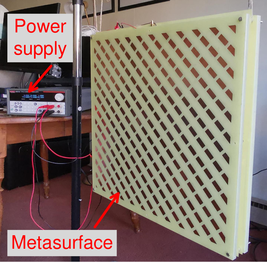
Power supply. The bias voltages used to tune the metasurface are set with a programmable DC power supply. By synchronizing the power supply output with the receiver, we can manipulate the polarization rotator with an optimal rotation angle in real time, with a rotation that maximizes signal power. Two bias voltages are needed for the phase shifters in the and axes; while bias voltages as high as V are needed, the metasurface draws only nA of current. In future implementations, a circuit that generates these bias voltages could be integrated directly on the metasurface.
Endpoints. The endpoint receiver reports its received signal strength to the controller, which then determines how to actuate the metasurface by manipulating the two bias voltages.

3.2 Metasurface Architecture
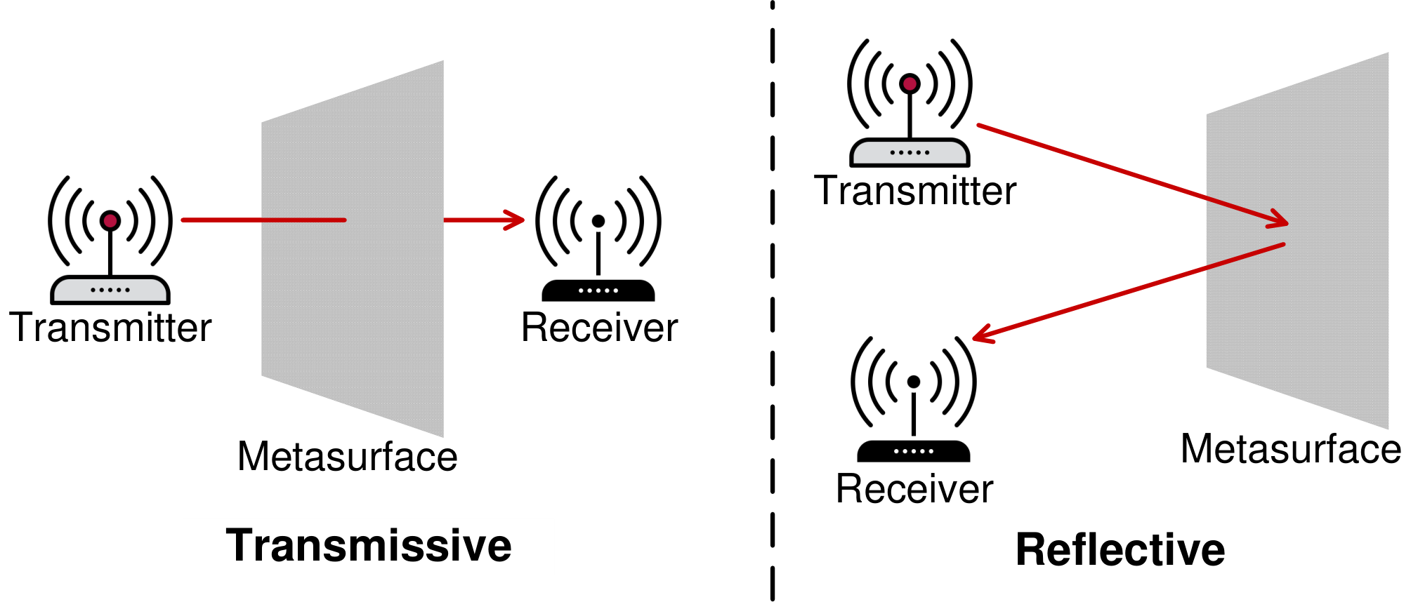
Tunable metasurfaces are implemented as layered structures that consist of copper patterns printed on controlled dielectric substrates; these layers perform different functions that reflect, bias, or guide EM waves. A transmissive metasurface uses a biasing network sandwiched between or adjacent to waveguide layer(s) to modify the transmissive signal properties in a controlled manner. In contrast, a reflective metasurface uses a metallic plane as one of its layers, where the signal passes through a wave guide layer and a biasing layer, and reflects from the metallic plane in the same relative direction with a different angle of departure. Depending on the bias voltages used LLAMA can operate in either a transmissive or reflective mode.
Cost-effective metasurface design. Our design was inspired by a GHz design [45], and we calculate the correct geometries of circuit elements for GHz instead based on the impedance matching.
To achieve polarization rotation for both x-polarized and y-polarized waves, we construct a polarization rotator consisting of a tunable birefringent structure (BFS) placed between two quarter wave plates (QWP [17]. The QWPs are rotated by and with respect to the BFS, which causes the phase delays for two orthogonal polarizations differ by . The Jones matrices of the two QWPs can be expressed as:
| (5) |
| (6) |
The tunable BFS is a transmissive metasurface that can rotate the polarization of the and axes, independently. The Jones matrix of the BFS is:
| (7) |
where is the transmission phase as the signal passes through the BFS, irrespective of initial polarization orientation, while represents the transmission phase difference between the and polarizations, which can be adjusted by manipulating the biasing voltages of the and axes as shown in Figure 5. The entire Jones matrix of the polarization rotator is:
| (8) | ||||
In summary, the proposed structure can rotate the polarization of a wave by rotation degrees, according to the rotation matrix presented in Equation (3).

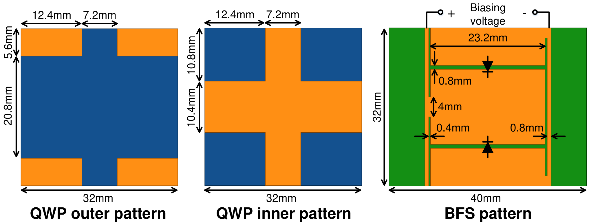
In Figure 6 (a) we show the microstrip geometries used in our metasurface design. The metasurface consists of a tunable BFS (layers 2 and 3 in Fig. 6(a)) placed between two QWPs (layers 1 and 4 in Fig. 6(a)) rotated with respect to the BFS. The BFS includes two birefringent boards rotated by with respect to each other, each board acts as a phase shifter that supports different polarization rotations by manipulating the bias voltages ( and ) of integrated varactor diodes (black) along and axes. The metallic patterns (orange) plated on the substrate boards (green and blue) act as admittance components.
We next consider the transmission efficiency () of and axis polarized signals, as that is among the most important performance metric of the overall metasurface design. Higher transmission efficiency indicates better performance. For a two-port network as shown in Figure 7, the amplitude (normalized voltage) of incoming waves ( and ) and the outgoing waves ( and ) are given by [35]:
| (9) |
where and are the normalized voltage of port and port , and are the normalized current of port and port , is the matched impedance. The scattering matrix relates the incoming waves to the outgoing waves as [35]:
| (10) |
and are reflection coefficients, and are transmission coefficients. Then the transmission efficiency can be calculated according to the following equation [35]:
| (11) |
where is obtained from the x-polarized component of incoming wave and the y-polarized component of outgoing wave .


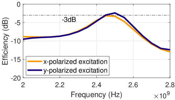
We can potentially obtain high transmission efficiency (see Figure 10) by directly scaling the circuit geometry of an existing GHz design [45] to GHz, but a key limitation is its use of an expensive, low-loss dielectric substrate (Rogers 5880) [45]. While this material achieves high transmission efficiency, it is cost prohibitive at scale. Instead, we choose a commodity FR4 substrate and characterize the behavior of the FR4 structure using an HFSS simulation environment to analyze critical parameters in the GHz ISM band.. The key problem is that FR4 ( dielectric loss tangent) causes much larger signal loss than Rogers 5880 ( dielectric loss tangent), and thus severely decreases the transmission efficiency, as shown in Figure 10.
To reduce transmission loss, we simplify the structure of the tunable phase shifter layers, and decrease the thickness of FR4 by replacing it with an air gap since the dielectric loss tangent of air is 0. By comparing Figure 10 and Figure 10, we can see that our optimized structure made of cheap FR4 can achieve comparable transmission efficiency to more complex structures and expensive materials. We use fewer (i.e., two) phase shifting layers made with thinner substrate; since the supported bandwidth of a phase shifter changes approximately linearly with the transmission line length, that is, the thickness of the substrate. Suppose the thickness of substrate is , the bandwidth can be represented as below [35]:
| (12) |
where is the design center frequency of phase shifter, is the maximum tolerable reflection coefficient, and are input impedance and load impedance, respectively. Our design achieves ( MHz of bandwidth with efficiency dB), which is wider than the target ISM frequency band that has less than MHz of bandwidth.

Estimating Polarization Efficiency. A voltage controlled capacitance is used to actuate the tuning of the X and Y planes — here we use an x-polarized incident wave as an example to show the polarization rotation results. The transmission efficiencies of the simulated frequencies under various voltage combinations are shown in Figure 11, which are always higher than dB in the GHz ISM frequency band. The other set of measurements looks at how the polarization angle can be controlled by adjusting the lumped tuning capacitance used for the and axis biasing layers. Varying this capacitance from pF to pF for both the and axes resulted in a polarization rotation angle that varied between and (see Table 1). We have also simulated the polarization rotator structure in the MHz band used for RFID and found comparable performance after additional scaling.
| (∘) | ||||||||
|---|---|---|---|---|---|---|---|---|
| 2 | 3 | 4 | 5 | 6 | 10 | 15 | ||
| 2 | 11.6 | 26.1 | 36.8 | 41.0 | 44.3 | 48.3 | 48.7 | |
| 3 | 6.5 | 12.4 | 26.6 | 32.2 | 35.2 | 38.6 | 39.2 | |
| 4 | 23.0 | 4.9 | 10.9 | 17.3 | 20.8 | 25.0 | 25.6 | |
| 5 | 27.0 | 9.3 | 7.4 | 14.0 | 18.0 | 22.6 | 23.2 | |
| 6 | 41.8 | 25.0 | 7.9 | 2.1 | 4.2 | 10.2 | 10.7 | |
| 10 | 45.8 | 30.0 | 13.7 | 7.9 | 2.8 | 5.1 | 5.6 | |
| 15 | 48.2 | 33.1 | 18.2 | 12.9 | 7.3 | 1.9 | 2.0 | |
end for
end if


3.3 Metasurface Control
To enable polarization rotation control, we need to change the capacitance of the and axis phase shifters; in our design this is accomplished by changing the bias voltage of the integrated varactor diodes (SMV1233) in the and polarities, which in turn changes their capacitance and thus phase. All diodes in a given polarization are controlled using the same bias voltage; we use a programmable power supply for this purpose and these voltages can be as high as V to account for errors induced during fabrication and assembly, hence we set V as the voltage sweep range of the and axes. The power supply is connected to a desktop computer through a USB interface, and is controlled by a Python script that uses the Virtual Instrument Software Architecture (VISA) standard with a maximum voltage switching frequency of Hz. With a voltage step of V, the full scan across both X and Y axes takes seconds, which prevents real-time applications.
To reduce the sweep time, we start with a coarse-grained voltage sweep then increase the resolution of control as summarized in Algorithm 1. Specifically, we define as the number of iterations, and as the number of voltage adjustments per iteration. The time cost in iteration is . We empirically set to and to , according to the switching speed and the voltage resolution of the programmable power supply. After iterations across the and axes, we can determine the optimal voltage combination to yield the strongest received signal.
Synchronization between rotator and receiver. For real-time polarization correction and communication link optimization, it is necessary to correlate the currently received sample with the bias voltage state, so that we can determine an optimal voltage combination that enables the strongest received signal power. In our prototype, for simplicity we directly connect the receive antenna to the voltage supply, which allows us to assume the voltage switch speed and receiver sampling rate have a constant relationship over time. This allows us to relate received signal samples with the voltage state of LLAMA at a given time instance. A full implementation can have the receiver explicitly send channel state information to the controller, as in previous work [29, 18].
One important aspect of the design we want to highlight is that the leaking current of our metasurface is as low as nA, which means the metasurface does not need a large battery or significant power from the AC mains to keep it powered; it can maintain operation with a modestly sized capacitor.


3.4 Polarization Rotation Degree Estimation
Besides increasing SNR, we can also sense the relative orientation of the two endpoints with LLAMA. Here we present our approach for rotation angle estimation according to the received signal power reported by the endpoint receiver, no matter the transmitter-receiver distance; as distances between the transmitter and receiver become comparable to the size of the metasurface (See Figure 4), a fraction of the signal can bypass the metasurface without polarization rotation, and this results in less overall perceived rotation at the receiver. According to our benchmark experimental result plotted in Figure 12 (a), we observed that the received signal power (before the dBm conversion) can be approximated as a linear change with the orientation difference between transmitter and receiver. When we perform measurements across a full voltage sweep, we can get the maximum potential improvement to signal power. To obtain the polarization rotation angle for an unknown transmitter-receiver distance (i.e., the potential power improvement over an orientation sweep is unknown), the key is determining the minimum and maximum polarization rotation angles. We take the following steps.
Step 1: Fix the receiver at the same orientation with the transmitter, by rotating the receiver to find an orientation where the received power is largest.
Step 2: Sweep across voltage combinations and corresponding to min and max powers, respectively (i.e., parallel and orthogonal polarizations).
Step 3: Set the voltage state to the two searched combinations, respectively. At each voltage state, rotate the receiver by to find the new orientation where the power is strongest. The two new orientations of and can be defined as and as shown in Figure 12 (c). The differences of the receiver’s initial orientation and two new orientations and correspond to the minimum and maximum polarization rotation angles, respectively.
4 Implementation and Experimental Setup
Metasurface. We fabricated the metasurface with a total surface area of and a thickness of cm, including functional units (Figure 13 (a-d)). The biasing voltages of the metasurface are provided by a programmable power supply (TektronixSeries 2230G [6]) through two DC channels, as shown in Figure 13 (a). LLAMA utilizes varactor diodes (SMV1233), costing each. The total cost of LLAMA for all PCB layers is , resulting in a total cost of . Given economies of scale, the unit cost can be reduced to when there are more than units per PCB.
Experimental setup. For controlled experiments, we utilize one USRP N210 software-defined radio with a UBX-40 daughterboard as the ISM signal transceiver, operating at a default center frequency of GHz. The transmitter and receiver antennas are separated by a specified distance. We experiment with both directional [9] and omni-directional antennas [3]. We configure and control the USRP using the GNU radio software development toolkit [22] run on a PC. The transmitter continuously transmits a cosine waveform over KHz, while the sampling rate of the receiver is MHz. We also evaluate LLAMA using low-cost Wi-Fi and Bluetooth devices (the same setup as benchmark experiments as shown in Figure 2). Additionally, we perform an experiment with a pair of GIGABYTE mini-PCs [4] with Intel 5300 wireless cards, to evaluate performance over a larger frequency range (i.e., MHz, including OFDM subcarriers).
We perform both through-surface (transmissive) and surface-reflection (reflective) experiments as shown in Figure 13 (e). In transmissive experiments, the metasurface is placed between the transmitter and receiver. In reflective experiments, the transmitter and receiver are placed on the same side of the metasurface. In each experiment, the baseline received signal power without the metasurface is measured by averaging seconds of received samples, and the maximum signal power with the metasurface is obtained after a fast sweep of voltages as detailed in § 3.3. To avoid multipath effects confounding the performance behavior of LLAMA, we cover the test area with RF absorbing material, and use directional antennas by default in USRP-based experiments.
5 Evaluation
In this section, we conduct extensive experiments to evaluate the performance of LLAMA. We first answer how metasurface improves the transmissive signal power in polarization mismatch setup. Then we analyze the relationship between signal enhancement induced by the metasurface across a number of parameters including transmitted power, multipath effect, antenna directionality and operating frequency. We also evaluate LLAMA’s performance for practical low-cost IoT communication links. In addition, we validate LLAMA’s ability to enhance a reflected signal, and demonstrate the influence of the proposed metasurface structure for sensing.
Performance metrics. We measure signal strength at the receiver as our performance metric, since this directly characterizes the benefit of polarization rotation. An increase in the received power usually translates to a throughput improvement. While it is common to measure link throughput directly, the size limit of our current prototype makes it challenging to characterize link throughput in diverse settings.


5.1 Transmissive Operation
5.1.1 Transmissive Signal Enhancement
To verify LLAMA’s ability to rotate the polarization of transmissive signals, we conduct experiments with the metasurface under different transmitter-receiver (Tx-Rx) distances (from cm to cm by half wavelength steps of cm). The transmitter and receiver are placed orthogonally such that they are in a mismatched polarization configuration. In each experiment, we measure the received signal power across a full sweep of voltage combinations (both and vary from V). Figure 14 (a-g) show how the received signal power changes with different voltage combinations at each Tx-Rx distance and how the maximum achieved rotation angle diminishes as the distance becomes comparable to the size of the surface. The signal power changes significantly with changes in biasing voltage. We also find the mapping between these voltages as the rotation shifts gradually with respect to Tx-Rx distance. Figure 14 (h) shows the polarization rotation degree measured by the proposed method in § 3.4. We find that the metasurface can rotate the polarization over a range of , which allows the metasurface to correct for a significant amount of mismatch. To understand the signal improvements provided by the metasurface, we also measure the signal power in mismatch configuration with no metasurface present as a baseline. By comparing the results with and without the metasurface as depicted in Figure 16, we can see that the metasurface enhances the transmissive signal power by up to dB, which extends the potential transmission distance by up to according to the Friis equation [21].
5.1.2 Performance Benchmarks
Validating operational bandwidth. In order to evaluate LLAMA’s performance over the entire ISM frequency band, we conduct experiments that vary the operating frequency from GHz to GHz by steps of GHz. We measure the maximum signal power with and without the metasurface. From the results shown in Figure 16, we can see that LLAMA enables dB signal enhancement across the entire ISM frequency band, when compensating for polarization mismatch (orthogonal antenna orientation). This indicates that LLAMA has potential for optimizing IoT communication links with protocols including Wi-Fi, Bluetooth and Zigbee.


Impact of incident power on performance gains. In this experiment, we sweep through transmit power settings to understand how incident power affects the performance improvement (measured in terms of channel capacity enhancement) provided by the metasurface — lower transmit powers could potentially be dominated by loss within the metasurface. The capacity is calculated according to the SNR measurement and channel bandwidth. We perform experiments with both directional [9] and omnidirectional [3] antennas on the transceiver. Figure 18 shows that the capacity initially increases slowly with transmitting power for both the directional and omnidirectional antennas, due to the loss induced by the metasurface; the “cut-off" transmit power for the metasurface to provide benefit is as low as mW.
Impact of multipath. In these experiments we seek to understand the impact of multipath propagation on LLAMA’s performance. We perform experiments in an indoor lab environment without absorber material. We also measure the channel capacity by using two types of antennas at different transmit power. By comparing the results of Figure 18 with Figure 18, we find that for a directional antenna, the metasurface can still contribute similar capacity improvements to without multipath. However, the results from omni-directional antennas are different – when the transmitted power is lower than mW, the metasurface will no longer enhance the passing signal, and in fact degrade the channel capacity. Directional antennas “concentrate” the signals through the metasurface, so the incident power is higher and the metasurface can let more power through; omni-directional antennas do not send as much incident power to the metasurface, so the enhancement from polarization matching may not compensate for the loss through the surface. For that reason, the metasurface can effectively block out some weaker multipath components, and therefore the endpoint receiver will not get constructive interference from these multipath components. In that sense, it is possible the metasurface can reduce performance.
5.1.3 Experiments with Low-cost IoT Devices
Finally, we evaluate LLAMA’s performance with low-cost IoT devices. We perform tests with conventional Wi-Fi and Bluetooth links. The Wi-Fi link is between a Wi-Fi router and an Arduino with a low-cost ESP8266 module, and the Bluetooth link is between a Huawei Watch and a Raspberry Pi 3. From the signal power distributions shown in Figure 20, we find that for the Wi-Fi link, LLAMA creates around dB signal power improvement in a mismatched polarization setup, which looks similar to the matched configuration depicted in Figure 2 (a). While the improvement for the Bluetooth link is lower, this is expected according to the result shown in Figure 18 (a), which indicates the amount of signal quality change that can be affected by LLAMA depends on the incident power level at the metasurface. Nevertheless, we believe LLAMA could still help Bluetooth receivers when the transmitter is a higher-power device, such as a mobile handset.
We next study how LLAMA performs when operating across a wider band channel. Most Wi-Fi transmissions today leverage OFDM over MHz. To answer this question, we leverage GIGABYTE mini-PCs equipped with conventional off-the-shelf Intel 5300 wireless cards as transceivers to conduct an experiment – the center frequency and bandwidth are GHz and MHz, respectively. Figure 20 shows the channel gain measurements with and without the metasurface in a mismatched configuration. The results show that the overall channel gain is improved, but the enhancement of individual subcarriers are different given the specific bias voltages used for the metasurface; this is consistent with the simulation results shown in Figure 11. The subcarrier channel gains with the metasurface are more consistent over frequency than without. We believe the presence of LLAMA blocks weak multipath signal components that traverse longer paths and tend to exhibit frequency-selectivity more, and the remaining components are aligned through polarization rotation.


5.2 Reflective Operation
5.2.1 Reflective Signal Enhancement
In addition to evaluating transmissive configurations, we also look at LLAMA’s effect on reflected signals. We place the transmitter and receiver on the same side of the metasurface, and separate the transmitter and receiver by cm. We perform experiments at different Tx-metasurface distances by moving the metasurface along the vertical line of the transceiver pair. Figure 23 shows the maximum received signal power and channel capacity with the metasurface , as well as the baseline measurements without the metasurface in a mismatched configuration. These results show that LLAMA also has a positive impact on the reflection scenario—the signal power and capacity can be improved with respect to mismatch by as much as dB and kbps/Hz, respectively. However, the signal power difference over voltage combinations (see Figure 21) is much smaller than that in the transmission scenario. We believe this is because the rotation will be cancelled after reflection.
5.2.2 Employing LLAMA for Sensing
Based on the reflective configuration, we conjecture that LLAMA can be utilized to enhance sensing. To validate this, we consider human respiration detection as a case study to test LLAMA’s potential. In this experiment, the metasurface is placed m away from the center of the transceiver pair, the human subject is located on the side between the transmitter and the metasurface. First, we remove the metasurface and reduce the transmitting power to where the human subject’s respiration can no longer be detected from the received signal. Then we introduce the metasurface at the predetermined location, and measure the received signal strength. The detection results with and without the metasurface are plotted in Figure 23. It is clear that the metasurface can enhance the reflected signal and allow the target’s respiration rate to be detectable under a low transmit power configuration ( mW). We believe that LLAMA can also be extended to other low SNR sensing applications [50, 23].
6 Discussion and Future Work
Scaling to a dense IoT deployment. This work marks the first step towards mitigating polarization issues for individual communication links with a LLAMA prototype. Next, we plan to scale up the size of the metasurface for a larger deployment and explore more challenging multi-link scenarios. When there are multiple IoT devices in different polarization orientations, tuning the signal polarization can lead to a new form of polarization reuse or access control and improve the network throughput of a dense IoT deployment.
Adapting to device mobility. The current search time for optimal voltage is limited by the switching speed of the commodity power supply we used, hence there is still a latency issue in mobility scenarios. In the future, we will look at methods that can speed this up once the relative antenna orientations are determined and then track the changes.
7 Related Work
Broadly speaking, our work is related to work in three areas:
Endpoint optimizations. Most efforts for improving communication quality focuses on controlling the endpoints themselves. For instance, Multiple Input, Multiple Output (MIMO) links leverage multiple antennas to exploit spatial diversity at a sub-link level, while Multi-User MIMO exploits spatial diversity at an inter-link level [24, 25]. Massive MIMO introduces many more antennas at an access point than both radio chains and users, so that the AP may search for a set of antennas that forms a well-conditioned MIMO channel to those users [40, 34, 47]. However, these approaches are fundamentally limited if the cause of performance loss is antenna polarization mismatch between endpoints. At the endpoints, the only directly relevant mitigation strategies are to use either circularly polarized antennas or multiple linearly polarized antennas. Once the antennas are fixed, not much can be done about polarization match at the endpoints. Using an antenna array like massive MIMO can enhance the received signal power, but without directly addressing the polarization issue.
In contrast, an approach that changes the radio environment itself (e.g., deploying low-cost reflectors) offers the possibilities to increase the number of degrees of freedom.
Environment-based optimizations. Previous work on radio environment optimizations fall into two categories: phase-based and amplitude-based. Initial attempts of phase based approaches such as leveraging static mirrors [52] or programmable phased-array reflectors [7, 8, 42] are in the ability of generating constructive propagation paths. These methods focus on millimeter wave links on high frequency bands (i.e., GHz and above). More generally, several proposals argue for dynamically reconfiguring the radio environments [43, 11, 37, 12, 48, 44, 30]. Specifically, recent prototypes manipulate the signal propagation behavior in the 2.4 GHz band, by using a large array of inexpensive antennas [43, 29, 18] or conductive surfaces [16] as phase shifting elements. These systems align phase elements according to a channel decomposition. Amplitude-based designs, such as RFocus [10], sidestep the difficulty in measuring phase. Based on the signal amplitude measurements from the receiver, RFocus configures the signal to either pass through or reflect from the surface element by setting the “on” or “off” state of each element, so that the transmitted signal is focused at the intended receiver.
Orthogonal to prior work that aligns multiple paths to achieve beamforming effects or improve spatial multiplexing efficiency, LLAMA optimizes low-cost IoT communication links by specifically overcoming the pervasive issue of polarization mismatch that affects both single and multi-path communication.
Metamaterials. Metamaterials are an earlier, more general form of metasurfaces that are constructed in 3D rather than 2D. These are artificially constructed with special properties. Recent work in the applied physics community has developed metamaterials that can directly alter existing signals in the environment itself, such as creating materials with a negative refraction index [27] and engineering complex beam patterns [33]. Other work has verified the feasibility of leveraging metamaterials to change the signal polarization [26, 51, 46, 45, 49]. With a biasing network, different voltages are provided to diodes integrated on the metasurface for rotating the polarization of a transmitted wave. While these designs have shown great promise in controlled experiments that quantify performance in a higher frequency band (i.e., GHz), they were constructed using expensive, low loss substrate materials such as Rogers or F4B. Furthermore, they have not been integrated into an end-to-end system that optimizes signal paths in real time.
In contrast, we present an end-to-end system incorporating the structure of a metasurface design for the GHz ISM band using cheaper, but higher loss FR4 material, and specifically control the structure’s polarization rotation to optimize the communication link between a pair of devices.
8 Conclusion
This paper highlights the under-appreciated issue of polarization mismatch for low-cost IoT devices that are physically limited to employing a single low-quality antenna. We present LLAMA, a system designed to mitigate the polarization mismatch without hardware modifications to the endpoints. LLAMA is capable of manipulating the polarization state of the signal arriving at the receiver with a tunable metasurface structure made with cheap material. It can optimize the communication quality in real time, and enhance the performance of sensing applications.
Acknowledgement
We thank our shepherd Fadel Adib, and the anonymous reviewers for their helpful feedback in improving the paper. This work is supported by the National Science Foundation under Grant Nos. CNS-1617161, CNS-1763212 and CNS-1763309, the National Natural Science Foundation of China under Grant Nos. 61672428 and 62061146001, the ShaanXi Science and Technology Innovation Team Support Project under Grant No. 2018TD-026. Any opinions, findings, and conclusions or recommendations expressed in this material are those of the author(s) and do not necessarily reflect the views of the National Science Foundation.
References
- [1] Huawei watch. Website, 2015.
- [2] Comxim 360 degree photography turntable. Website, 2020.
- [3] Highfine 2 x 2.4 GHz 6 dBi indoor omni-directional Wi-Fi antenna. Website, 2020.
- [4] Mini-pc barebone (brix). Website, 2020.
- [5] Netgear n300 wifi cable modem wireless router. Website, 2020.
- [6] Series 2230G High Power, 3-Channel Programmable Power Supplies. Website, 2020.
- [7] O. Abari, D. Bharadia, A. Duffield, D. Katabi. Cutting the cord in virtual reality. Proceedings of the 15th ACM Workshop on Hot Topics in Networks, 162–168, 2016.
- [8] ——. Enabling high-quality untethered virtual reality. NSDI, 531–544, 2017.
- [9] Alfa Network APA-M25 2.4+5GHz Dual Band Indoor Antenna. Website, 2020.
- [10] V. Arun, H. Balakrishnan. RFocus: Practical beamforming for small devices. NSDI, 1–12, 2020.
- [11] E. Basar, M. Di Renzo, J. De Rosny, M. Debbah, M. Alouini, R. Zhang. Wireless Communications Through Reconfigurable Intelligent Surfaces. IEEE Access, 7, 116,753–116,773, 2019.
- [12] E. Björnson, L. Sanguinetti, H. Wymeersch, J. Hoydis, T. L. Marzetta. Massive MIMO is a Reality – What is Next? Five Promising Research Directions for Antenna Arrays. Digital Signal Processing, 94, 2019.
- [13] S. M. Bowers, A. Safaripour, A. Hajimiri. Dynamic polarization control. IEEE Journal of Solid-State Circuits, 50(5), 1224–1236, 2015.
- [14] J. Chan, S. Raju, R. Nandakumar, R. Bly, S. Gollakota. Detecting middle ear fluid using smartphones. Science translational medicine, 11(492), eaav1102, 2019.
- [15] J. Chan, T. Rea, S. Gollakota, J. E. Sunshine. Contactless cardiac arrest detection using smart devices. NPJ digital medicine, 2(1), 1–8, 2019.
- [16] J. Chan, A. Wang, V. Iyer, S. Gollakota. Surface mimo: Using conductive surfaces for mimo between small devices. Proceedings of the 24th Annual International Conference on Mobile Computing and Networking, 3–18, 2018.
- [17] J. A. Davis, D. E. McNamara, D. M. Cottrell, T. Sonehara. Two-dimensional polarization encoding with a phase-only liquid-crystal spatial light modulator. Applied Optics, 39(10), 1549–1554, 2000.
- [18] M. Dunna, C. Zhang, D. Sievenpiper, D. Bharadia. Scattermimo: enabling virtual mimo with smart surfaces. Proceedings of the 26th Annual International Conference on Mobile Computing and Networking, 1–14, 2020.
- [19] ESP8266 Wi-Fi Main Board. Website, 2020.
- [20] Standard FR4 TG135 Datasheet. Website, 2020.
- [21] Friis transmission equation. Website, 2020.
- [22] GNURadio. Website, 2020.
- [23] U. Ha, J. Leng, A. Khaddaj, F. Adib. Food and liquid sensing in practical environments using rfids. NSDI, 1083–1100, 2020.
- [24] E. Hamed, H. Rahul, M. A. Abdelghany, D. Katabi. Real-time distributed MIMO systems. SIGCOMM, 412–425, 2016.
- [25] E. Hamed, H. Rahul, B. Partov. Chorus: Truly distributed distributed-MIMO. SIGCOMM, 461–475, 2018.
- [26] J. Hao, Y. Yuan, L. Ran, T. Jiang, J. A. Kong, C. Chan, L. Zhou. Manipulating electromagnetic wave polarizations by anisotropic metamaterials. Physical review letters, 99(6), 063,908, 2007.
- [27] I. Kourakis, P. Shukla. Nonlinear propagation of electromagnetic waves in negative-refraction-index composite materials. Physical Review E, 72(1), 016,626, 2005.
- [28] B. Kress, P. Meyrueis. Digital diffractive optics: An introduction to planar diffractive optics and related technology, 2000.
- [29] Z. Li, Y. Xie, L. Shangguan, R. I. Zelaya, J. Gummeson, W. Hu, K. Jamieson. Towards programming the radio environment with large arrays of inexpensive antennas. NSDI, 285–300, 2019.
- [30] C. Liaskos, S. Nie, A. Tsioliaridou, A. Pitsillides, S. Ioannidis, I. Akyildiz. A New Wireless Communication Paradigm through Software-Controlled Metasurfaces. IEEE Communications Magazine, 56(9), 162–169, 2018.
- [31] R. Nandakumar, V. Iyer, D. Tan, S. Gollakota. Fingerio: Using active sonar for fine-grained finger tracking. Proceedings of the 2016 CHI Conference on Human Factors in Computing Systems, 1515–1525, 2016.
- [32] M. Okatan, J. Mantese, S. Alpay. Polarization coupling in ferroelectric multilayers. Physical Review B, 79(17), 174,113, 2009.
- [33] A. A. Orlov, P. M. Voroshilov, P. A. Belov, Y. S. Kivshar. Engineered optical nonlocality in nanostructured metamaterials. Physical Review B, 84(4), 045,424, 2011.
- [34] H. S. Rahul, S. Kumar, D. Katabi. JMB: Scaling wireless capacity with user demands. SIGCOMM CCR, 42(4), 235–246, 2012.
- [35] R. S. Rao. Microwave engineering. PHI Learning Pvt. Ltd., 2015.
- [36] Raspberry Pi 3 Model B+. Website, 2020.
- [37] M. D. Renzo, M. Debbah, D.-T. Phan-Huy, A. Zappone, M.-S. Alouini, C. Yuen, V. Sciancalepore, G. C. Alexandropoulos, J. Hoydis, H. Gacanin, J. de Rosny, A. Bounceur, G. Lerosey, M. Fink. Smart radio environments empowered by reconfigurable AI meta-surfaces: An idea whose time has come. EURASIP Journal on Wireless Communications and Networking volume, 2019.
- [38] Rogers corporation. Website, 2017.
- [39] N.-H. Shen, M. Kafesaki, T. Koschny, L. Zhang, E. N. Economou, C. M. Soukoulis. Broadband blueshift tunable metamaterials and dual-band switches. Physical Review B, 79(16), 161,102, 2009.
- [40] C. Shepard, H. Yu, N. Anand, E. Li, T. Marzetta, R. Yang, L. Zhong. Argos: Practical many-antenna base stations. MobiCom, 53–64, 2012.
- [41] D. Shrekenhamer, W.-C. Chen, W. J. Padilla. Liquid crystal tunable metamaterial absorber. Physical review letters, 110(17), 177,403, 2013.
- [42] X. Tan, Z. Sun, J. M. Jornet, D. Pados. Increasing indoor spectrum sharing capacity using smart reflect-array. ICC, 1–6. IEEE, 2016.
- [43] A. Welkie, L. Shangguan, J. Gummeson, W. Hu, K. Jamieson. Programmable radio environments for smart spaces. Proceedings of the 16th ACM Workshop on Hot Topics in Networks, 36–42, 2017.
- [44] Q. Wu, R. Zhang. Towards Smart and Reconfigurable Environment: Intelligent Reflecting Surface Aided Wireless Network. IEEE Communications Magazine, 58(1), 106–112, 2020.
- [45] Z. Wu, Y. Ra’di, A. Grbic. Tunable metasurfaces: A polarization rotator design. Physical Review X, 9(1), 011,036, 2019.
- [46] H. Yang, X. Cao, F. Yang, J. Gao, S. Xu, M. Li, X. Chen, Y. Zhao, Y. Zheng, S. Li. A programmable metasurface with dynamic polarization, scattering and focusing control. Scientific reports, 6, 35,692, 2016.
- [47] Q. Yang, X. Li, H. Yao, J. Fang, K. Tan, W. Hu, J. Zhang, Y. Zhang. BigStation: Enabling scalable real-time signal processing in large MU-MIMO systems. SIGCOMM CCR, 43(4), 399–410, 2013.
- [48] Q. Zhang, Y.-C. Liang, H. V. Poor. Large Intelligent Surface/Antennas (LISA) Assisted Symbiotic Radio for IoT Communications, 2020.
- [49] X. G. Zhang, Q. Yu, W. X. Jiang, Y. L. Sun, L. Bai, Q. Wang, C.-W. Qiu, T. J. Cui. Polarization-controlled dual-programmable metasurfaces. Advanced Science, 1903382, 2020.
- [50] M. Zhao, F. Adib, D. Katabi. Emotion recognition using wireless signals. MobiCom, 95–108, 2016.
- [51] Y. Zheng, Y. Zhou, J. Gao, X. Cao, H. Yang, S. Li, L. Xu, J. Lan, L. Jidi. Ultra-wideband polarization conversion metasurface and its application cases for antenna radiation enhancement and scattering suppression. Scientific reports, 7(1), 1–12, 2017.
- [52] X. Zhou, Z. Zhang, Y. Zhu, Y. Li, S. Kumar, A. Vahdat, B. Y. Zhao, H. Zheng. Mirror mirror on the ceiling: Flexible wireless links for data centers. SIGCOMM CCR, 42(4), 443–454, 2012.