acmlicensed \isbn123-4567-24-567/08/06 \acmPrice$15.00 \toappearSubmitted to UIST 2020.
![[Uncaptioned image]](2007.11199v1/figure1.png)
Romeo enables a user to transform a Minion model into a coin-stealing piggybank by selecting the mid-section of the Minion as the transformable part (a), specifying motion path for the transformed part to pick up a coin and place it in the bank (b), generating the corresponding transformable robotic arm (c) and 3D printing and installing the result (d-e).
Romeo: A Design Tool for Embedding Transformable Parts in 3D Models to Robotically Augment Default Functionality DOI: http://dx.doi.org/10.475/123_4Conference: CHI’16, May 07–12, 2016, San Jose, CA, USA
Abstract
Reconfiguring shapes of objects enables transforming existing passive objects with robotic functionalities, e.g., a transformable coffee cup holder can be attached to a chair’s armrest, a piggybank can reach out an arm to ’steal’ coins. Despite the advance in end-user 3D design and fabrication, it remains challenging for non-experts to create such ‘transformables’ using existing tools due to the requirement of specific engineering knowledge such as mechanisms and robotic design.
We present Romeo—a design tool for creating transformables embedded into a 3D model to robotically augment the object’s default functionalities. Romeo allows users to express at a high level, (1) which part of the object to be transformed, (2) how it moves following motion points in space, and (3) the corresponding action to be taken. Romeo then automatically generates a robotic arm embedded in the transformable part ready for fabrication. We validated Romeo with a design session where 8 participants design and create custom transformables using 3D objects of their own choice.
keywords
Design tool; transformables; robotic task; generative design.<ccs2012> <concept> <concept_id>10003120.10003121.10003129</concept_id> <concept_desc>Human-centered computing Interactive systems and tools</concept_desc> <concept_significance>500</concept_significance> </concept> </ccs2012>
[500]Human-centered computing Interactive systems and tools
1 Introduction
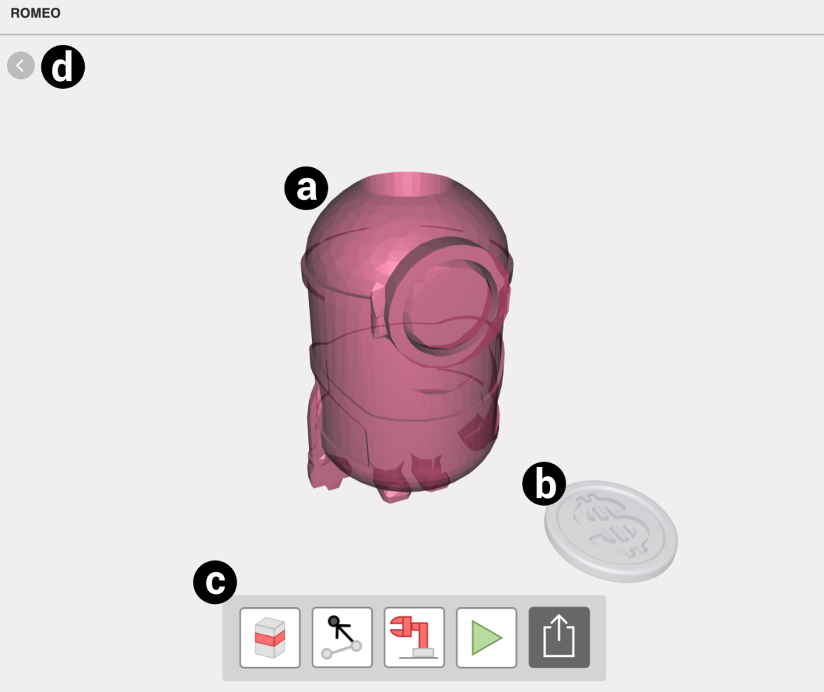
Objects that can transform its geometry and/or functionality (which we referred to as transformables) hold the promises of dynamically adapting to multiple usages by reconfiguring shapes, either automatically or via manual reconfiguration as depicted in Figure 1 with several examples.
The advent of computational design and 3D modelling tools offers the possibilities for casual makers [16] to create custom objects. However, for non-technical users, designing transformables remains challenging due to the requirements of expert-level engineering knowledge such as mechanisms and robotic design that are not provided in existing end-user oriented design tools.

Prior work focused on actuating passive objects [5, 28, 23] using attachable mechanisms, yet has not taken account how to transform given objects. Prior work that addressed transformables tends to focus on computational analysis of geometry and optimization [36, 37, 15], rather than providing design assistance to create user-defined custom transformables. Further, these approaches almost exclusively exploit geometry as the only constraint when generating a transformable design (e.g., [36]), with little consideration of obtained functionality, i.e., how a transformable can perform a user-defined task.
We present Romeo—a design tool for generating and embedding transformable parts in 3D models to robotically augment the default functionality. Figure Romeo: A Design Tool for Embedding Transformable Parts in 3D Models to Robotically Augment Default Functionality shows an exemplar workflow of Romeo: A user selects a cross section of the minion to be a transformable part (a), specifies a motion path to pick up a coin and place it in the bank (b), based on which Romeo generates the corresponding transformable robotic arm (c), which is then 3D printed and installed with motors to perform the coin-stealing task (d-e).
We conducted a design session with eight participants conducting both controlled task to replicate a task using given 3D objects (stirring spatula and sanitizing tissue box) and open-ended tasks (design a piggy bank using participant-chosen 3D model) of creating transformables. Overall, participants were able to understand and complete design using Romeo as a design tool, to define functional tasks by parts selection and motion path specification, to generate ready-to-print transformable parts for fabrication, and to assemble the parts into a fully functional transformable object.
Our main contribution is an end-user design tool that addresses both geometric and functional constraints in generating a transformable part embedded into an object’s 3D model (geometric constraint) while being able to transform and perform a user-defined task (functional constraint).
2 Related Work
Romeo provides end-users with a design tool to augment an object’s functionality by transforming a subset of the object. This goal cross-cuts three areas of prior work: (i) designing objects that can transform original shapes (ii) reality-based design tools that extract real-world information (e.g., object geometry and context) to create designs; and (iii) interactive design of robotic characters.
2.1 Computational Design of Shape-Changing Objects
Past research has explored the design of articulated objects that can actuate existing shape by transformation. Calì et al. proposed to generate assembly-free models by inserted joint configurations of an animation rig to articulate mechanical object [4]. Bächer et al. takes a skinned mesh as input and estimate the corresponding virtual articulated part segment to compute placement of the joints [2]. Ureta et al. proposes an interactive system for creating 3D printable joints with user-controlled appearance while taking into account the range of motion achievable [33]. All this work focuses largely on inserting assembly-free joints in the articulated parts given the input shapes, rather than to transform such objects away from their given shapes.
One body of research on transforming shapes is concerned with the design of reconfigurable objects. Li et al. and Garg et al. proposed computational approaches to design foldable furniture to save space while not in use [21, 12]. In this process, Boxelization helps transform a 3D object into a series of small cubes where adjacent cubes are either linearly-linked and/or fold [37]. Huang et al. explores the design and animation of the motion of transformation based on the input 3D model and target skeleton representing the desired figure [15]. Yu et al. investigates transforming the object with telescopic structures using user sketches or an arbitrary mesh as input [35]. Perhaps the most related to our work is the design approach by Yuan et al., which uses the target model and skeleton as user input to automatically generate fabricable transformable objects [36]. However, Yuan et al. only addresses the automatic generation of transformables based on input geometry constraints, but does not consider higher-level goals of the desired function as input. Across prior work, there is a lack tool support for non-expert users to create custom transformable objects.
Also, design of origami robots is also related as such robots can be initially fabricated as flat sheet then be folded into a complex 3D shapes. Schulz et al. proposed an end-to-end system for design of robots with ground locomotion [30]. Mehta et al. proposed a tool that users can create printable 3D origami-inspired robot from high-level structural and functional specification [25, 26, 27]. Romeo focuses on using existing 3D shapes with a default function and transform into another 3D shape with augmented functionality.
2.2 Reality-based Design Tools
Romeo enables end-users to define a task that the transformable part will conduct, to interact with real-world objects (e.g., picking up and depositing a coin). Existing work has explored reality-based design tools that address (i) how to design objects with kinematic and robotic features from (ii) high-level, real world context-based design goals as an input, while leaving low-level functional considerations to a generative algorithm.
Design of objects with kinematic feature that could physically interact with the real world has been a focus of many research. Obtaining an understanding of the physical world informs new ideas of augmentation, such as ‘mechanical hijacking’ first demonstrated by Davidoff et al. facilitated physical interaction with real-world object using LEGO MindStorm toolkit [8]. TrussFormer enables users to design and 3D print large-scale structures with kinematic features [19]. Grafter helps end users extract and reconstruct mechanical elements from 3D printable machines. It affords users to be aware of real-world constraints when fabricated, allowing to clean out sweeping space along with rotation axles[29]. RetroFab offers an authoring tool to scan an existing physical interface and automate its controls with an enclosure consisting of mechanical widgets and electronic devices [28]. Robiot turns legacy static objects into robots by generating 3D printable attachment mechanisms to automate physical tasks [22]. Similarly, Romeo aims at empowering end-users to create transformable parts of objects that are able to physically interact with real-world objects, given context-aware, user-defined task.
Generative design is also related to our work in that it allows users to only provide high-level information as input. Reprise invites users to express what type of action is applied to an object at a high level, and so generates adaptation for hand-held objects for easy manipulation [5]. AutoConnect promotes the automatic generation of the attachment mechanisms between two user-selected objects based on input 3D model or scanned digital model of real-world object [20]. Further incorporate users’ intent, Forte loops user input into the optimization process to create structures that meet functional requirement as well as mimic users’ sketches [6]. Patching provides a hybrid platform that scans, mills, and fabricates new components ad-hoc, to replace part of an existing object with updated user-context [31]. DreamSketch allows a user to integrate generatively designed components with the workflow of sketching [18]. In comparison, Romeo employs a hybrid approach that combines the automation of robotic feature generation as well as a generative process: users input a 3D model and specify a reality-based target task, based on which the tool generates the corresponding transformable parts.
2.3 Interactive Design of Robotic Characters
The eventual goal of Romeo is to generate functional ready-to-transform objects based on user-defined high-level specification. To achieve this, Romeo builds upon prior work that examine interactive design of robotic characters.
Megaro et al. present a design system that automates the tedious process of creating 3D-printable robotic creatures while allowing for customization for casual users [24]. Recent research focused on computational approaches for non-expert users to design animated or robotic characters by high-level motion specification such as motion curves [7, 32, 13]. LinkedIt enables end-user design and fabrication of robots, from creating linkages to exhibit specific motion path [3]. Geppeto is an interactive system that allows users to design expressive robots by editing complex parameters in a semantic level [9]. Using modular electromechanical components known as ‘computational abstractions’, novices become capable to easily create custom robotic devices using a visual design environment [11, 10]. In contrast, Romeo enables the generation of robotic mechanisms by only requiring users to specify sample points along a motion path and to select an action to be taken along the way, thus simplifying the specification of tasks into just a few steps.
3 Overview of Design and Fabrication Process
We break down Romeo’s process of generating a user-defined transformable part into four steps, which we briefly describe here and discuss in further details in the next few sections:
- 1.
Selecting which part of the object to be transformed. To start, Romeo allows users to select a part of an 3D object to be transformed by sweeping its cross-sectional area along one of the X/Y/Z axes.
- 2.
Specifying motion points to follow and corresponding action to be taken. Romeo lets users specify a task that consists of a series of motion points for the end-effector of the robotic arm to follow, as well as what action should be taken at each motion point: (i) pick or place, (ii) follow a trajectory and (iii) attach to a surface.
- 3.
Generating a robotic arm embedded in the transformable part. Romeo then generates a robotic arm that follows the user-specified motion points to perform a task, segmenting user-specified parts into a series of joints. The object-embedded arm is visualized and the resulting motion is animated so users can iteratively modify their design.
- 4.
Generating components for fabrication and deployment. Finally, Romeo generates fabrication-ready 3D models, guides to assemble all the components along with motors, and software needed to control the motors that actuate the robotic arm.
3.1 Preprocessing
Before the workflow starts, Romeo assumes the input 3D model has been preprocessed using existing CAD tools: (i) the model has been oriented to be as axis-aligned as possible, e.g., a spatula’s handle aligned with one of the X/Y/Z axes, a minion model at an upright orientation; (ii) non-transformable functionality has been implemented in the model, e.g., a model for piggybank has been hollowed for storing coins; (iii) optionally, reference objects have been placed around the model with its relative position, e.g., a pot placed next to a spatula to serve as a reference when a user specifies motion points of the spatula stirring in the pot.
4 #1 Selecting Part of An Object to Transform

Currently Romeo supports selecting a transformable part as a cross-sectional area swept along one of the X/Y/Z axes of the object with its bounding box (Figure 3). Such an axis-aligned selection approach is designed to simplify the 3D manipulation task for non-expert users. Admittedly, it trades off expressiveness, e.g., selecting a semantically-meaningful part unaligned with X/Y/Z such as minion’s goggle. which we further discuss later as future work.
Once an axis is selected by clicking an arrow parallel to each axis, users could adjust the starting and ending position of the sweeping area, by dragging the two corresponding surfaces of the bounding box highlighted in yellow (Figure 3b). A boolean operation is conducted to obtain the intersection of the target 3D object and the selected cuboid. This intersection is then set to the transformable part and the rest is automatically set to the static part (Figure 3c).
One issue in this step is that the transformable part is likely to divide the object into two disjoint components in the static part, sometimes causing overhang due to a vertical segmentation (e.g., Figure 3 c). Romeo can detect such cases by comparing the transformable part’s and the entire object’s bounding boxes. If disjoint components are detected, Romeo generates a cylinder in between as a connection (d). The radius of the cylinder is proportional to the dimension of the transformable part, while constrained by the need to leave sufficient space for mounting motors around this pillar.
5 #2 Specifying Motion Points and Action
The next step is to specify the motion points of the selected transformable part, in order for the parts to follow and operate the corresponding action. The transformation is led by the end-effector—a component that follows the path defined by user-specified motion points. For example, the tip of the transformed arm of the piggybank is the end-effector that will follow the motion points to steal the coin (Figure 7).
Motion points involve two types of information: 3D positions and orientations (the orientation of the end-effector when it approaches a point). At each motion point, the end-effector will take the action in one of the three types: pick-and-place, following a trajectory or attaching to a surface.
Position One well-known challenge here is letting users directly specify a 3D point on a 2D screen. Romeo addresses this by providing a two-step process. First, the user specifies the 2D position of a motion point on a reference plane coplanar to the cross section of the transformable part (Figure 5a): for the very first motion point, the reference plane cuts across the centroid of the transformable part and for the subsequent points, the reference plane cuts across the previous motion point. Next, the user specifies the third dimension by sliding the motion point along a reference line perpendicular to the reference plane (Figure 5c). To help user have a better understanding about the relative position of motion points in 3D space, a top view and a side view are displayed on the right side of the tool (Figure 5b-d). While the end-effector tracks the motion points in sequence, users could specify a loop by setting the last point close to the first point (the threshold is 50 mm).


Orientation As shown in Figure 5e-g, we use a spherical widget similar to [5], to help a user specify the orientation of the end-effector as it approaches one motion point from the previous motion point. Orientation is only required in the special context, for example, the contact face of the stamp needs to be parallel to the paper placed on the ground, while stamping. Users can click on the spherical surface to specify the orientation, or by clicking anywhere outside to indicate that no specific orientation is needed.
At each motion point, the end-effector can perform one of the following three actions:
- •
Picking/placing Picking an object and placing it at another location is the most common task for a robotic manipulator useful in many real-world contexts, e.g., in the assembly line. The first choice of this action automatically becomes a picking action and the following choice will be regarded as a placing which is subsequent to the prior action.
- •
Following a trajectory indicates that the end-effector simply moves to motion point without taking any other action. For examples, additional motion points between pick and place are simply trajectory following.
- •
Attaching to a surface can be used to transform an object to attach some parts to an existing physical object, e.g., coffee cup holder (Figure 6a) that can be mounted on a chair’s armrest. Romeo provides three standard types of surface to represent the existing geometry: cylinder, rectangular-prism and flat-plane [20] to specify an attachment surface. A user places a surface object similar to specifying the position of a motion point, then the user can further specify the orientation of the surface using a spherical widget (Figure 6b).

6 #3 Generating An Embedded Robotic Arm
As the user finished defining the task, Romeo takes the transformable part and motion points as parameters to generate an embedded robotic arm. The union of all the points reachable by a robotic arm is found and called as workspace, determined by linkage length and the moving range of each joint.
One challenge here is the trade-off between embedding more links to enlarge the workspace and securing space to host these links the limited volume of selected part. We found an optimal balance for Romeo to segment the part into a four-joint robotic arm, as with four joints, Romeo could change the moving direction of each joint to cover a wide variety of user-defined tasks. We determined the number of joints to be four after investigating several pilot examples. We define different combinations of each joint as configurations of the robotic arm.
Another consideration for a user to decide is at generating a robotic arm, to determine the base and the end-effector. In the case of the coin-stealing piggybank (Figure 7b), it is natural to use the static part as the base and the end of the transformable part as the end-effector for pick/placing coins. However, in some cases the relationship needs to be flipped. For example, for a spatula (Figure 7a), the static part (i.e., the blade) becomes the end-effector as it carries the stirring function requisite for the user-specified task. In Romeo, a user can click a button (third from left in Figure 2c) to switch between two types of transformation, using the static part as the base vs. as the end-effector.

Below we detail two key steps for Romeo to generate a robotic arm from the selected part: (i) segmenting the transformable part and (ii) generating joints between segmented links.
6.1 Segmentation of the Transformable Part
Romeo employs two ways of segmentation based on the shape of the transformable part: slender and non-slender.
Slender shape Romeo considers a transformable part as slender if one of the dimensions (X/Y/Z) is at least four times as longer as the others 11 1 Recall that we have preprocessed the object to make it as axis-aligned as possible.. For this type of shape, Romeo segments it by quartering along its longest axis into links of equal lengths (Figure 8a).
Non-slender shape For a non-slender transformable part, we need to first determine a principal axis, the normal axis of the plane whereon the transformable part unfolds. Romeo picks the cross-section of transformable part with the largest area as the unfolding plane and set its normal as the principal axis. Then Romeo quarters the transformable part equally around the principal axis to operate segmentation (Figure 8b).

6.2 Searching for Robotic Arm Configurations
Romeo generates a four-joint robotic arm, divided into two groups—one steering joint and three driving joints (Figure 11). Generally speaking, a steering joint controls the overall orientation of the robotic arm, the choice of which is based on the motion points; the driving joints control how far the joint can reach, parallel to the principal axis. By only changing the axis of the steering joint while keeping the same design of the driving joints, Romeo simplifies the number of possible configurations to three. Then for each configuration, Romeo samples value at each joint within its range to calculate the workspace and compare with each other to pick the workspace closest to the motion points.

To compute the workspace, we first introduce modified Denavit–Hartenberg (DH) parameters [14]— four parameters (, , , ) in mechanical engineering to represent spatial linkage systems, such as a robotic arm (Figure 9 indexes each parameter). With DH parameters, the position and orientation of the joint relative to the -1 joint can be represented as a transformation matrix ( for , for ):
Therefore, the cartesian position and orientation of the end-effector can be computed by using forward kinematics:
In our case, upon the transformable part selection, Romeo first generates a robotic arm with seven joints representing the three configurations in a single form of a robotic arm. Three joints correspond to the steering joint for each configuration, while another three joints represent the driving joints. The joint represents the end-effector. With the list of DH parameters, Romeo computes the position and orientation of the end-effector by sampling values at each joint. For each configuration, Romeo only changes the value of the corresponding steering joint while keeping the other two constant.

To determine the best configuration for the user-defined task, Romeo takes the sampled end-effector positions and orientations as a workspace (represented as its convex hull as depicted in Figure 10) and calculates the minimal distance to the motion points. If there exists the orientation requirement, Romeo selects end-effector position only within the specified orientation range. Finally, Romeo picks the configuration whose distance to the motion points has the minimal RMSE (Root-Mean-Square-Deviation). In the following, we discuss details about arranging the steering and driving joints in distinct cases based on the resultant robotic arm:

(i) Unfolded robotic arm For object in a slender shape, the generated embedded robotic arm is already unfolded at its initial state, e.g., spatula (Figure 11a). Therefore, Romeo places the steering joint at the location which is farthest to the end-effector (Figure 11b).
(ii) Folded robotic arm/End-effector on transformable part For objects that have a non-slender shape and the end-effector is on the transformable part, the initial state of the embedded robotic arm is folded, e.g., a piggybank (Figure 11c). Romeo places the steering joint at the second joint from the static part (Figure 11d), because if transformable part locates in the middle of two static parts, it is likely cause collision with the object when unfolding, due to the steering joint placed at the first joint (Figure 12).

(iii) Folded robotic arm/End-effector on static part For objects with a non-slender shape but the end-effector is not in the selected part (e.g., See stamp in Figure 11e), the initial state of the embedded robotic arm is set to the folded state. Romeo places the steering joint to where it is farthest from the static part when the transformable part is unfolded. The steering joint will be fixed to the ground, so to become a base of the generated arm (Figure 11f).
Please refer to Appendix for the complete DH tables. Other search criteria include the following.
Matching the orientation When searching for the best configuration, we also need to match the orientation if it is specified at a certain motion point. Romeo uses the X-axis of the end-effector joint as it matches the pointing direction. The pointing direction of the stamp is represented by the axis (as illustrated as a red arrow in Figure 13a), which is used to match the user-specified orientation at the motion point (black arrow in Figure 13b). Recall the transformation matrix of end-effector relative to the base :
in which is a normalized vector () representing the direction of X-axis of the end-effector. Take the users specify direction as and the positions of the end-effector whose orientation matches are included to compute the minimal distance to the motion points.

Obstacle avoidance The collision between the transformed robotic arm and the remaining object itself (mainly the static part) is a significant factor that determines the performance of the robotic arm. Currently, Romeo defines the bounding box of the static part(s) as an obstacle. While searching for the best configuration, Romeo eliminates pose options of the robotic arm in which a joint position intersects the obstacle’s bounding box.
Users’ modification After the configuration of the robotic arm is determined, there could be cases where some of the motion points still situate outside of the workspace. To address this, Romeo detects if the point is inside the workspace by forming a convex hull of all the sample points and highlighting exterior points in red (Figure 10b-c). Then Romeo enables users to double click on such points, which snaps it to the nearest points on the workspace surface.
7 #4 Generating Components for Fabrication
As the final step, Romeo automatically generates 3D printable components. To generate assembly-ready components, Romeo performs a series of Boolean operations to create space for motor fasteners, joint connectors, screw holes and end-effectors.
Motor fasteners Romeo allows users to choose whether to embed motors when generating the embedded arm. For manual transformation, Romeo generates hinges between each link. For motors integration, the system computes each motor’s pivot position. The links connect directly to the motors without any power transmission system (e.g., gear system, four-bar-linkage system). Therefore, pivot positions are set in a way that it prevents links from colliding with each other, as shown in Figure 14a. Based on the pivot position, Romeo adds a ‘shell’ to mount the motor.

Joint connectors Romeo creates two types of joint connectors. Type A (Figure 14a) is used when the two connecting links move in the same plane, while type B (Figure 14b) is used when there is an offset between the two moving plane. For type A , the system fillets on the link corners to prevent self-collision and to secure spaces for the joint connectors to move. For type B, Romeo creates a fastening mechanism using screws.
Screw holes Screws are needed to fasten motors and joints with the links, thus, Romeos adds screw holes as shown in Figure 15a. The system creates rivet holes specifically for Dynamixel XL-320 motors22 2 http://www.robotis.us/dynamixel-xl-320/, although other types of motors can be supported in future work.

End-effectors For motion points that include ‘picking and placing’ action, Romeo generates a robotic gripper as the end-effector which will need additional motor to actuate it. We currently provide one universal gripper design that can be directly imported into Romeo (Figure 15b). For ‘attaching to a surface’ action, Romeo employs AutoConnect’s approach [20] to generate clamp fasteners to be associated with the different types of attaching surface.
8 FABRICATION AND SOFTWARE IMPLEMENTATION
Romeo’s front end is written in JavaScript using jQuery for UI development, three.js for 3D graphics, and ThreeCSG for progressively generating the geometry of components. The back end is written in MATLAB 2018a. Everything runs on a MacBook Pro (15-inch, 2016 year) with a 2.7 GHz Intel i7 and 16GB 2133 MHz LPDDR3 memory. In our design session and demonstrations, the interface runs on a Google Chrome web browser. For remote participants, we use TeamViewer 33 3 https://www.teamviewer.com/en-us/ for screen sharing and remote control. We use Dynamixel XL-320 motors to actuate the transformed objects, all parts are 3D printed by the Ultimaker S5 using white PLA.
9 Examples Generated using Romeo
We present a series of examples created by Romeo. As we focused on demonstrating Romeo’s potential to augment objects’ functionality, we used other CAD tools for non transformable-related postprocessing, e.g., making a fastener to affix a spatula to the side of a pot, adding a small water tank to the flowerpot for keeping water.
Figure 17—23 showcase exemplary augmentation of daily objects by transforming part of the objects into a robotic arm: A cup holder’s lower half can be (manually) extended to attach to a chair to free the user’s hands (Figure 20). A paper towel stand unfolds its base to hold the paper towel helping user pull apart a sheet (thus avoid touching the roll using wet hands) (Figure 16). A spatula can be robotized so that it is affixed to the pot’s handle and to automatically stir the pot to free a user’s hands (Figure 18). A conventional stamp with an UIST 2020 logo can be robotized to become a self-inking stamp (Figure 17). For a busy office worker who is likely to forget to water the plant, the flowerpot can be transformed to water itself regularly (Figure 21). Under the contagious COVID-19 pandemic, a box of sanitizing wipes can disinfect the doorknob every time someone touches the doorknob (Figure 19).
Figure Romeo: A Design Tool for Embedding Transformable Parts in 3D Models to Robotically Augment Default Functionalityd and Figure 22 depict examples with different 3D models transformed into a ‘stealing piggybank’ using Romeo.


10 Design Sessions
We conducted informal, qualitative design sessions to validate Romeo’s ability to support non-expert users’ design of transformables using existing 3D models.
10.1 Participants
We recruited eight participants (aged 23-26, female=5, male=3). No participant had background in Mechanical Engineering. Five participants had Electrical and Computer Engineering background, two of which had experience in the computer vision area of Robotics. The rest Participants did not have background in engineering. Amongst all participants, three had experience using CAD tools before.
10.2 Apparatus, Tasks and Procedure
We split design tasks in two sessions spanning two days to budget time for 3D printing the resulting transformables. In the first session, participants designed transformables via TeamViewer’s remote desktop to interact with Romeo running on the experimenter’s computer. The components were then 3D printed for assembly, tested with its designed task in the second session on the next day. However, due to the COVID-19 outbreaks, only four participants were able to meet in person to join the second part for assembly and test the fabricated results. Therefore, alternatively, the results of remote-only participants’ designs are assembled and tested by the experimenter and the process is recorded to be shown to these participants.
Design Session (Day 1) To start, each participant was introduced some basic knowledge of how an robotic arm works (e.g., how a 6-DOF arm moves along with rotary joints) and how to use Romeo by walking through an example of making a snowman-shaped coin-stealing piggybank. Then participants proceeded to use Romeo for one controlled and one open-design tasks. Each task’s objective is using Romeo to augment an object by creating transformable parts to add a new functionality. In the first (controlled) task, the participant was to replicate either the spatula (Figure 18) or the tissue box examples (Figure 19). Specifically, the spatula would be transformed to stir in a pot and the tissue box to pick a tissue and wipe a door knob. In the second open-design task, the participant used a 3D object of their own choice to design a coin-stealing piggybank.
After the first session, we manually post-processed the resulting components, creating holes for cables and hollowing internal volume to reduce printing time.
Assembly & Interaction Session (Day 2) For the four participants who were able to join the in-person assembly session, they were given instructions (Figure 23b) based on which they assembled the printed parts. The logged data of their design were fed into a universal code for actuating the motors. Then the participants test the automated tasks, if they match with the simulated animation.

Metrics & Measurements At the end of the Day 1 session, participants filled out a questionnaire regarding overall user experience, including the difficulty to learn how to use Romeo and whether the process required extra knowledge than what they had expected (in Likert scale of 1-7). After the Day 2 session, the four participants filled out another questionnaire to answer how difficult it was to assemble the fabricated results, whether the installed mechanisms behave as they expected, and perceived usefulness of having such augmented transformable objects. Finally, we conducted a brief interview and solicited feedback about the entire process and suggestions.
10.3 Results
Overall, during the first session of using Romeo to create transformable designs, participants were able to complete the controlled and open-ended tasks. During the second session with four participants, they were able to complete assembly given the instruction, linking parts in order and connect motors in the right orientation. They were mostly satisfied with the design flow and underlying automation that aided the design and assembly (Satisfaction score in Mean=5.25—6.75/7 across questions). See Figure 25 in Appendix for quantitative summary of the result and Figure 26 for all participants design.
10.4 Observations & Findings
We present the findings by questionnaire responses, analyzing the logged observation of participants’ behaviors and spoken responses during the design session as follows.
Users enjoyed the simplicity of Romeo’s design process with automation, noting that it is very simple with only four steps (P8). Participants seemed to highly value the automated mechanism generation, as it removed the needs in engineering expertise (P4) and reduced the required intellectual efforts (P3)—“After I specify points, Romeo helps me do the other things even though I don’t have any related background” (P1). “[There was] No need to consider about the transformation and movement design. All I need is a clear goal” (P4). Although Romeo requires some manual adjustment if the design is not viable (e.g., double-clicking an outside point to snap it back to the workspace) participants felt the overall process is “completely automatic” (P6-7). Participants also appreciated the animation function that helps visualize and validate resulting movement, showing their satisfaction about the simulation of a designed task.“It’s very clear to help me understand how the movement is achieved” (P1).
The major challenge seems to be understanding where to place the end-effector. As introduced in the earlier section, users can place the end-effector either on transformable part (as in the piggy-bank model, Figure 22) or on the static part (as in the spatula example, Figure 18), but some users have difficulties in determining which of these two approaches to use. “ I can try either one to decide which is right” (P1).
Participants also had difficulties in understanding how a transformable will be anchored, i.e., where the base is. For example, P1 selected only the middle part of the spatula handle in the first trial, thinking she needs to leave the top part to serve as the base that anchors the spatula while stirring. Another participant also questioned “If I specify the middle part, will the top part move with it?” (P8). However, after seeing the generated results, participants naturally understood the consequence, becoming able to select the placement of end-effector in the subsequent tasks: “I did not understand why we did them. I understood it after couple of examples though!” (P2).
Such confusion was partial result of our design choice, abstracting away low-level details for users, while allowing them to rapidly explore different designs and see results, so to iterate on their earlier decision (e.g., where to place the base/end-effector). We can also support users to explore different possibilities simultaneously to choose between different results.
11 Discussion, Limitations & Future Work
Scale of Mechanism In order to embed motors, Romeo currently requires the input 3D models have sufficient volume to house the motors in each link. Further, the scale of an input 3D model also determines the possible range of movement of a robotic arm transformed from part of the object. As a next step, Romeo can support automtically scaling a 3D model to meet both the requirements of housing motors and accommodating sufficiently large workspace, while estimating the printing time/cost to help users make an informed decision whether to use the scaled model. selects too small parts to embed transformable mechanisms, as also questioned by one of our participant: “If I only want to transform ears, will that be too small?” (P7). Guiding users with alert message to notify that the parts need to be larger, and automatically adjusting to the minimal-scale would aid users to avoid any potential design errors.
Challenges in Selecting a Transformable Part To simplify the design process, we currently allow users to specify a transformable part by sweeping an object’s cross section along one of X/Y/Z axis. Future work should explore techniques for more expressive selection of transformable parts in order to support cases such as selecting the face of a bear, the wing of a bird, the arm of a minion character. One possible solution is to include functions provided in existing CAD tool such as a brushing interface to select parts by painting areas of interest and automatically offsetting enough volumes [34] or automating complex mesh-segmentation with semantic segmentation [17]. Further, users’ selection of transformable part may affect the object’s original functionalities. Future work may enable highlighting the original functional part of the object using a machine learning model to guide users not to select that part as transformable.
Desired Task Specification Assigning task by each point appears unintuitive to some users. P4 asked “Do I need to specify the action for every point?”, and P8 thought there would be some high-level task description to select, questioning “Is the following a trajectory action means the action of wiping?”. Future work can provide a user with an option to specify the task type upfront and provide more details on demand (e.g., at which point to pick/place) and real-time animation can also provide users with more intuitive feedback. Another interesting possibility is allowing users to describe a high-level task and search in a library of existing transformable designs that meet such requirements.
Pre/post-processing Currently, an input 3D model needs to be pre-processed to simplify meshes, to align the bounding box’s axis parallel to the coordinates, to rotate and locate it in a way that motion points can match the world-coordinate to aid the user’s understanding of its relative position to the target 3D object. To reduce weight, material cost and printing time, one common post-processing step is hollowing the components using existing 3D modelling tool. In the future, both pre- and post- processing steps can be engineered into Romeo for better integration.
Error Detection and Automatic Geometry Processing Current segmentation algorithm might cause disjoint links if the transformable part has high concavity such as branching shapes. Future work can detect the concavity of selected transformable part and explore an adaptive segmentation method to avoid creating disjoint components. Romeo automatically generates the motion path for conducting the tasks, however, without detecting the collision between the motion points, which may result in self collision as also observed in one case in our assembly session. An interesting future direction could be applying trajectory planning algorithm and obstacle avoidance of robotic arm to generate collision-free motion path.
12 Acknowledgement
We thank the reviewers for their valuable feedback. We also thank participants for participating in the user study. This work was funded in part by Adobe.
References
- [1]
- [2] Moritz Bächer, Bernd Bickel, Doug L James, and Hanspeter Pfister. 2012. Fabricating articulated characters from skinned meshes. ACM Transactions on Graphics (TOG) 31, 4 (2012), 1–9.
- [3] Moritz Bächer, Stelian Coros, and Bernhard Thomaszewski. 2015. LinkEdit: interactive linkage editing using symbolic kinematics. ACM Transactions on Graphics (TOG) 34, 4 (2015), 1–8.
- [4] Jacques Calì, Dan A Calian, Cristina Amati, Rebecca Kleinberger, Anthony Steed, Jan Kautz, and Tim Weyrich. 2012. 3D-printing of non-assembly, articulated models. ACM Transactions on Graphics (TOG) 31, 6 (2012), 1–8.
- [5] Xiang’Anthony’ Chen, Jeeeun Kim, Jennifer Mankoff, Tovi Grossman, Stelian Coros, and Scott E Hudson. 2016. Reprise: A design tool for specifying, generating, and customizing 3D printable adaptations on everyday objects. In Proceedings of the 29th Annual Symposium on User Interface Software and Technology. 29–39.
- [6] Xiang’Anthony’ Chen, Ye Tao, Guanyun Wang, Runchang Kang, Tovi Grossman, Stelian Coros, and Scott E Hudson. 2018. Forte: User-driven generative design. In Proceedings of the 2018 CHI Conference on Human Factors in Computing Systems. 1–12.
- [7] Stelian Coros, Bernhard Thomaszewski, Gioacchino Noris, Shinjiro Sueda, Moira Forberg, Robert W Sumner, Wojciech Matusik, and Bernd Bickel. 2013. Computational design of mechanical characters. ACM Transactions on Graphics (TOG) 32, 4 (2013), 1–12.
- [8] Scott Davidoff, Nicolas Villar, Alex S Taylor, and Shahram Izadi. 2011. Mechanical hijacking: how robots can accelerate UbiComp deployments. In Proceedings of the 13th international conference on Ubiquitous computing. ACM, 267–270.
- [9] Ruta Desai, Fraser Anderson, Justin Matejka, Stelian Coros, James McCann, George Fitzmaurice, and Tovi Grossman. 2019. Geppetto: Enabling Semantic Design of Expressive Robot Behaviors. In Proceedings of the 2019 CHI Conference on Human Factors in Computing Systems. 1–14.
- [10] Ruta Desai, Margarita Safonova, Katharina Muelling, and Stelian Coros. 2018. Automatic design of task-specific robotic arms. arXiv preprint arXiv:1806.07419 (2018).
- [11] Ruta Desai, Ye Yuan, and Stelian Coros. 2017. Computational abstractions for interactive design of robotic devices. In 2017 IEEE International Conference on Robotics and Automation (ICRA). IEEE, 1196–1203.
- [12] Akash Garg, Alec Jacobson, and Eitan Grinspun. 2016. Computational design of reconfigurables. ACM Trans. Graph. 35, 4 (2016), 90–1.
- [13] Sehoon Ha, Stelian Coros, Alexander Alspach, James M Bern, Joohyung Kim, and Katsu Yamane. 2018. Computational design of robotic devices from high-level motion specifications. IEEE Transactions on Robotics 34, 5 (2018), 1240–1251.
- [14] Richard S Hartenberg and Jacques Denavit. 1955. A kinematic notation for lower pair mechanisms based on matrices. (1955).
- [15] Yi-Jheng Huang, Shu-Yuan Chan, Wen-Chieh Lin, and Shan-Yu Chuang. 2016. Making and animating transformable 3D models. Computers & Graphics 54 (2016), 127 – 134. DOI:http://dx.doi.org/https://doi.org/10.1016/j.cag.2015.07.014 Special Issue on CAD/Graphics 2015.
- [16] Nathaniel Hudson, Celena Alcock, and Parmit K Chilana. 2016. Understanding newcomers to 3D printing: Motivations, workflows, and barriers of casual makers. In Proceedings of the 2016 CHI Conference on Human Factors in Computing Systems. 384–396.
- [17] Evangelos Kalogerakis, Aaron Hertzmann, and Karan Singh. 2010. Learning 3D Mesh Segmentation and Labeling. ACM Trans. Graph. 29, 4, Article Article 102 (July 2010), 12 pages. DOI:http://dx.doi.org/10.1145/1778765.1778839
- [18] Rubaiat Habib Kazi, Tovi Grossman, Hyunmin Cheong, Ali Hashemi, and George W Fitzmaurice. 2017. DreamSketch: Early Stage 3D Design Explorations with Sketching and Generative Design.. In UIST, Vol. 14. 401–414.
- [19] Robert Kovacs, Alexandra Ion, Pedro Lopes, Tim Oesterreich, Johannes Filter, Philipp Otto, Tobias Arndt, Nico Ring, Melvin Witte, Anton Synytsia, and others. 2018. Trussformer: 3d printing large kinetic structures. In Proceedings of the 31st Annual ACM Symposium on User Interface Software and Technology. 113–125.
- [20] Yuki Koyama, Shinjiro Sueda, Emma Steinhardt, Takeo Igarashi, Ariel Shamir, and Wojciech Matusik. 2015. AutoConnect: computational design of 3D-printable connectors. ACM Transactions on Graphics (TOG) 34, 6 (2015), 1–11.
- [21] Honghua Li, Ruizhen Hu, Ibraheem Alhashim, and Hao Zhang. 2015. Foldabilizing furniture. ACM Trans. Graph. 34, 4 (2015), 90–1.
- [22] Jiahao Li, Jeeeun Kim, and Xiang’Anthony’ Chen. 2019a. Robiot: A Design Tool for Actuating Everyday Objects with Automatically Generated 3D Printable Mechanisms. In Proceedings of the 32nd Annual ACM Symposium on User Interface Software and Technology. 673–685.
- [23] Jiahao Li, Jeeeun Kim, and Xiang ’Anthony’ Chen. 2019b. Robiot: A Design Tool for Actuating Everyday Objects with Automatically Generated 3D Printable Mechanisms. In Proceedings of the 32nd Annual ACM Symposium on User Interface Software and Technology, UIST 2019, New Orleans, LA, USA, October 20-23, 2019. 673–685. DOI:http://dx.doi.org/10.1145/3332165.3347894
- [24] Vittorio Megaro, Bernhard Thomaszewski, Maurizio Nitti, Otmar Hilliges, Markus Gross, and Stelian Coros. 2015. Interactive design of 3D-printable robotic creatures. ACM Transactions on Graphics (TOG) 34, 6 (2015), 1–9.
- [25] Ankur Mehta, Nicola Bezzo, Peter Gebhard, Byoungkwon An, Vijay Kumar, Insup Lee, and Daniela Rus. 2016. A design environment for the rapid specification and fabrication of printable robots. In Experimental Robotics. Springer, 435–449.
- [26] Ankur Mehta, Joseph DelPreto, and Daniela Rus. 2015. Integrated codesign of printable robots. Journal of Mechanisms and Robotics 7, 2 (2015).
- [27] Ankur M Mehta, Joseph DelPreto, Kai Weng Wong, Scott Hamill, Hadas Kress-Gazit, and Daniela Rus. 2018. Robot creation from functional specifications. In Robotics Research. Springer, 631–648.
- [28] Raf Ramakers, Fraser Anderson, Tovi Grossman, and George Fitzmaurice. 2016. Retrofab: A design tool for retrofitting physical interfaces using actuators, sensors and 3d printing. In Proceedings of the 2016 CHI Conference on Human Factors in Computing Systems. 409–419.
- [29] Thijs Jan Roumen, Willi Müller, and Patrick Baudisch. 2018. Grafter: Remixing 3D-printed machines. In Proceedings of the 2018 CHI Conference on Human Factors in Computing Systems. 1–12.
- [30] Adriana Schulz, Cynthia Sung, Andrew Spielberg, Wei Zhao, Robin Cheng, Eitan Grinspun, Daniela Rus, and Wojciech Matusik. 2017. Interactive robogami: An end-to-end system for design of robots with ground locomotion. The International Journal of Robotics Research 36, 10 (2017), 1131–1147.
- [31] Alexander Teibrich, Stefanie Mueller, François Guimbretière, Robert Kovacs, Stefan Neubert, and Patrick Baudisch. 2015. Patching physical objects. In Proceedings of the 28th Annual ACM Symposium on User Interface Software & Technology. 83–91.
- [32] Bernhard Thomaszewski, Stelian Coros, Damien Gauge, Vittorio Megaro, Eitan Grinspun, and Markus Gross. 2014. Computational design of linkage-based characters. ACM Transactions on Graphics (TOG) 33, 4 (2014), 1–9.
- [33] Francisca Gil Ureta, Chelsea Tymms, and Denis Zorin. 2016. Interactive modeling of mechanical objects. In Computer Graphics Forum, Vol. 35. Wiley Online Library, 145–155.
- [34] Jonny Yeu. 2019. Convert Single-Color STL files into Multi-Body Models using MeshMixer. (2019). https://support.mosaicmfg.com/hc/en-us/articles/115002827014
- [35] Christopher Yu, Keenan Crane, and Stelian Coros. 2017. Computational design of telescoping structures. ACM Transactions on Graphics (TOG) 36, 4 (2017), 1–9.
- [36] Ye Yuan, Changxi Zheng, and Stelian Coros. 2018. Computational design of transformables. In Computer Graphics Forum, Vol. 37. Wiley Online Library, 103–113.
- [37] Yahan Zhou, Shinjiro Sueda, Wojciech Matusik, and Ariel Shamir. 2014. Boxelization: Folding 3D Objects into Boxes. ACM Trans. Graph. 33, 4, Article Article 71 (July 2014), 8 pages. DOI:http://dx.doi.org/10.1145/2601097.2601173
13 Appendix
13.0.1 DH Parameter Table
13.0.2 Design Session Quantitative Results and Design Results
