Supporting Modularity in Simulink ModelsJournal: Softw Syst Model
Abstract
Model-Based Development (MBD) is widely used for embedded controls development, with Matlab Simulink being one of the most used modelling environments in industry. As with all software, Simulink models are subject to evolution over their lifetime and must be maintained. Modularity is a fundamental software engineering principle facilitating the construction of complex software, and is used in textual languages such as C. However, as Simulink is a graphical modelling language, it is not currently well understood how modularity can be leveraged in development with Simulink, nor whether it can be supported with current Simulink modelling constructs. This paper presents an effective way of achieving modularity in Simulink by introducing the concept of a Simulink module. The effectiveness of the approach is measured using well-known indicators of modularity, including coupling and cohesion, cyclomatic complexity, and information hiding ability. A syntactic interface is defined in order to represent all data flow across the module boundary. Four modelling guidelines are also presented to encourage best practice. Also, a custom tool that supports the modelling of Simulink modules is described. Finally, this work is demonstrated and evaluated on a real-world example from the nuclear domain.
Keywords:
Model-Based Development Modularity Simulink Interface1 Introduction
Model-Based Development (MBD) is a software development approach that uses models to describe the behaviour of a software-intensive application. MBD has become an increasingly prevalent paradigm, dominating domains such as aerospace and automotive. Simulink is one of the most widely used MBD platforms, and is the target platform for this research. The benefits of MBD include designing at a higher level of abstraction, auto-code generation, simulation, model-in-the-loop testing, etc. In industry, models can become very large and are maintained and evolved over the span of years. This paper explores how to create Simulink modules that can be used to help make Simulink designs robust with respect to change. The lack of support for encapsulation and interfaces in Simulink is also addressed. The paper presents a tool that facilitates building such modules.
We begin by mapping relevant language concepts in Simulink to C. The C language is widely used in embedded software development, especially by engineers who also develop and maintain Simulink models—and C does support basic modular encapsulation. We thus draw on C features and coding conventions for modular designs, augmented by knowledge of other programming languages, to give recommendations for achieving modular Simulink designs.
Information hiding is a fundamental principle for modularizing software so that it is robust with respect to change parnas1972criteria; parnas1985modular. It aims to decompose a system such that each likely change (e.g., hardware changes, behaviour changes, software design decision changes parnas1985modular) is treated as a “secret” and localized (hidden) in a single module. Surprisingly, information hiding and encapsulation have not been readily supported in Simulink bialy2016software; molotnikov2016future. Parnas criticized the widely used approach of decomposing a system in a “flowchart” manner, in which modules are simply major processing steps in the program parnas1972criteria. As Simulink is a graphical modelling language, this is the de facto method of decomposition currently employed. However, with the introduction of new constructs in the language, in particular Simulink Functions (available since Matlab R2014b), it is now possible to design models which break free from the data flow approach. We present a novel approach for decomposing Simulink models that supports information hiding via the use of Simulink Function blocks. In particular, we define a Simulink module and a module’s syntactic interface. Well-defined interfaces are crucial to achieving modularity in designs. A syntactic interface should make clear all the communication and dependencies of a module, and ensure that private information is not exposed on the interface. A design pattern to provide a model-level view of this interface is created. We then establish new modelling guidelines to support best practices using the new decomposition and interface concepts, and also provide a tool to support decomposition, interface views, and guideline checking. The proposed approach is applied to an example problem from the nuclear industry to demonstrate its use and effectiveness. In particular, we seek to objectively evaluate whether the design better supports modularity. We evaluate characteristics that are widely considered to be indicators of design structure and modularity, such as coupling and cohesion, cyclomatic complexity, interface complexity, and testability. The impact to performance is also studied.
This paper is structured as follows. Section 2 provides an overview of the literature related to model structuring, modularity, and interfaces in Simulink. Section 3 introduces core concepts and explores a relatively new construct in Simulink, the Simulink Function. The relationship between Simulink constructs and the C language is highlighted. Section 4 introduces the idea of a Simulink module and presents design principles to support modularity. Section 5 defines the notion of a module interface. A corresponding design pattern is also created in order to represent the interface in a model. Tying this all together, Section 6 presents new guidelines for structuring designs with Simulink Functions and interfaces. Section 7 introduces an open source tool for supporting module creation, interface representation, and guideline checking. Section 8 demonstrates and evaluates this work on a real-world nuclear example. Finally, Section 9 concludes with a summary and directions for future work.
2 Related Work
In this section, related work on module structure and interfaces is summarized.
2.1 Model Structure
MathWorks is the authority when it comes to Simulink model structuring. The Simulink User’s Guide (mathworks2019simulink, ch.15) provides a guide for choosing an appropriate decomposition construct at the model level, and compares three constructs—Subsystem, Library, and Model Reference—according to how each supports the development process, model performance, component reuse, etc. Modularity is not examined explicitly, however, there is a discussion on the related concept of component reuse, which positions the Model Reference and Library as well suited for reuse, but not Subsystems. Nevertheless, the ability to hide implementation details is not discussed in the guide. The Simulink User’s Guide also provides recommendations for interface design when it comes to bus usage, naming conventions, parameter partitioning, and explicit interface configuration (mathworks2019simulink, ch.22).
The MathWorks Automotive Advisory Board (MAAB) proposes decomposition using Subsystem blocks also, but more specifically recommends structuring a model into four layers consisting of a root (or top) layer, trigger layer (optional), structure layer, and data flow layer mathworks2012mathworks, as shown in Figure 1. The root layer gives an overview of the feature being modelled, by showing all model inputs/outputs and their flow into/out of the control Subsystem. The trigger layer is optional, and describes the timing for Triggered and Function-Call Subsystems. The structure layer is comprised of Subsystems, which organize the control algorithms implemented at the data flow layer. The MAAB structure proposes similar ideas that our module structure draws upon. For instance, the top layer should show a complete view of the model inputs/outputs. However, our proposed structure focuses on further decomposition at the structure layer with the intent of enforcing information hiding.

Whalen et al.propose structuring Simulink models for the purpose of verification whalen2014structuring, decomposing a system into models based on their role: functional, property (requirement), environment, or test input models. Furthermore, vertical decomposition separates each subsystem into its own file. This structure supports independent development and traceability.
Dajsuren et al.define metrics for modularity in Simulink models in terms of coupling (number of exchanged input/output signals) and cohesion (related functionality) for subsystems, ports, and signals dajsuren2013simulink. Metrics include: Coupling Between Subsystems, Degree of Subsystem Coupling, Number of input Ports, Number of output Ports, Number of input Signals, Number of output Signals. Cohesion metrics include: Depth of a Subsystem, Number of Contained Subsystems, and Number of Basic Subsystems. It is clear that the Subsystem is considered to be a module in this context.
In previous work, we performed a thorough comparison of five available Simulink decomposition constructs for decomposition purposes jaskolka2020comparison. Some of the results are shown in Table 1. The ability to selectively restrict or allow the use of functionality encapsulated by a componentization construct given under “Limits Use.” A Simulink Function’s ability to be scoped makes it unique because one can hide it from other parts of the model in which it resides, or other models. How each construct restricts implicit data flow across its boundaries is also examined. To support information hiding, a construct should ensure that implicitly exposing internal design, or implicitly reading in data, outside of the interface is not possible. We constructed simple experiments to test these scenarios by trying to implicitly pass data across the construct boundaries via Goto/From blocks and Data Store Read/Write blocks. A Simulink Function prevents hidden data flow by limiting Goto/From blocks but not Data Store Read/Write blocks. A full comparison of the various componentization techniques in Simulink is available jaskolka2020comparison, where the differences between state handling, reusability, and code generation are examined also. As a result, we leverage Simulink Functions in our proposed module structure in Section 4.
| Construct | Limits Use | Restrict Data Flow | |
|---|---|---|---|
| Goto/From | Data Store | ||
| Subsystem | No | No | No |
| Atomic Subsystem | No | No | No |
| Library | No | No | No |
| Model Reference | No | Yes | Local Only |
| Simulink Function | Yes | Yes | No |
2.2 Interfaces
Well-defined interfaces are an integral part of achieving modularity in designs. Commonly, a Simulink model’s interface is considered to be comprised of the Inports and Outports of the top-level system doerr2017good; gerlitz2015detection, also called the explicit interface. Bender et al.concluded that implicit data flow is a crucial part of a Subsystem’s interface, and go on to define a signature as a representation of the interface of a Simulink Subsystem that effectively captures both the explicit and implicit data flow between Subsystems bender2015signature. We use a similar approach to define a module interface. Rau’s work on Simulink model interfaces recommends simplifying the signal flow into and out of a model using buses to group them together rau2002model. Masked Subsystems are then used to encapsulate signal operations such as selection, conversion, and renaming. The drawback is a loss of direct visibility of data flow, so we will not incorporate it in our work. The use of pre-/post-condition contracts as verifiable interface specifications for Subsystems has also been proposed bostroem2011contract; bostroem2007stepwise; iwu2004practical. While this design-by-contract approach provides a way of ensuring desired behaviour at the Subsystem-level, our approach aims to document the interface syntax in a complete fashion at the Model-level. Our interface definition can then be used to establish the sets of inputs and outputs between which constraints can be expressed. We discuss interface-related guidelines in Section 6.2.
In general, the literature sets forth recommendations on the constructs to use for the componentization of models in different contexts and for different purposes, with the most common being Subsystems or Models. No analysis exists that explores which constructs can, and should be, used to support the traditional software engineering principles of modularity and information hiding.
3 Core Concepts
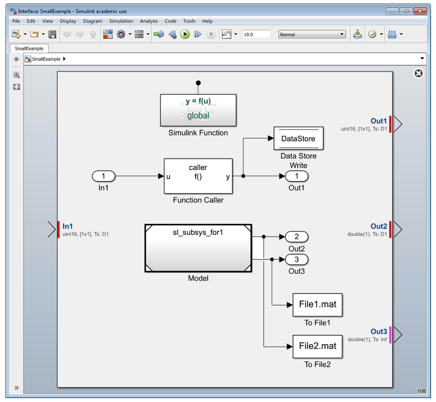
In this paper, we investigate modularity principles for Simulink as a widely-used tool for developing embedded control systems. The Simulink language is comprised of blocks representing different constructs, and each block has parameters that further specify it. Blocks are connected via signal lines representing the flow of data or control. Together, these elements form block diagrams known as models. Figure 2(a) shows an example model that computes the sum of positive integers using three methods. C is the most widely used programming language for embedded software aspencore20192019embedded, and in our experience most developers of Simulink models also work closely with C. We provide analogies for some Simulink constructs to the standard C language (C18) ieee2018information to better understand Simulink and to eventually draw comparisons between their design principles. Both C and Simulink are not object-oriented languages, enhancing the basis for comparison. Note, we do not discuss how a model is generated into C code, but rather position a model as the primary design artifact in Simulink, in the same way source files are in C. We are interested in the design-time view, rather than the compile-time view. Thus, a Simulink model (.mdl/.slx) is comparable to a C source file (.c). However, there is no notion of a header file (.h) and the interface that it provides. This is due to the top-level block diagram not providing sufficient information about the interface, as explained in Section 5.
(Virtual) Subsystems: In general, a subsystem is used to group blocks and introduces hierarchical layering. Although there are many kinds of subsystems, the most common is the virtual Subsystem.11 1 We refer to a virtual Subsystem simply as a Subsystem. It assists developers by only visually grouping together blocks. The Simulink engine expands virtual Subsystems in place before the execution of the model mathworks2019simulink, akin to a C preprocessor expanding a macro – but one time only. We do not elaborate on other nonvirtual (i.e., atomic) subsystems besides Simulink Functions, because they have additional semantics that are not useful for our purposes.
Libraries: A Library is a special kind of model. Blocks stored in a Library become reusable, as the Library stores the block prototype. Other models can then use an instance of the Library block. Any updates to the Library block will propagate into the models that use it. Instances of a Library block act as references to a library block and are updated/replaced pre-compile time. Conceptually, a library block is akin to a normal (multi-use) macro in C.
Data Flow: Data passing in a Simulink model is represented using signal lines. However, constructs such as Goto/From pairs and Data Store Memory Read/Write blocks enable implicit data passing, without a line. This is known as hidden data flow bender2015signature because data can cross certain block boundaries (e.g., Subsystems), without being immediately evident. Figure 2(a) shows a Data Store Write that passes data outside of the model. In C, variable names represent stored data, while in Simulink it is mapped out with (named or unnamed) signal lines. In C, there are ways we can store and move data that are difficult to follow; using pointers for instance. Similarly, Simulink has a variety of ways of storing and moving data that, if not used carefully, make it difficult to understand a model’s data flow. For that reason, it is important to define interfaces of modules to improve their understandability.
Workspaces and Data Dictionaries: Data and definitions that contribute to the specification of a model can exist outside the block diagram, in the Matlab (base) workspace, model workspace, and/or one or more data dictionaries (mathworks2019simulink, ch.62). The Matlab workspace stores temporary data. For permanent data storage, a model workspace is used to save data in a model file, or a data dictionary can store data in a separate .sldd file.Workspaces and data dictionaries are similar to a C module dedicated to storing/defining external variables.
Model References: A model can be directly referenced from another model using a Model Reference block. Unlike libraries, referenced models can be independently simulated. Like subsystems, each Model Reference adds hierarchy to the model (mathworks2019simulink, ch.8). Figure 2(a) shows a Model Reference to the model sl_subsys_for1, displayed in Figure 2(c). The use of a model reference is similar to the C preprocessing directive #include. A referenced model is modelled independently, and is code generated separately from the models that reference it. A model reference in some parent model will make available all exported Simulink functions (see Section 3) to that parent model, in a similar way that including a C header will give access to externally defined functions and variables.
Simulink Functions: A Simulink function is a grouping of reusable logic. It can be defined via a Simulink Function block,22 2 Introduced in R2014b. The Function Visibility parameter was added in R2017b. or in a Stateflow chart as a Simulink Function. As the Simulink Function block is the most general of these two, we focus on this kind, and leave the treatment of Stateflow Simulink Functions to future work. The scope of a Simulink Function, i.e., where it can be used, is determined by both its hierarchical placement in the model and its Function Visibility (FV) parameter. The FV parameter can be set to either scoped or global, but by default it is scoped mathworks2019simulink. The rules for determining the scope of a Simulink Function are not straightforward, and are described in detail in jaskolka2020comparison. They are summarized in Table 2 and briefly discussed below.
A Simulink Function with global FV can be placed anywhere in a model and will be available for external use in the model hierarchy.33 3 Models exporting functions must be configured as export-function models (mathworks2019simulink, ch.10). When a Simulink Function has scoped visibility, its placement in the model affects its accessibility. If placed at the root it is externally accessible in the model hierarchy. The difference between a global Simulink Function and a scoped Simulink Function at the root is in the way it is called. In the latter, the function name must be qualified with the Model Reference block name. If the scoped Simulink Function is placed in a virtual subsystem it is available in the parent subsystem and any descendants; otherwise if placed in a nonvirtual subsystem it is only available at that level.
| Case | Placement | Function
Visibility |
Scope |
|---|---|---|---|
| 1 | Don’t care | Global | External |
| 2 | Root | Scoped | External |
| 3 | Virtual Subsystem | Scoped | Internal |
| 4 | Nonvirtual Subsystem | Scoped | Internal to Subsystem |
The concept of a Simulink Function is analogous to a function in C, with some semantic differences. While C functions are external by default, Simulink Functions are scoped by default. In C, one can use functions from a different source by including the header file. To use a Simulink Function from a different model, that model must include a Model Reference and the function must have external scope. C static functions support modularity by restricting the scope of design details. In this case, the function’s name is invisible outside of the file in which it is declared, and is analogous to a local Simulink Function.
A summary of the comparison between C and Simulink constructs is shown in Table 3. Given this mapping, Simulink Functions can be used with other Simulink constructs to support modularity in a way that facilitates information hiding. This is described in the following sections.
| C | Simulink |
|---|---|
| Source file | Model |
| Header file | Not Available |
| Include | Model Reference |
| Function | “Global” Simulink Function (Case 1) |
| Member function | “Scoped” Simulink Function (Case 2) |
| Static function | “Local” Simulink Function (Case 3 & 4) |
| Macro (single-use) | Virtual Subsystem |
| Macro | Library |
| Variable | Data Store Memory |
| External data definitions | Workspace/Data Dictionary data |
4 A Simulink Module
A module is a component of a software system. It is a separate unit of a program that encapsulates closely related algorithms (e.g., functions, procedures) and data (e.g., data structures, variables) parnas1972criteria. Encapsulation means restricting access to a portion of the module, such that certain elements are not accessible outside of the module, but can be manipulated via public elements revealed on the module’s interface. In this section, the notion of a module in Simulink is introduced, drawing from the C analogy in Section 3.
Modular programming in C entails decomposing a system into separate modules srivastava2008modular; oualline1997practical. Each module consists of a source file that groups together definitions of related functionality and data, while a module’s interface is described by its header file. A module’s implementation should be considered private, or internal, to the module, and only those elements listed on the interface are accessible to other modules which import the interface. The ability to selectively hide or expose functions is achieved via the use of the static keyword, as shown in Figure 3, where the functions set and get are public, while the static function foo and static variable var1 are private. If another module wishes to use this module’s public elements, it can do so by including the module’s interface, and then making calls to public functions in the module, with parameter values from the calling program.
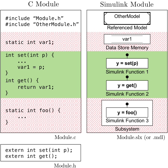
It is possible to employ the same modular approach in Simulink. Although there are several componentization techniques in Simulink, we wish to utilize the construct that best supports encapsulation, and thus information hiding. In previous work we found that a Simulink Function’s unique ability to be scoped enables one to effectively hide it from other parts of the model in which it resides, or other models (Table 1). Moreover, a Simulink Function helps to prevent some hidden data flow implicitly crossing over its boundary. Simulink Functions prove to be best suited to help us build modular Simulink designs that can actively support encapsulation and thus facilitate information hiding. The result of the comparison of Simulink componentization techniques (i.e., jaskolka2020comparison) leads to the proposed method for constructing modules in Simulink. Figure 3 illustrates how we can build Simulink modules based on the essential components of a module in C. The Simulink module uses: i) Model References to import other Simulink modules; ii) properly scoped Data Stores as state data private to the module; iii) Simulink Functions as functions exported by the module; and iv) Subsystems to restrict a Simulink Function so that it is private to the module. Like in C, the proposed Simulink modules are not object-oriented classes, and cannot be instantiated multiple times to create multiple objects. However, they make it possible to achieve information hiding in Simulink designs, so that the designs become more robust with respect to (foreseen) changes.
5 Simulink Module Interfaces
An interface is the set of services that each module provides to its clients ghezzi2002fundamentals. A syntactic interface is generally represented as a statement of elements and their properties that the module chooses to make known to a user or client modules. As shown in Figure 3, a Simulink module has no concept of an explicit interface like that provided in C. For this reason, we now define a Simulink module interface, so as to be able to extract it automatically from a Simulink module. A syntactic module interface contains:
-
inputs — data the client needs to provide
-
outputs — data the module promises to provide
-
exports — functionality the module provides to users
It is important that no unnecessary information is disclosed to the client on the interface. The client needs to know what the module agrees to provide via the interface, but does not need to understand the details of the implementation. As long as the interface remains the same, changes to the implementation can take place without affecting users in any way.
This interface is consistent with how many programming languages specify interfaces. Modern programming languages typically use keywords such as Definition or Public to delineate the “interface”, and Implementation or Private to separate out the private implementation. The interface usually consists of only those elements that are necessary to make use of the exported functionality (e.g., constant, type, variable, function prototype), but can also import elements that are needed in the interface itself. Note that it is usually possible to make module variables public, but in the spirit of information hiding, module variables (as opposed to “parameters”) should never be exposed on the interface.
The prevailing view is that a Simulink model’s interface is comprised of the Inports and Outports of the top-level system (e.g., doerr2017good; gerlitz2015detection). This is reflected in the Interface Display feature provided by Simulink, as shown in Figure 2(a). The Interface Display aims to provide users with a better view of the system’s interface (mathworks2019simulink, ch.12), and we can see that one Inport and three Outports are displayed around the edge of the model. However, a model’s interaction with other systems and its environment can consist of additional communication constructs that Interface Display fails to show—in this case a Data Store Write, two To File blocks, and an exported Simulink Function. Interface Display is thus insufficient in describing the actual interface of a model. Although this example is simple, the interface of a model can quickly become more difficult to understand due to the fact that these constructs can be placed anywhere in a model, potentially several layers deep. Thus, it can be difficult to “see” a Simulink module’s interface and to understand what the module is exposing to other modules. The notion of signature of a Simulink Subsystem can be used to represent the subsystem’s interface bender2015signature. It addresses the concerns with implicit data flow between subsystems by including in the subsystem’s signature both the explicit data flow mechanisms (i.e., Inport/Outport) and the implicit data flow mechanisms (scoped or global Goto/From blocks and Data Store Read/Write/Memory blocks). We build on this idea to define the module’s interface and represent it in the module in a similar way. This definition was then used to develop a design pattern in Simulink, as well as tool support to automatically extract and visualize it in a model.
5.1 Definition
A depiction of all the elements of a Simulink module’s interface is shown in Figure 4. Shared data is defined via Inport blocks, as well as others that are usually not considered, such as the From File and global Data Stores that are read. The interface also includes the module outputs via Outport blocks, as well as other blocks such as To Workspace and global Data Stores that are written to. Shared functions are Simulink Functions that are exported from a module. The lines (both solid and dashed) show all the possible data flow between a module and other workspaces. It is our recommendation to restrict the flow of data, as denoted by the dashed/crossed out items, however, this is discussed in Guideline 4 in Section 6.

with restricted items dashed/crossed out.
We can describe a Simulink module interface via standard set-theoretic definitions. These definitions not only help to make the interface precise, they also support the creation of tools. In particular, we use this definition to implement the interface extraction and representation in the Simulink Module Tool. We define a Simulink module simply as a set of blocks. We consider the block diagram (top-level) system itself to be a part of this set, so as to treat the system and subsystems the same. We abstract away the notion of signal flow between the blocks, as we are not concerned with intra-module communication (it was previously addressed bender2015signature), but rather the inter-module communication not represented by conventional signals.
Definition 1 (Identifiers I)
- •
is the set of all blocks in the module , i.e., those at the top-level as well as any that are contained within other blocks (regardless of hierarchy).
- •
is the set of all Subsystem blocks in the module , as well as the root system, so .
Definition 2 (Block Containment)
For some blocks and , denotes that is wholly contained in . It can also be said that is a child of the container .
Definition 3 (Parent Block)
The partial function is defined,
Definition 4 (Root Block)
The function , where , is defined,
A block is in the root system of module when its parent in turn does not have a parent, or, block has no defined grandparent.
Definition 5 (Identifiers II)
- •
is the set of all Inport blocks
-
represents root-level inports () and is defined,
-
- •
is the set of all Outport blocks
-
represents root-level outports () and is defined,
-
- •
is the set of all Simulink Function blocks
-
represents global functions ()
-
represents scoped functions ()
-
represents local functions () and is defined,
-
- •
TF(M) is the set of all To File blocks
- •
FF(M) is the set of all From File blocks
- •
FS(M) is the set of all From Spreadsheet blocks
- •
TW(M) is the set of all To Workspace blocks
- •
FW(M) is the set of all From Workspace blocks
- •
DS(M) is the set of all global data stores
-
DSR(M) represents global data stores that have a corresponding Data Store Read block
-
DSW(M) represents global data stores that have a corresponding Data Store Write block
-
Definition 6 (Inputs)
, the inputs of module , is a tuple (, , , , ) of root-level Inport, From File, From Spreadsheet, From Workspace, and global Data Store Read blocks, where , , , and .
Definition 7 (Outputs)
, the outputs of module , is a tuple (, , , ) of root-level Outport, To File, To Workspace, and global Data Store Write blocks, where , , , and .
Definition 8 (Exports)
, the exports of module , is the set of exported Simulink Function blocks, . Global Simulink Functions are included as they are always on the module interface. Scoped Simulink Functions are included if they are at root-level, i.e., they will be exported on the module interface.
Definition 9 (Interface)
, the interface of a module , is a tuple of inputs, outputs, and exports, .
5.2 Design Pattern
We can now create a design pattern within the model file to provide an easily understood view of the module’s interface based on Definition 9. The design pattern is placed in a Simulink module at the root, to the left of any other elements at that hierarchical level. It contains labelled sections corresponding to Definitions 6–8. Where possible, the interface design pattern is represented using commented out blocks, thus preventing it from having any behavioural impact on the module or adding new code during code generation. If instantiating the design pattern in the module is not possible, the interface can be represented in text form in the Matlab Command Window. In the textual description of the interface, each element’s full path name, data type, dimensions, and sample time are listed. The tool we developed, the Simulink Module Tool (Section 7), supports the automatic creation of an interface in both visual and textual forms. The visual interface for Figure 2(a), as generated by the tool, is shown in Figure 5(a), and has four elements that the MathWorks Interface Display does not show. This is a concrete application of the definition of a module interface as presented in Section 5.1.
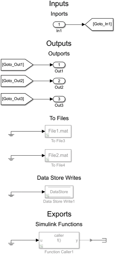
as generated by the Simulink Module Tool.
5.3 Benefits
There are several practical benefits and situations in a software engineering methodology where an interface in a Simulink module is beneficial. We describe these use cases in what follows.
Development
Passing information that is too detailed, unnecessary, arbitrary, or potentially changeable, violates software design principles. Clear interfaces help developers review them critically and examine whether their constituents are, for example, likely to change, too low-level, or unnecessary.
Collaboration
The presence of an interface is also invaluable in understanding a module for the first time, particularly when it originates from a different developer or source. If an interface is provided, the developer can use the module in a black-box fashion, without taking the time to understand the internals of the design.
Testing
With an easy to identify interface, all the module inputs and outputs are evident to a tester. When using a third-party testing tool such as Reactis by Reactive Systems, a developer can quickly identify module inputs/outputs that may not be included automatically by the tool. In such cases, a complete and visual interface flags them and allows the user to deal with them appropriately, resulting in better coverage bender2015signature.
Production
Several constructs that can be on a module interface are not recommended for a module that is to be used to generate production code (e.g., To File, From Workspace, etc.). However, these constructs are useful to developers during module development and simulation. An interface will capture such constructs, and empower developers to use them with the knowledge that they will be easy to identify and remove once a module is ready to be transitioned to production.
Documentation, Refactoring, and Maintenance
Documentation of Simulink models is often deficient schaap2018documenting; pantelic2019something. It can be difficult for developers to understand the overall functionality of complex models, as well as how they interact with other models. An interface makes this clear at the root level of the module, saving the developer from navigating to other levels. Structuring a module such that it always contains an up-to-date interface eases documentation efforts, and supports the concept of “self-documenting” software.
6 Modelling Guidelines
The use of Simulink Functions and a syntactic interface help create Simulink modules. Guidelines are useful for further supporting good practices when using these approaches. In this section, we discuss existing modelling guidelines for Simulink, and present new ones to address gaps where current guidelines fall short. The Simulink Module Tool provides automated compliance checking for these guidelines, and is discussed in Section 7. A user is able to select one or more of these guidelines, and any violating blocks will be reported. To the best of our knowledge, no other tools support these guidelines.
6.1 Simulink Functions
MathWorks is the de facto authority on best practices for designing with Simulink. Their advisory boards mathworks2012mathworks; mathworks2015japan provide the most influential guidelines, but currently, none address Simulink Function scoping. The Motor Industry Software Reliability Association (MISRA) Simulink guidelines also pre-date Simulink Functions misra2009misra. Recommendations on using Simulink Functions in order to promote best practices for supporting modularity and information hiding are introduced below. These guidelines are widely accepted in other languages to increase understandability, promote maintainability, and reduce errors, thus, we adapt them for Simulink R2014b and newer releases.
Guideline 1 (Simulink Function Placement) Place the Simulink Function block in the lowest common parent of its corresponding Function Caller blocks. Do not position the Simulink Function in the top layer for no reason. Avoid placing Simulink Function blocks below their corresponding Function Caller blocks.
Guideline 2 (Simulink Function Visibility) Limit the FV parameter of the Simulink Function block’s trigger port to scoped if possible.
In textual programming languages, it is good practice to ensure variables and functions are declared at the minimum scope from which their identifiers can still reference them martin2008clean. This promotes readability, reliability, and reusability of the code unicarnegiemellon2020sei. In Simulink, the same treatment is recommended for Data Store Memory blocks and Goto blocks, in order to support code comprehension, maintenance, as well as to avoid unintended access pantelic2018software; mathworks2012mathworks; misra2009misra. For these reasons, we introduce the two aforementioned guidelines for Simulink Function blocks.
Guideline 1 describes how to position Simulink Function blocks in order to minimize their accessibility both inside and outside the module. This is achieved by placing Simulink Function blocks as low as possible in the hierarchy, while still allowing any function calls to reference their corresponding Simulink Function block without added name qualifiers. The exception to this occurs when the intent is to associate a Simulink Function with its parent subsystem. This may be to increase the reusability of the subsystem itself, so the Simulink Function is encapsulated by that subsystem, even though Function Callers may be present above it in the hierarchy.
The hierarchical placement of a Simulink Function can also affect its presence on the module’s interface. If it is scoped and placed at the root, it will be externally accessible by other modules. A similar treatment for a Simulink Function’s FV parameter is recommended in Guideline 2. It should be set to its most restrictive setting if possible.
Guideline 3 (Simulink Function Shadowing) Do not place Simulink Functions with the same name and input/output arguments within each other’s scope.
Function overloading occurs when multiple definitions of a function exist with the same name but different input or output arguments. Simulink does not allow a Simulink Function to be placed in a Subsystem that already contains a Simulink Function with the same name. However, if the placement of a Simulink Function is at a different hierarchical level than another of the same name, one can define functions that shadow/mask each other. However, since scoping rules for Simulink Functions are complex, and users may be unaware of a naming collision, it is best to avoid situations where more than one function with the same name and arguments is accessible. The Japan MathWorks Automotive Advisory Board (JMAAB) guideline jc_0791 recommends a similar treatment for data stored in multiple workspaces mathworks2019simulinkb.
6.2 Interfaces
The Simulink User’s Guide discusses good practices for interface design, including Simulink subsystem interfaces mathworks2019simulink. The guidelines provide information about where model objects/data can be stored, but provide no real guidance on where they should be stored. Moreover, the use of constructs that contribute to hidden data flow into or out of the model is not addressed. The MathWorks Simulink Check provides guidelines for “high integrity systems modelling” for models that must comply with DO-178C/DO-331, ISO 26262, and other standards mathworks2019simulinkd. One guideline recommends that top-level Inport blocks must have data type, port dimensions, and sample time parameters populated. This is good practice in general and will assist in making the details of the interface data flow clear.
MAAB/JMAAB provide a single guideline regarding interfaces, recommending the enabling of strong-typing in Stateflow charts. This is not directly useful for examining the model’s top-level interface. MAAB/JMAAB also provides a guideline which lists prohibited Simulink blocks, including To File and To Workspace blocks in control models mathworks2012mathworks; mathworks2015japan. Similarly, the Embedded Coder User’s Guide describes which Simulink blocks support C code generation, and provides details on how certain blocks are treated during code generation (mathworks2019embedded, ch.2). In particular, the blocks described in our proposed definition of an interface are treated as follows.
- •
Supported: Inport/Outport, Data Store Read/Write, Model Reference, Library, Simulink Function, Function Caller
- •
Ignored: To Workspace/From Workspace
- •
Not recommended for production: To File/From File, From Spreadsheet
Although To File, From File, and From Spreadsheet blocks are not recommended for production, developers may use them during development because they are valuable for prototyping and logging purposes. Thus, To File, From File, and From Spreadsheet should be represented on the interface. When using these blocks for prototyping, an interface that highlights these constructs will help in identifying them so they can be removed once the design is finalized. This approach will help support the Embedded Coder guideline.
Guideline 4: (Use of the Base Workspace) Do not use the base workspace for storing, reading, or writing data that a module is dependant on. Instead, place data in either the model workspace, if it is used in a single module, or a data dictionary if it is shared across modules.
A likely change for a module that is used for code generation is that it will change workspaces, from being situated in the base workspace of the Simulink development environment, to being flashed onto the target embedded device. One can anticipate and prepare for this future change by creating a stable interface from the first stages of development. This not only minimizes the need for changes later on, but can also reduce dependencies. This is achieved by restricting the use of interface elements that are used for prototyping or do not support code generation. In particular, developers should avoid using the base workspace for storing, reading, or writing data (including types, signals, etc.).
To see Guideline 4 applied, Figure 4 has restricted items dashed/crossed out, such as the base workspace and associated constructs. As a result, the data flow has been simplified significantly, with the dashed lines showing data flow that is eliminated. Interestingly, MAAB explicitly prohibits the use of To File and To Workspace blocks, but recommendations for their counterparts, the From File and From Workspace blocks as well as the From Spreadsheet block, are not provided.
7 The Simulink Module Tool
We developed the Simulink Module Tool to assist with applying our approach for constructing Simulink modules as described in Section 4, generating the interface defined in Section 5, and checking compliance to the guidelines proposed in Section 6. It is open-source and available on the Matlab Central File Exchange.44 4 www.mathworks.com/matlabcentral/fileexchange/71952-simulink-module-tool The capabilities of the tool are as follows:
- •
The tool converts between the different kinds of scoping for Simulink Functions (Figure 6(a)), so the user does not have to be concerned with remembering the complex scoping rules regarding FV and placement.
- •
The tool assists users in calling Simulink Functions that are in scope, with their appropriate qualifiers (Figure 6(b)). Right-clicking in the model and then selecting Call Function… from the Context Menu displays a listbox showing Simulink Functions that can be called from that location. Making a selection from this list creates a Function Caller with its Prototype, Input argument specifications, and Output argument specifications parameters automatically populated. Note: Simulink does not populate these fields automatically.
- •
The syntactic interface (Section 5) for a Simulink module can be automatically generated. It can be represented visually in the model, or textually printed to the Command Window.
- •
Module dependencies, such as Model Reference, Library, and data dictionaries, can be detected by the tool, and summarized for the developer. This is useful for ensuring that the necessary definitions/files are available in order to compile and simulate.
- •
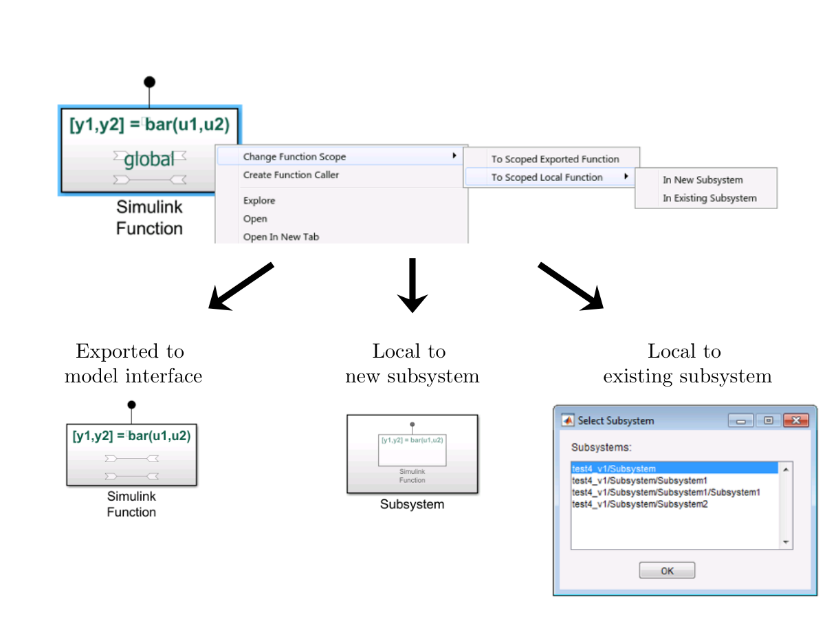
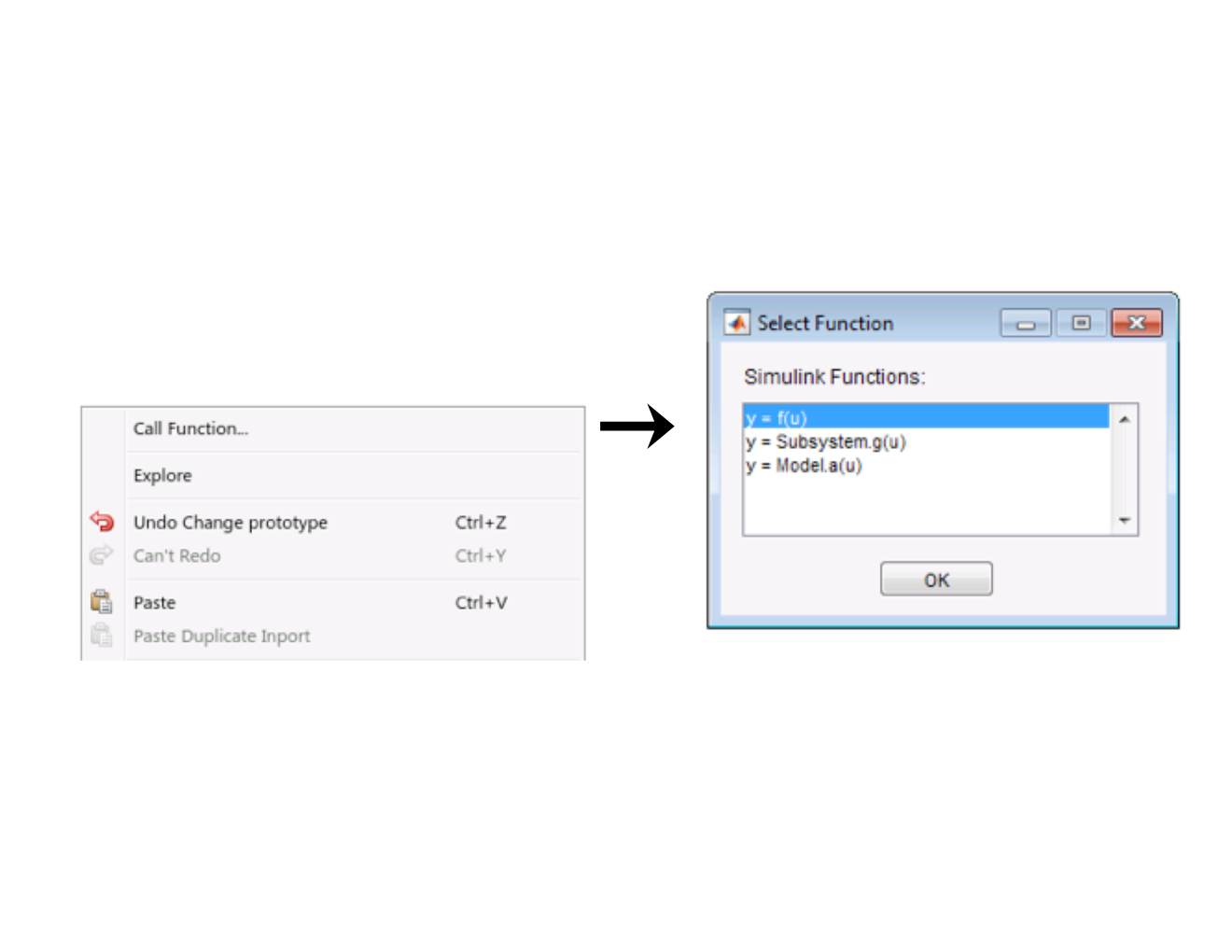
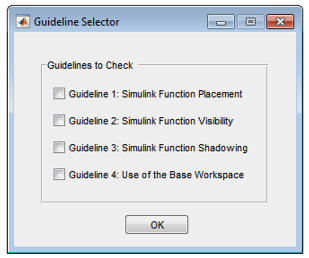
The goal of this tool is to make it easier to create Simulink modules in the first place, or to migrate existing models. An application of the tool is described in Section 8.
8 Nuclear Example
This section describes how our concepts were applied to restructure a Simulink implementation of a nuclear Shut Down System (SDS). The SDS system senses whether conditions in the reactor are no longer safe, and controls the lowering of control rods to stop (“shutdown”) the reaction. With 605 subsystems, 74/7 top-level inputs/outputs and 6036 total blocks, the model is too large to be presented here. However, it represents the size of small to medium sized designs found in practice.
Section 8.1 describes how the proposed module structure was applied in the SDS system. An explanation of how the Simulink Module Tool supports this process is provided in Section 8.2. Section 8.3 goes on to evaluate the approach’s effectiveness in terms of achieving a more modular system. The previously defined syntactic interface and guidelines are then applied to the example in Sections 8.4 and 8.5.
8.1 Application of the Simulink Module Structure
The first SDS implementation was implemented in Matlab R2012a by other developers some years before Simulink Functions were introduced in Simulink. It heavily makes use of linked blocks in its design, which link to various blocks in the SDS Library. The structure of the system is shown in Figure 7(a). The Power Estimation (PE) subsystem estimates the power of the reactor based on the average neutron over-power sensor values. It is one of the more complex components in the SDS. The PE implementation consists of several subsystems, which are defined in the SDS Library. PE contains secrets related to both hardware (e.g., which sensors are used), and software (e.g., how to accommodate for insufficient sensor readings). Unfortunately, a Library does not enforce information hiding jaskolka2020comparison. This is validated by the creation of a test model (Test.mdl in Figure 7) to probe the Library. Any of the blocks in the SDS Library can be used without restriction, and the internals of any subsystem are free to clients to use as well, even if this is not the developer’s intent. It is not possible to selectively expose or hide functionality, as it is with our approach.
By restructuring the PE subsystems into a Simulink module, we aim to hide implementation details from users of the PE module—the users should only be able to access the estimated power output value. This is an essential difference between defining modules as we recommend compared to using “coding” guidelines that are not enforced by the language (e.g., jaskolka2020comparison). Figure 7(b) shows the resulting module structure. A new model file (EstPower.mdl) was created and all related functionality was structured as a module as described in Section 4. This entailed organizing the operations as Simulink Function blocks, choosing which are to be external and which are hidden in the module, and scoping them based on our guidelines (Section 6). While there are many possible decompositions, the only exported function that is available for other modules to use is Estimated_Power. By placing it at the root level and setting the FV parameter to scoped, it can be called like a member function (i.e., EstPower.Estimated_Power (…)). The SDS model imports this function definition using a Model Reference to the module, and calls the function using a Function Caller block wherever the function is to be executed. Functionality in the SDS Library unrelated to PE, such as f_HTHPsentrip and f_NOPsentrip, remained as is.


Simulink Design Verifier (SDV) was used to formally prove that the designs before and after restructuring were behaviourally equivalent. A verification harness was created that references both designs. We then instrumented the verification model with proof objectives that state that each output of the original system must be equivalent to the corresponding output of the restructured system. SDV is then executed to formally prove the specified properties. For the SDS models, each property was successfully proven, thus verifying that the before/after systems are equivalent.
8.2 Using the Simulink Module Tool
The Simulink Module Tool facilitates the creation of Simulink modules, as we have done in the SDS example. The tool was used to make the changes described in Section 8, generate syntactic interfaces, and check guidelines. In particular:
- •
The tool converted between the different kinds of scoping for Simulink Functions when we were decomposing the PE functionality into Simulink Functions. The Simulink Functions were easily made internal to the module, while the f_EstPower_Output was appropriately scoped so that it was an exported Simulink Function and available to the SDS model.
- •
The tool assisted in calling the f_EstPower_Output Simulink Function, with its appropriate qualifier, from the SDS model. A Function Caller was automatically created with its Prototype, Input argument specifications, and Output argument specifications parameters pre-populated, saving time.
- •
- •
Module dependencies were detected and listed by the tool. This information was used in the evaluation when analyzing interface complexity and coupling.
- •
In summary, the Simulink Module Tool saved much time in constructing the new PE module, using the module’s external function, and analyzing the module’s interface, dependencies, and guideline compliance.
8.3 Evaluation
Through the use of our proposed Simulink module structure, we aim to achieve designs that are robust with respect to change. In order to perform an evaluation of the proposed module structure, we sought to objectively quantify the improvement to modularity and information hiding. This was done by evaluating characteristics that are widely considered effective indicators of design structure and modularity of large systems, such as coupling and cohesion. In addition, we evaluated the approach by evaluating potential impacts to the designs in terms of complexity, structural coverage, and performance.
8.3.1 Information Hiding
Although directly measuring information hiding has been attempted rising1994information, no metric has been widely accepted in either academia or industry. As a result, we use a qualitative analysis to reason about the effectiveness of our approach in supporting information hiding in the SDS system. The PE implementation contains secrets related to both hardware (e.g., which sensors are used), and software (e.g., how to accommodate for insufficient sensor readings). In the original design, knowledge of these secrets was easily leaked to the rest of the system, because the PE implementation internals were accessible from the SDS library without restriction. This was demonstrated through the use of a test model to probe the SDS library (Figure 7). Ultimately, the test model is able to access any of the elements in the library. For example, the f_AvePower function can be used by the test model without restriction, even though this should be a hidden module as it will expose the secret of how the average is computed. Moreover, users can also directly create links to any blocks that are internal to these top-level library blocks, further leaking internal design decisions. Restructuring the PE-related subsystems into a Simulink module allowed us to hide implementation details from users of the PE module. In the newly modified design, information hiding is enforced so that the user can access only the estimated power output value. With reference to Figs. 7(a) and 7(b), it is clear that the new module effectively hides the secrets that were previously accessible via Average_Power_Defaulted, f_AvePower, and Valid_ith_NOP_Signal_Indicator. In the restructured system, attempting to access any of these functions from the test model yields an error. This demonstrates that information hiding has improved.
8.3.2 Interface Complexity
The complexity of a system is often attributed to the interactions, or interfaces, between the system’s components. This complexity directly impacts the reusability, testability, and maintainability of the components. As discussed in Section 5, the interface of a Simulink model is generally considered to be comprised of Inport and Outport blocks, when in fact many other Simulink elements also contribute to the interface. This is also reflected in the tools currently available for interface complexity checking, such as Simulink Check Metrics Dashboard55 5 www.mathworks.com/help/slcheck/ug/collect-and-explore-metric-data-by-using-metrics-dashboard.html and Model Engineering Solutions (MES) M-XRAY.66 6 www.model-engineers.com/en/quality-tools/mxray/ As a result, we utilized the Simulink module interface definition in Section 5 to provide a complete syntactic description of a module’s interactions. The Simulink Module Tool automatically generates interface information, as well as dependency information, for a Simulink module (Section 8.2). Together this information provides an overall view of the many interactions that exist in a Simulink system. The interactions for the nuclear example are shown in Figure 8. Each Simulink model is represented with its interfaces and dependencies listed, while arrows represent the interactions. In Figure 8(a), the SDS model was heavily coupled with the SDS Library, with 344 links in its implementation to the 156 blocks exported from the Library. We restructured the PE functionality into its own module, and five of the SDS Library blocks were moved into this new module. We can see the SDS Library in Figure 8(a) is reduced from 156 blocks to 151 in Figure 8(b). Due to the PE module’s support for information hiding, only one of the blocks is actually exported by the module, and the remaining four are hidden and not available on the interface, causing a reduction of four fewer blocks on the interface. In total, these hidden blocks reduced the dependency of the SDS model on the Library by 31 links. However, a new Model Reference to include the interface of EstPower.mdl was introduced, as reflected in the Model Reference count in the SDS in Figure 8(b). Overall, the number of interactions in the system was reduced by 30, bringing down the total interface complexity.
8.3.3 Coupling and Cohesion
Coupling and cohesion are well known as indicators of the quality of a program decomposition, and are related to the concept of information hiding stevens1999structured. Coupling is a measure of the interconnections between modules, and increases as the complexity of the interfaces between modules increase stevens1999structured. While information hiding aims to hide the implementation details of a module, coupling measures how much another module is reliant on another module. Minimizing the coupling of a module makes it more robust with respect to changes because it reduces the connections by which changes and errors can propagate stevens1999structured. Thus, a good design that implements information hiding will also exhibit low coupling. Designs with low coupling and high cohesion lead to software that is more reliable and more maintainable fenton2014software. Cohesion is a measure of the relationships of the elements within a module, with the aim of ensuring that module elements are highly related to each other stevens1999structured. Cohesion also supports information hiding by ensuring that the contents of a module are strongly related to one secret. In the context of Simulink, coupling and cohesion are typically defined on a single Simulink model, based on the interactions of the contained blocks plaska2011simulink, or specifically Subsystem blocks gerlitz2016architectural; dajsuren2013simulink. There is a lack of system-level metrics for coupling and cohesion in the Simulink environment, and in turn, an absence of tools that automatically measure these qualities. Nevertheless, we manually analyzed the impact to coupling and cohesion that our approach had on the SDS.
The interconnections between the SDS Library and the SDS model as they were originally structured is shown in Figure 7(a) via the arrows that exist between the two. Although only a few of all of the connections are drawn in the figure, it is evident that the PE implementation in SDS.mdl was highly coupled with SDS_Library.mdl when compared with the restructured design in Figure 7(b). The second design reduced the interconnections to only one interconnection between SDS.mdl and EstPower.mdl. This reduction in coupling was additionally observed when comparing the syntactic interfaces of the models, as described in the previous section and shown in Figure 8.
In the original system, the SDS library contained all functionality related to the SDS. In the restructured system, those functions related to PE were decomposed into a separate module. This resulted in a more cohesive module of more closely related functions, in comparison to the original. Therefore, our approach positively impacted the design by reducing coupling and making the module more cohesive.
8.3.4 Cyclomatic Complexity
Cyclomatic complexity is the most widely-used metric in industry for gauging the structural complexity of software. Cyclomatic complexity measures the amount of decision logic in a program, or more specifically, the number of linearly independent execution paths through a program mccabe1976complexity. It has been shown to be indicative of the maintainability of software, which is our ultimate goal in supporting information hiding and modularity. MathWorks has adapted this metric for use directly on Simulink models, and is provided as an architecture metric via the Simulink Check toolbox. For more information on how MathWorks adapts this metric to Simulink models, please see the Simulink Check Reference mathworks2019simulink.
We leveraged Simulink Check to automatically compute cyclomatic complexity values for the nuclear SDS Simulink model. Table 4 shows the cyclomatic complexity results before and after the restructuring of the PE functionality into a Simulink module. The PE functionality originally had a cyclomatic complexity of 143. The SDS model decreased in cyclomatic complexity by 143. We expected this reduction in complexity as a result of moving the PE functionality out of SDS into its own module, but wanted to check that such a change did not inadvertently increase the complexity in SDS. Due to the application of our proposed module structure, the PE module itself had a substantial reduction in cyclomatic complexity by approximately 43%.
| Before | After | Difference | |
|---|---|---|---|
| SDS | 2413 | 2270 | -143 (6%) |
| EstPower | 143 | 81 | -62 (43.4%) |
The change in PE cyclomatic complexity is a result of our module structure leveraging Simulink Function blocks, whereas the original design relied heavily on Library blocks containing virtual Subsystems. In the PE functionality shown in Figure 7(a), the Valid_ith_NOP_Signal_Indicator Library block was used/linked 18 times. When the PE functionality was separated into a separate Simulink module, this block was converted to a Simulink Function block in order to hide its implementation according to our proposed Simulink module structure. In previous work, we performed a thorough comparison between componentization constructs, including Library and Simulink Function blocks jaskolka2020comparison. This analysis showed that when virtual (i.e., non-atomic) Subsystems are placed in a Library, each instance of the linked block is separate. Ultimately, a Subsystem in a Library will result in non-reusable code, that is, it will not be generated into a function. The original design contained 18 links to the Valid_ith_NOP_Signal_Indicator block, and each one added a cyclomatic complexity value of 4 per block (for a total of 72). Converting the linked Library block to a Simulink Function and then calling it 18 times reduced the cyclomatic complexity to a value of 4, as the Simulink Function provides one reusable definition of Valid_ith_NOP_Signal_Indicator, for a total cyclomatic complexity reduction of 68. However, the use of Simulink Functions can also increase the cyclomatic complexity when converting a virtual Subsystem to a Simulink Function. MathWorks has adapted the cyclomatic complexity metric to the Simulink language such that each atomic Subsystem adds a value of 1 to the complexity mathworks2019simulinkc. During the restructuring, 5 Simulink Functions replaced Subsystem blocks, and as a result, the cyclomatic complexity increased by 5. Moreover, the base cyclomatic complexity for a model with decision points is 1, so the new model also adds a value of 1 to the cyclomatic complexity of the PE module. Ultimately, the new structure and use of Simulink Functions resulted in the cyclomatic complexity being reduced by 68, and then increased by 6, for a net reduction of 62, as shown in Table 4.
In summary, although the use of Simulink Function blocks may come at a small cost to cyclomatic complexity, they produce more reusable designs while also supporting information hiding through their scoping ability. It is also important to note that Simulink Function blocks are a type of atomic subsystem, meaning that their contents are executed as a single unit. When converting from a virtual (or non-atomic) Subsystem, the execution order may be impacted. To remedy this, Simulink provides the ability to assign priorities to nonvirtual blocks to change their execution order according to the needs of the design (mathworks2019simulink, ch.37).
8.3.5 Testability
The SDV toolbox automatically generates test cases for Simulink models in order to maximize the structural coverage metrics of decision, condition, Modified Condition/Decision Coverage (MCDC), and execution coverage. SDV was run on each system for approximately 20 hours each, and the results are reported in Tables 5 and 6. There were 80 fewer total test objectives in the restructured system, as shown in Table 5. Overall, the number of processed objectives slightly increased. The number of satisfied objectives stayed relatively the same, while slightly more objectives were decided to be unsatisfiable by the prover. Also, the number of undecided objectives slightly decreased.
Table 6 reports no significant changes to structural coverage in the totals for the whole system. In measuring the structural coverage for the PE module alone, there was no change in the condition, MCDC, or execution coverage. However, a reduction of 10% in decision coverage was observed, for the same reasons outlined in Section 8.3.4. This change was primarily due to the Valid_ith_NOP_Signal_Indicator Library block being converted to a Simulink Function, making it one reusable function definition instead of 18 separate definitions. This eliminated 85 decision objectives, 68 of which were satisfied. The addition of the 5 Simulink Function blocks themselves increased the decision objectives by 5, all of which were satisfied, thus slightly increasing decision coverage. This was to be expected as the MathWork’s definition of decision coverage encompasses function call execution. However, the net decision coverage and decision objectives were decreased by 63 and 80, respectively, simply due to the elimination of function clones.
| Before | After | Relative Difference | |
|---|---|---|---|
| Total Objectives | 7099 | 7019 | 1.1% |
| Processed | 4427 (62.4%) | 4705 (67%) | +4.6% |
| Satisfied | 2899 (40.8%) | 2836 (40.4%) | 0.4% |
| Unsatisfiable | 1528 (21.5%) | 1869 (26.6%) | +5.1% |
| Undecided | 2672 (37.6%) | 2314 (33%) | 4.6% |
| Total | EstPower | |||||
|---|---|---|---|---|---|---|
| Before | After | Difference | Before | After | Difference | |
| Decision | 61% | 60% | 1% | 68% (111/163) | 58% (48/83) | 10% |
| Condition | 36% | 36% | 0% | 30% | 30% | 0% |
| MCDC | 15% | 15% | 0% | 4% | 4% | 0% |
| Execution | 99% | 99% | 0% | 100% | 100% | 0% |
8.3.6 Performance Comparison
As our approach relies heavily on the use of Simulink Function blocks, it is important to be cognizant of the potential for added overhead due to the increase in function calls and switching between modules in the new decomposition parnas1972criteria. To determine whether there was a change in efficiency between the original system and our modified system, they were simulated 200 times each. Our decomposition exhibited a minor increase in the execution times, as shown in Table 7. On average there was a penalty of 1.4%, but it is to be expected due to the introduction of function calls.
| Before (ms) | After (ms) | Difference | Percent Difference | |
|---|---|---|---|---|
| Mean | 5770 | 5848 | +78 | +1.4% |
| Best | 5719 | 5798 | +79 | +1.4% |
| Worst | 7811 | 8116 | +305 | +4.0% |
8.3.7 Summary of the Evaluation
Analyzing the modularity of a system entails measuring qualities such as cohesion, coupling, complexity, and others. In our evaluation, we looked at some of the best known indicators of modularity. We observed that the restructured system had an increase in information hiding, due to the appropriate scoping of design secrets. There was also a decrease in interface complexity, as the new decomposition hid previously exposed internal functions, thus removing them from the interface. This in turn resulted in a decrease in coupling, as the system interactions were reduced. An increase in cohesion was observed due to the grouping of PE-specific functionality. The cyclomatic complexity of the SDS decreased due to the decomposition of the system, and the PE module experienced a decrease in cyclomatic complexity due to the use of Simulink Functions for reusable functionality. In terms of structural coverage, although there was a minor reduction in the number of coverage objectives, there were no significant changes to coverage metrics. However, a slightly lower decision coverage in the PE module was exhibited due to Simulink Functions eliminating clones. As expected, there was a small performance penalty of 1.4% on average, due to Simulink Function overhead. In summary, the use of the proposed module concept for decomposing a Simulink model objectively exhibits improvements in key qualities that are indicative of modularity. The application of our proposed approach lead to more a modular design overall.
8.4 Using the Module Interface
In Section 8.3.2 the syntactic interfaces of the SDS and PE models were generated with the Simulink Module Tool. Figure 9 shows the generated interface representations from both the Simulink Module Tool and the MathWorks Interface Display for the PE module. The representation of the interface should show that a single Simulink Function is exported from PE, as also depicted in Figs. 7(b) and 8(b). In the interface generated by the Simulink Module Tool shown in Figure 9(a), we can see the Estimated_Power function under the “Exports” heading, to the left of the implementation. Unfortunately, the exported function is not shown in the MathWorks Interface Display view shown in Figure 9(b), because it only shows the Inport and Outports, of which there are none in this module. Our definition of an interface promotes a better, more complete, view of elements present on the interface, as demonstrated by the visible exported Simulink Function present in Figure 9(a), but missing from Figure 9(b). Although this is a simple example, it indicates that our definition of a Simulink module interface ultimately leads to a better understanding of the data flow into and out of the model.


8.5 Using the Guidelines
The new design adheres to the guidelines presented in Section 6, as follows. All functions were placed as low as possible in the module such that any corresponding Function Caller blocks in the SDS module can still access them (Guideline 1). This minimizes the scope of each of the Simulink Functions, and restricts their accessibility in the module to only where it is required. Only the Estimated_Power function is exported in order to make this functionality available on the PE interface, so that the SDS model can import it. All Simulink Function FV parameters are set to scoped, as global visibility is not needed in the system (Guideline 2). These guidelines helped to enforce information hiding in the system, and ensured the interfaces were as minimal as possible. Furthermore, each Simulink Function has a unique name, resulting in no shadowing (Guideline 3). This made the new decomposition of the PE module easy to understand. Lastly, the PE module’s functionality was already prepared as a production model, and did not contain any constructs that utilized the base workspace (Guideline 4). No further action was needed to support this guideline. The Simulink Module Tool was used to automatically validate that the PE module complied with these guidelines.
9 Conclusions and Future Work
Due to the increasing complexity of models, and their position as primary design artifacts maintained over many years, it is important to support modularity principles in Simulink. In other languages, modularity has been supported by following principles for ensuring modular decomposition, hiding implementation details, and separating the interface from implementation. To understand how to adapt these practices for MBD with Simulink, this paper presented a comparison of Simulink constructs to the constructs of the C language. Then, a novel approach for modular modelling was proposed and described. The approach entails structuring models as modules to support encapsulation and facilitate information hiding. The definition of a module interface was given, which effectively represents all data flow across the module boundary. Four new guidelines to encourage best practices were presented. The Simulink Module Tool was developed to automate the aforementioned contributions, and made available as an open-source contribution to the Matlab Central File Exchange. This paper also presented a proof of concept application of these ideas on an industrial system from the nuclear domain, which demonstrated the feasibility of the overall approach. We evaluated the approach and demonstrated that the restructured system increased in support for information hiding, simplified interfaces, decreased module coupling and increased cohesion, while not increasing the cyclomatic complexity of the system. Although decision coverage decreased, this was attributed to Simulink Function blocks replacing Library blocks that caused clones, which inflated the decision coverage objectives in the first place. Condition, MCDC, and execution coverage remained largely the same. A small performance penalty of 1.4% was incurred due to the use of Simulink Function blocks, but this is a small price to pay for the added modularity and ability to enforce information hiding in the system. In summary, this paper provided a new approach to structuring modular Simulink software systems.
As future work, we plan to extend this approach to the Stateflow environment, which is a subset of the Simulink language that uses functions in state machines and flow charts. A survey of likely changes in industrial models is underway. Different versions of industrial software from a version control system are being analyzed to create a taxonomy of likely changes for Simulink models. This will help in understanding how frequently occurring changes can be better accommodated in Simulink, as well as potentially identify other software engineering principles which can prove useful. A comprehensive review of other traditional software engineering principles that need to be better supported in Matlab Simulink is necessary, followed by further work towards addressing any identified gaps.
References
- (1) AspenCore: 2019 embedded markets study. https://www.embedded.com/wp-content/uploads/2019/11/EETimes_Embedded_2019_Embedded_Markets_Study.pdf (2019)
- (2) Bender, M., Laurin, K., Lawford, M., Pantelic, V., Korobkine, A., Ong, J., Mackenzie, B., Bialy, M., Postma, S.: Signature required: Making Simulink data flow and interfaces explicit. Science of Computer Programming 113, Part 1, 29–50 (2015). DOI 10.1016/j.scico.2015.07.005. Model Driven Development (Selected & extended papers from MODELSWARD 2014)
- (3) Bialy, M., Pantelic, V., Jaskolka, J., Schaap, A., Patcas, L., Lawford, M., Wassyng, A.: Software Engineering for Model-Based Development by Domain Experts, 1 edn., chap. 3, pp. 39–64. Elsevier, Cambridge, MA, USA (2016). DOI 10.1016/B978-0-12-803773-7.00003-6
- (4) Boström, P.: Contract-based verification of Simulink models. In: Formal Methods and Software Engineering, pp. 291–306. Springer Berlin Heidelberg (2011). DOI 10.1007/978-3-642-24559-6˙21
- (5) Boström, P., Morel, L., Waldén, M.: Stepwise development of Simulink models using the refinement calculus framework. In: C.B. Jones, Z. Liu, J. Woodcock (eds.) Theoretical Aspects of Computing – ICTAC 2007, pp. 79–93. Springer Berlin Heidelberg (2007). DOI 10.1007/978-3-540-75292-9˙6
- (6) Carnegie Mellon University: SEI CERT C coding standard (2020). URL https://wiki.sei.cmu.edu/confluence/display/c/SEI+CERT+C+Coding+Standard
- (7) Dajsuren, Y., van den Brand, M.G.J., Serebrenik, A., Roubtsov, S.: Simulink models are also software: Modularity assessment. In: Proceedings of the 9th international ACM Sigsoft Conference on Quality of Software Architectures (QoSA), pp. 99–106. ACM, Vancouver, Canada (2013). DOI 10.1145/2465478.2465482
- (8) Dörr, H.: Good interfaces in large models (2017). URL www.model-engineers.com/files/content/MGIGroup/20170307_MGIGroup_Good_Interfaces_in_Large_Models.pdf. Modeling Guidelines Interest Group (MGIGroup) [Online; accessed Dec 2018]
- (9) Fenton, N.E., Bieman, J.: Software Metrics: A Rigorous and Practical Approach, 3 edn. CRC Press (2014)
- (10) Gerlitz, T., Kowalewski, S.: Architectural analysis of MATLAB/Simulink models with artshop. In: Proceedings of the 2016 13th Working IEEE/IFIP Conference on Software Architecture (WICSA), pp. 307–310. IEEE (2016)
- (11) Gerlitz, T., Tran, Q.M., Dziobek, C.: Detection and handling of model smells for MATLAB/Simulink models. In: International Workshop on Modelling in Automotive Software Engineering (MASE), vol. 1487, pp. 13–22. CEUR, Ottawa, Canada (2015)
- (12) Ghezzi, C., Jazayeri, M., Mandrioli, D.: Fundamentals of Software Engineering, 2 edn. Prentice-Hall, Upper Saddle River, NJ, USA (2002)
- (13) IEEE: Information technology – programming languages – C. ISO/IEC 9899: 2018 (2018). URL www.iso.org/standard/74528.html
- (14) Iwu, F., Galloway, A., Toyn, I., McDermid, J.: Practical formal specification for embedded control systems. IFAC Proceedings Volumes 37(4), 165–170 (2004). DOI 10.1016/s1474-6670(17)36113-x
- (15) Jaskolka, M., Pantelic, V., Lawford, M., Wassyng, A.: A comparison of componentization constructs in Simulink. In: WCX SAE World Congress Experience, 2020-01-1290, pp. 1–16. SAE International (2020). DOI 10.4271/2020-01-1290
- (16) Martin, R.C.: Clean Code: A Handbook of Agile Software Craftsmanship, 1 edn. Prentice Hall (2008)
- (17) McCabe, T.J.: A complexity measure. IEEE Transactions on Software Engineering SE-2(4), 308–320 (1976). DOI 10.1109/TSE.1976.233837
- (18) Molotnikov, Z., Schorp, K., Aravantinos, V., Schätz, B.: Future programming paradigms in the automotive industry. FAT-Schriftenreihe 287, 108 (2016)
- (19) Olszewska, M.: Simulink-specific design quality metrics. TUCS Technical Report 1002, Åbo Akademi University, Turku, Finland (2011)
- (20) Oualline, S.: Practical C Programming, 3 edn. Nutshell Handbooks. O’Reilly Media, Sebastopol, CA, USA (1997)
- (21) Pantelic, V., Postma, S., Lawford, M., Jaskolka, M., Mackenzie, B., Korobkine, A., Bender, M., Ong, J., Marks, G., Wassyng, A.: Software engineering practices and Simulink: bridging the gap. International Journal on Software Tools for Technology Transfer 20(1), 95–117 (2018). DOI 10.1007/s10009-017-0450-9
- (22) Pantelic, V., Schaap, A., Wassyng, A., Bandur, V., Lawford, M.: Something is rotten in the state of documenting Simulink models. In: Proceedings of the 7th International Conference on Model-Driven Engineering and Software Development, MODELSWARD 2019, vol. 1, pp. 503–510. INSTICC, SciTePress (2019). DOI 10.5220/0007586005030510
- (23) Parnas, D.L.: On the criteria to be used in decomposing systems into modules. Communications of the ACM 15(12), 1053–1058 (1972). DOI 10.1145/361598.361623
- (24) Parnas, D.L., Clements, P.C., Weiss, D.M.: The modular structure of complex systems. IEEE Transactions on Software Engineering SE-11(3), 259–266 (1985). DOI 10.1109/TSE.1985.232209
- (25) Rau, A.: On model-based development: A pattern for strong interfaces in SIMULINK. Gesellschaft für Informatik, FG 2(1), 12 (2002)
- (26) Rising, L.S., Calliss, F.W.: An information-hiding metric. Journal of Systems and Software 26(3), 211–220 (1994). DOI 10.1016/0164-1212(94)90012-4
- (27) Schaap, A., Marks, G., Pantelic, V., Lawford, M., Selim, G., Wassyng, A., Patcas, L.: Documenting Simulink designs of embedded systems. In: Proceedings of the 21st ACM/IEEE International Conference on Model Driven Engineering Languages and Systems (MODELS): Companion Proceedings, pp. 47–51. ACM, Copenhagen, Denmark (2018). DOI 10.1145/3270112.3270115
- (28) Srivastava, S., Hicks, M., Foster, J.S., Jenkins, P.: Modular information hiding and type-safe linking for C. IEEE Transactions on Software Engineering 34(3), 357–376 (2008). DOI 10.1109/tse.2008.25
- (29) Stevens, W.P., Myers, G.J., Constantine, L.L.: Structured design. IBM Systems Journal 38(2.3), 231–256 (1999). DOI 10.1147/sj.382.0231
- (30) The MathWorks: Mathworks automotive advisory board (MAAB): Control algorithm modeling guidelines using MATLAB, Simulink, and Stateflow (2012). URL www.mathworks.com/solutions/automotive/standards/maab.html. Version 3.0
- (31) The MathWorks: Japan Mathworks Automotive Advisory Board (JMAAB): Control algorithm modeling guidelines using MATLAB, Simulink, and Stateflow (2015). URL www.mathworks.com/solutions/automotive/standards/maab.html. Version 4.01
- (32) The MathWorks: Embedded Coder user’s guide (2019). URL www.mathworks.com/help/releases/R2019b/pdf_doc/ecoder/ecoder_ug.pdf. Version R2019b
- (33) The MathWorks: Simulink Check reference. www.mathworks.com/help/releases/R2019b/pdf_doc/slcheck/slcheck_ref.pdf (2019). Version R2019b
- (34) The MathWorks: Simulink Check user’s guide (2019). URL www.mathworks.com/help/releases/R2019b/pdf_doc/slcheck/slcheck_ug.pdf. Version R2019b
- (35) The MathWorks: Simulink modeling guidelines for high-integrity systems. www.mathworks.com/help/releases/R2019b/pdf_doc/simulink/hi_guidelines.pdf. (2019). Version 2019b
- (36) The MathWorks: Simulink user’s guide. www.mathworks.com/help/releases/R2019b/pdf_doc/simulink/sl_using.pdf (2019). Version R2019b
- (37) The Motor Industry Software Reliability Association: MISRA AC SLSF modelling design and style guidelines for the application of Simulink and Stateflow (2009). Version 1.0
- (38) Whalen, M.W., Murugesan, A., Rayadurgam, S., Heimdahl, M.P.E.: Structuring Simulink models for verification and reuse. In: Proceedings of the 6th International Workshop on Modeling in Software Engineering (MiSE), pp. 19–24. ACM, Hyderabad, India (2014). DOI 10.1145/2593770.2593776