Noncollinear antiferromagnetic order in the buckled honeycomb lattice of magnetoelectric Co4Ta2O9 determined by single-crystal neutron diffraction
Abstract
Co4Ta2O9 exhibits a three-dimensional magnetic lattice based on the buckled honeycomb motif. It shows unusual magnetoelectric effects, including the sign change and non-linearity. These effects cannot be understood without the detailed knowledge of the magnetic structure. Herein, we report neutron diffraction and direction-dependent magnetic susceptibility measurements on Co4Ta2O9 single crystals. Below 20.3 K, we find a long-range antiferromagnetic order in the alternating buckled and flat honeycomb layers of Co2+ ions stacked along the axis. Within experimental accuracy, the magnetic moments lie in the plane. They form a canted antiferromagnetic structure with a tilt angle of 14∘ at 15 K in the buckled layers, while the magnetic moments in each flat layer are collinear. This is directly evidenced by a finite (0, 0, 3) magnetic Bragg peak intensity, which would be absent in the collinear magnetic order. The magnetic space group is . It is different from the previously reported group, also found in the isostructural Co4Nb2O9. The revised magnetic structure successfully explains the major features of the magnetoelectric tensor of Co4Ta2O9 within the framework of the spin-flop model.
I introduction
Controlling magnetic order with an electric field, and electric polarization with a magnetic field are of both technological and fundamental significance. Energy-efficient devices of new types could be developed, for example, using the cross-coupling between the electric and magnetic orders in magnetoelectric (ME) and multiferroic compounds [1]. The research of the ME effects was initiated by the theoretical proposal [2] that the cross-coupling terms between the electric and the magnetic fields in the free energy are allowed in the compounds exhibiting certain structural and magnetic symmetries. The first compound exhibiting the ME effect, Cr2O3, was discovered shortly thereafter [3]. Since then, significant efforts were devoted to the search of new ME compounds, especially of those with a strong ME coupling as relevant to technological applications. This search is hindered by the rather restrictive requirements on the symmetries for the candidate materials [1]. However, even when such requirements are met, a physical mechanism producing the strong ME coupling must be present in the system. As a result, the number of compounds showing the strong ME effect is still quite limited.
Cr2O3 crystallizes in the corundum structure. It displays a rather strong and linear ME effect, which are both desirable properties. Compounds possessing similar structures, combined with the increased spin-lattice coupling, may therefore be considered promising ME candidates. The 42O9 ( = Mn, Fe, Co, and = Nb, Ta) [4] compounds are based on the corundum structure, and contain magnetic ions such as Co2+ and Fe2+ expected to have significant orbital magnetic moments conducive to increased spin-lattice coupling. In addition, they contain heavy nonmagnetic elements (Nb, Ta) with strong on-site spin-orbit interaction, which may facilitate the ME coupling indirectly. Recently, several members of this family have indeed been shown to exhibit complicated ME and multiferroic properties [5, 6, 9, 8, 10, 11, 7].

The structure of the 42O9 compounds is derived from the well-known corundum crystal structure of Cr2O3 in which four Cr sites are occupied by the magnetic ions, and another two sites by the nonmagnetic ions. This structure is illustrated in Fig. 1 using Co4Ta2O9 as an example [7]. The space group is trigonal (No. 165) [12]. There are two crystallographically distinct sites occupied by the Co2+ ions, both in the 4 Wyckoff position (1/3, 2/3, ): Co1 at 0.192, and Co2 at 0.986 [7]. Co1 forms the buckled honeycomb network shown in Fig. 1(b) [denoted as the buckled layer in this paper], while Co2 makes a rather flat honeycomb layer shown in Fig. 1(c), which we call flat for simplicity. These layers are stacked along the axis, forming a three-dimensional structure.
The ME properties of Co4Nb2O9 have been studied most extensively so far. It shows a significant linear ME effect in the magnetically ordered state [5], arguably influenced [5, 13, 14] by the unquenched orbital moment of Co2+. The direction of the induced electric polarization can be switched by rotating the magnetic field in the honeycomb plane [6] in the manner consistent with the trigonal symmetry of the system [15]. Magnetic order is key for understanding the ME effect. However, the magnetic structure of Co4Nb2O9 has been a subject of certain controversy [5, 16, 17]. Specifically, it is not agreed whether the magnetic moments are collinear [5] or tilted [16, 17] within the buckled honeycomb planes, as well as whether any axis moment components are present [5] or absent [16, 17]. Some of the large components of the ME tensor in Co4Nb2O9 have been accounted for by the spin-flop model in Ref. 5. However, this model does not explain all the tensor components observed experimentally. An alternative scenario has been proposed in a more recent neutron diffraction study in an applied magnetic field [17]. No spin flop was found in these experiments, and the observed ME effects were proposed to be associated with the field-dependent magnetic domain populations combined with tilting moments within the domains, at least in moderate applied fields (below 4 T). It is clear that detailed knowledge of the magnetic structure, as well as understanding of the magnetic domain population factors and their effects are needed to explain the complex magnetoelectricity of Co4Nb2O9.
Recently, intricate ME response has been reported in the magnetically ordered state of Co4Ta2O9 [7]. In contrast to the isostructural Co4Nb2O9, this response is strongly nonlinear. Also, for some directions of the applied magnetic field, the induced electric polarization changes its sign with the increasing field. This is somewhat puzzling because the only major difference between Co4Ta2O9 and Co4Nb2O9 is in the non-magnetic ions, Ta5+ and Nb5+, respectively. The origin of the distinct ME effects in these two compounds, therefore, deserves a detailed investigation. The magnetic structure of Co4Ta2O9 has been recently studied by neutron powder diffraction [12]. An -plane noncollinear magnetic structure similar to the one determined in Refs. 16, 17 for Co4Nb2O9, as well as the same magnetic space group, , were reported. Given the current controversial results on the magnetic structure of Co4Nb2O9, the key role of the magnetic order in the ME effect, and the apparent failure of the current models to explain this effect in Co4Nb2O9, it is essential to determine the magnetic structure of Co4Ta2O9 confidently. We also note that conflicting reports exist for the magnetic structure of the isostructural Fe4Nb2O9 [18, 19], which further emphasizes the difficulty of the magnetic structure problem in the 42O9 compound series. Single-crystal neutron diffraction studies, supported by other relevant measurements, are essential to address this problem.
In this paper, we determine the magnetic structure of Co4Ta2O9 using single-crystal neutron diffraction complemented by direction-dependent magnetic susceptibility measurements. Some characteristic features of the magnetic structure of Co4Ta2O9 found in our study, such as the -plane magnetic moments and the canted (collinear) antiferromagnetic order in the buckled (flat) honeycomb layers, are similar to those reported in the previous work on Co4Ta2O9 [12] and the isostructural Co4Nb2O9 [16, 17]. However, we find a distinct magnetic space group, , as opposed to reported in these references. The major difference is the direction of the refined magnetic moments. Symmetry analysis of the newly-determined magnetic order of Co4Ta2O9 accounts for the observed ME tensor [7] in the framework of the spin-flop model [5], giving a better agreement with the experimental data than the previously-reported magnetic space group. While the neutron diffraction results do favor the over the magnetic space group, the difference in the reliability factor is small. The direction-dependent magnetic susceptibility data were crucial for the confirmation of the magnetic space group in Co4Ta2O9. Our results emphasize the importance of the careful choice of the complementary measurements for the determination of the correct magnetic structure of the 42O9 compounds.
This paper is organized as follows. Section II describes the experimental details. Magnetic susceptibility and neutron diffraction results are given in Section III and Section IV, respectively. Implications of these results are discussed in Section V, and conclusions are given in Section VI. Appendix A and Appendix B provide details of the analysis of the magnetic susceptibility and neutron diffraction data, respectively. The symmetries of the and the magnetic space groups and the corresponding magnetic structures are discussed in Appendix C, and the magnetic structure factors of the (0, 0, L) magnetic Bragg peaks are given in Appendix D.

II Experimental Details
Two sets of Co4Ta2O9 single crystals were used in this work. One set was grown using the flux method, as described in Ref. 7. We refer to them as the flux crystals. The other set was produced using the traveling solvent floating zone method, the TSFZ crystals. The polycrystalline powder of Co4Ta2O9 was obtained by a solid-state reaction technique from the stoichiometric mixture of Co3O4 (99.99%) and Ta2O5 (99.99%) powders sintered at 1200 ∘C for 10 hours in air. It was used to make the feed and seed rods for the TSFZ growth.
Magnetic susceptibility measurements were done with SQUID magnetometry, using either a normal DC accessory or a reciprocating sample measurement system to increase the signal to noise ratio. Susceptibility measurements between 30 K and the base temperature (typically 2 or 3 K) were done in 0.1 T applied magnetic field. Measurements at higher temperatures were also taken. Zero-field-cooled (ZFC) and field-cooled (FC) measurements were done when necessary. Crystallographic axes were pre-determined by Laue x-ray diffraction, and cross-checked by a fixed-wavelength single-crystal x-ray diffraction (a Mo source).
Neutron diffraction experiments were performed at the Single Crystal Diffractometer (SXD) beamline at ISIS, where the time-of-flight Laue technique is used to access large 3-D volumes of reciprocal space in a single measurement. Single crystals were screened by magnetic susceptibility, x-ray diffraction, followed by further quality checks with neutron Laue diffraction at room-temperature on SXD. One crystal from each growth method was selected for the neutron diffraction measurements. The 22-mg flux crystal was of a spherical shape, about 2 mm in diameter. The data were collected at three identical rotation angles, in the paramagnetic state at 25 K for 18 hrs, and in the magnetically ordered state at 15 K for 42 hrs. The 1.28-g TSFZ crystal was of a cylindrical shape, 6 mm in diameter, cut from a bigger rod. For this crystal, the data were collected at six identical rotation angles at 25 and 15 K for 41.2 and 68.7 hrs, respectively.

III Magnetic susceptibility
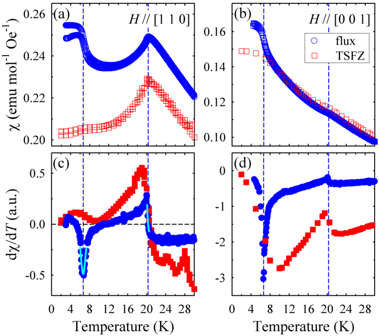
We performed direction-dependent magnetic susceptibility measurements on Co4Ta2O9 using both the flux and TSFZ crystals. The major features are shown in Fig. 2. The in-plane susceptibility with the magnetic field along the [1 1 0] direction is depicted in Fig. 2(a), and the -axis susceptibility (field parallel to [0 0 1]) is shown in Fig. 2(b). Figs. 2(c, d) show the corresponding derivatives with respect to temperature for the ZFC data. The transition temperature for the antiferromagnetic order TN, defined from the sharp cusp of in the in-plane data, is 20.3 K in the both samples. The anomaly at the TN is much less pronounced in the -axis data. This means that magnetic moments are dominantly confined in the plane.
There is an additional anomaly at a lower temperature, at which a bifurcation between the FC and ZFC data is observed. As determined by the minimum in the temperature derivative, it occurs at 6.65 K in the flux crystal. While less pronounced, this anomaly is also present in the TSFZ crystal at a slightly higher temperature. The observed temperature hysteresis and the sample dependence indicate a complex nature of the magnetic state at the lowest temperatures, where magnetic domain or glassy effects could play a role. In this work, the Co4Ta2O9 magnetic structure was determined at 15 K, safely outside of this complex regime. Detailed studies of the magnetism below 6.65 K would be desirable, but are beyond the scope of this paper.
To characterize the in-plane magnetic anisotropy, we made magnetic susceptibility measurements for a large number of representative high-symmetry directions in the trigonal plane. A flux crystal of a hexagonal shape with well-defined facets was used. The crystallographic axes were confirmed by x-ray Laue measurements. Fig. 3 shows the data for five such directions, averaged for several repetitive measurements as discussed in detail in Appendix A. Below TN, the largest and the lowest susceptibilities are found for the magnetic field along the [1 -1 0] and the [1 1 0] trigonal directions, respectively. For the other directions, the data interpolate between these values. These measurements clearly demonstrate that the magnetic moments point predominantly along the [1 1 0] direction, assuming a (nearly) collinear antiferromagnetic structure and a dominant single magnetic domain state (to be discussed in detail later). By convention, this means that the magnetic easy axis is [1 1 0], while the hard axis is [1 -1 0]. These results will play an important role in the analysis of the neutron diffraction data discussed in the next Section.
| Magnetic model | (No. 15.88) | (No. 15.87) | |||
|---|---|---|---|---|---|
| Robs | (Co1) / (Co2) | Robs | (Co1) / (Co2) | ||
| Flux | Collinear, Mc=0 | 5.94 % | 2.40 / 1.34 | 6.15 % | 1.64 / 1.64 |
| Collinear, Mc0 | 5.97 % | 2.34 / 1.36 ∗ | 6.15 % | 1.65 / 1.69 | |
| Noncollinear, Mc=0 | 6.31 % | 1.89 / 1.89 | 5.92 % | 2.02 / 1.44 † | |
| Noncollinear, Mc0 | 6.06 % | 2.11 / 1.63 ∗ | 5.91 % | 2.02 / 1.45 | |
| TSFZ | Collinear, Mc=0 | 10.43 % | 2.82 / 1.84 | 10.71 % | 2.20 / 2.20 |
| Collinear, Mc0 | 10.31 % | 2.82 / 1.84 | 10.26 % | 2.20 / 2.78 ∗ | |
| Noncollinear, Mc=0 | 10.53 % | 2.35 / 2.35 | 10.34 % | 2.74 / 2.04 † | |
| Noncollinear, Mc0 | 10.27 % | 2.52 / 2.17 ∗ | 10.03 % | 2.64 / 2.60 ∗ | |
IV Neutron diffraction
To determine the magnetic structure of Co4Ta2O9, neutron diffraction measurements were performed using the both types of single crystals. The same flux sample, and TSFZ sample from the same growth were used for the neutron diffraction and the magnetic susceptibility measurements shown in Fig. 2. In this paper, we determine the magnetic structure at T = 15 K, well above the magnetic transition to the complex phase at 6.65 K. The results of the neutron diffraction data analysis are shown in Fig. 4. Panels (a-c) and (d-f) present the calculated versus the observed structure factors for the flux and the TSFZ crystal, respectively.
The nuclear structure in the paramagnetic state was refined first, using the whole data set collected at 25 K. Figs. 4(a, d) show the results of this refinement for the set of the lower- Bragg peaks, as relevant to the magnetic refinements described below. The crystal structure nearly identical to the one determined at room temperature by x-rays [7] was found, in the same trigonal space group. When this fixed nuclear structure is used for the data taken in the magnetically ordered state at 15 K, additional unaccounted diffraction signal is clearly visible for a set of the experimental Bragg peaks. That is, Fobs is larger than Fcalc for these peaks. They are easily seen below the Fobs = Fcalc line in Figs. 4(b, e). Importantly, this additional intensity is only prominent for the reflections with lower wave vectors . This indicates the magnetic origin of the extra intensity for these peaks. In Fig. 4, the same set of Bragg peaks is shown in every panel. A thorough search for any additional Bragg peaks covering both the commensurate and incommensurate positions in the reciprocal space was carried out in the magnetically ordered phase using our area detector data. Only a very small number of new Bragg peaks was found (to be discussed later). They were all indexed using the integer (H, K, L) positions in the parent crystal structure. This shows that the magnetic and the nuclear structure have the same unit cell, in agreement with the previously published neutron diffraction work [12]. Consequently, the magnetic ordering wave vector is = (0, 0, 0). The set of the observed peaks shown in Fig. 4, with 6.28 Å-1 as appropriate for the magnetic structure determination, was used in the magnetic refinements. The nuclear structure was fixed. The most reliable results, obtained as discussed below, are shown in Figs. 4(c, f). The addition of the magnetic structure to the refinements resulted in the obviously better fits. This is reflected by the reduction of the reliability factor Robs by 2.48 % and 5.18 % for the flux and the TSFZ sample, respectively. The full details of the refinement procedure can be found in Appendix B.
To find the magnetic space group candidates, group symmetry analysis [20] was applied to the parent nuclear space group (No. 165) with = (0, 0, 0). All the trigonal subgroups were inconsistent with the magnetic susceptibility data because they disallowed magnetic moments in the plane. The next available highest-symmetry choice is monoclinic. We found two candidates that were compatible with the predominantly in-plane magnetic moments, and that resulted in good fits to the neutron diffraction data collected at 15 K. These were (No. 15.88) and (No. 15.87). One of them, , was previously proposed for both Co4Nb2O9 [5, 16, 17] and Co4Ta2O9 [12]. Both these groups allow collinear and noncollinear antiferromagnetic order in the plane, as well as an antiferromagnetic -axis component. We have carried out refinements of the magnetic structure, starting with the simplest possible model, the collinear in-plane antiferromagnetic structure with no axis components. More complex models, allowing noncollinear in-plane structures, as well as the out-of-plane moment, were then considered. When the symmetry is lowered from the trigonal to monoclinic at the magnetic transition, three types of the in-plane magnetic domains are possible, distinguished by the three possible directions of the unique axis in the monoclinic cell. We found that the refinements using a single-domain model for the flux crystal worked well, while the model using three equally populated domains was necessary for the TSFZ crystal. The multi-domain model was also tested for the flux crystal data. It showed a similarly good fit with only a marginal improvement. Thus, we conclude that the larger TSFZ crystal contains all the possible magnetic domains with similar populations, while the smaller flux crystal probably exhibits a predominant single-domain state.

The refinement results are summarized in Table 1. The fits are characterized by the standard reliability factor Robs. Lower values of Robs signify a better model fit to the data. The difference in the average Robs for the flux and the TSFZ crystal may result from both the better crystallographic quality, and the smaller number of the observed Bragg peaks for the flux crystal. The main observation from the analysis given in Table 1 is the very small variation of the Robs values for all the models considered for a given crystal. Thus, it appears impossible to determine reliably the actual magnetic structure based on the fit quality alone. This could be the major reason for the difficulty of determining the magnetic structure of the 42O9 compounds described in the Introduction. Thus, specific signatures of the magnetic order type should be sought in the diffraction data, and in their absence, complementary experimental techniques should be exploited.
Firstly, in Table 1, we can exclude all the models with the collinear in-plane structures because new Bragg peaks of the (0, 0, odd) type appear below TN at small scattering wave vectors (signifying the magnetic origin of these chemically-forbidden peaks). As an example, the temperature dependence of the (0, 0, 3) peak is shown in Fig. 5. The intensity of these peaks is zero both in the parent space group, and for any type of the collinear in-plane magnetic order in and , with or without the axis magnetic moment. They acquire intensity as the moments start tilting in the plane, away from the collinear antiferromagnetic alignment. A detailed discussion of the magnetic structure factor of the (0, 0, L) peaks can be found in Appendix D. Secondly, most of the models involving nonzero out-of-plane moment (Mc) produced unrealistically large Mc values, which is incompatible with the magnetic susceptibility results. These models are marked with asterisk symbols in Table 1. The only noncollinear in-plane structure that converged well with reasonable components Mc is the model for the flux crystal. It gives Mc 0.2 , corresponding to the 6∘ out-of-plane tilt, only exhibited by the flat-layer moments. However, it does not result in any meaningful improvement of the Robs value over the fully in-plane magnetic structure. We therefore conclude that within the error of our experimental method, the magnetic moments of Co4Ta2O9 are confined to the plane. This model is adopted in our paper. We note that this conclusion matches the results reported in Ref. 12 for Co4Ta2O9, and in Refs. 16, 17 for the isostructural Co4Nb2O9.
Among the noncollinear structures with the -plane magnetic moments, our fits slightly favor the space group that now has a meaningfully smaller Robs = 5.92 (10.34) % than the Robs = 6.31 (10.53) % for the space group in the flux (TSFZ) crystal. However, given the reports of the structure for both Co4Ta2O9 [12] and Co4Nb2O9 [5, 16, 17], a stronger evidence is needed to determine the magnetic structure confidently. Such evidence comes from the direction-dependent magnetic susceptibility data. To interpret these data, one must understand the key difference between two magnetic space groups. To make comparison to the results of the ME and the magnetic susceptibility measurements, we use the trigonal notation here and below in this paper. See Appendix C and Table II for the full description of the relevant symmetry operators, as well as for the conversion between the trigonal and the monoclinic axes. In the collinear in-plane order, for both the Co1 and Co2 sites, magnetic moment (M) components are constrained by Ma = 2 Mb for , while Ma = 0 in . This means that in the group, the spins point along the [0 1 0] trigonal direction. By symmetry, [1 0 0] and [-1 -1 0] are equivalent to [0 1 0]. Therefore, three types of the in-plane magnetic domains, with the spins pointing along either [1 0 0], [0 1 0], or [1 1 0] may form. In the group, the spin directions are perpendicular to the ones listed above. One such direction (out of three) is [1 -1 0]. These conclusions may only be slightly modified for the noncollinear states with a small tilting of the magnetic moments, as is the case here (see below). Thus, the group implies the [1 -1 0] or equivalent easy axis (the major spin direction) in the magnetic susceptibility measurements, while the easy axis should be along the [1 1 0] or equivalent direction for the symmetry. Importantly, the susceptibility measurements should be done in a sample with a nearly-single magnetic domain, otherwise the in-plane susceptibility averages out. Our direction-dependent susceptibility measurements clearly show that the Co4Ta2O9 flux samples tend to produce the state with a dominant magnetic domain at low temperatures. This is fortuitous, considering that the TSFZ sample exhibits a multi-domain state. The direction-dependent susceptibility data shown in Fig. 3 clearly demonstrate that the easy axis is [1 1 0], and the hard axis is [1 -1 0]. The combined neutron diffraction and magnetic susceptibility data therefore unambiguously identify as the space group of the magnetic order in Co4Ta2O9 at 15 K.

The refined -type noncollinear magnetic order in Co4Ta2O9 is shown in Fig. 6. The TSFZ crystal refinement, marked with the dagger () in Table 1 is chosen for this figure. The magnetic structure obtained in the flux crystal refinement is visually identical. The magnetic domain with the [0 1 0] easy axis is shown, following the standard crystallographic convention for the conversion from the trigonal to the monoclinic unit cell. The moments are confined in the plane. The refined magnetic moment vectors for the Co1 and Co2 sites are, respectively, (-0.73, 2.3, 0) and (0.73, 2.3, 0) for the TSFZ crystal, and (-0.61, 1.64, 0) and (0.61, 1.64, 0) for the flux crystal. Note, since the trigonal axes utilized in this paper are nonorthogonal, the magnitudes of the refined Co1 and Co2 moments are different, as listed in Table I. The other magnetic moments are generated according to the symmetry rules listed in Table 2. See Appendix B for the detailed discussion of the conditions utilized in the refinement of the moment vectors. The buckled honeycomb layers exhibit a noncollinear canted antiferromagnetic order, as depicted in Fig. 6(b). The refined tilt angle (from the collinear condition) is 13.35∘ and 15.20∘ for the TSFZ and the flux crystal, respectively. This angle is significantly larger than the 6-7∘ angle obtained in the first-principles studies of Ref. 21, probably due to the overestimation of isotropic exchange interactions. Because of this tilt, the buckled layer has a net magnetic moment within one plane. This moment is canceled by the opposite moment of the second buckled layer in the unit cell. Each flat layer displays the collinear antiferromagnetic order, as shown in Fig. 6(c). The magnetic moments of the nearest neighbors along the axis, one from the buckled and the other from the flat layer, are nearly in the same direction. As a result, the easy axes of the two flat layers in the unit cell are slightly misaligned, following the tilted moments in the buckled layers. Because of the small value of the tilt angle in the honeycomb layers, the easy and the hard magnetic axes essentially retain the directions characteristic to the collinear order. All these features of the magnetic order are determined by the symmetry (see Table 2 and Fig. 9 in the Appendix for further details).
V Discussion
In this paper, we report the refined magnetic order in Co4Ta2O9. The magnetic space group is , the magnetic easy axis points along the trigonal [1 1 0] (or equivalent) direction. This finding could only be reached by combined single-crystal neutron diffraction and direction-dependent magnetic susceptibility measurements. A different magnetic space group, , with the easy axis along [1 -1 0] was reported for the isostructural Co4Nb2O9 compound [5, 16, 17]. This difference is intriguing because it highlights a possible significance of the nonmagnetic ions (Ta5+ or Nb5+) in the anisotropy of the magnetic Co2+ lattice. Both Ta and Nb are heavy elements with sizeable on-site spin-orbit coupling. Co2+ is among the small number of the 3 ions showing a significant orbital component of the magnetic moment. In combination, these properties may result in a complex coupling between the lattice and magnetic moments. They could therefore play a key role in the observed complex magnetoelectric effects [5, 6, 7]. Systematic first-principles studies are highly desired to establish the origin of the magnetic anisotropy and the nature of the ME coupling in these compounds. Experimentally, it is important to determine the microscopic magnetic interactions, as they stabilize the long-range magnetic order, and may help understand the observed ME effect. This is best done using inelastic neutron scattering. Co4Nb2O9 has been studied using this technique [16], but higher energy resolution is needed to determine the interactions responsible for the noncollinear structure and for the magnetocrystalline anisotropy. Such interactions typically depend on the spin-orbit coupling, and therefore are expected to have an important influence on the ME effect. A well-known example is the Dzyaloshinskii-Moriya interaction [22], discussed in connection to the Co4Nb2O9 magnetic properties [16].

The significance of the correct magnetic symmetry in the 42O9 compound family lies in its definitive role in the observed complex ME effects. Co4Nb2O9 has so far been the best studied example. All the components of the ME tensor, connecting the induced electric polarization vector () to the magnetic field vector (), have been measured [5]. The experimental observations for 1 T were explained in the framework of the spin-flop model, in which the magnetic moments are largely perpendicular to the applied magnetic field. For in the [1 1 0] and [1 -1 0] in-plane directions, this model predicts [1 1 0]. For [0 0 1], the components of parallel to [1 -1 0] and [0 0 1] are allowed [5]. That is, the predicted polarization is perpendicular to [1 1 0] in this case. Detailed description of the symmetry operators is given in Table III. Experimentally, the largest electric polarization component induced in both [1 1 0] and [1 -1 0] is indeed along [1 1 0], in agreement with the model. However, a very significant but unpredicted component of is also observed along [1 -1 0]. In Ref. 5, this inconsistency was explained by the presence of a minority magnetic domain with a different direction of the unique monoclinic axis. The situation is less satisfactory for [0 0 1]. Experimentally, very similar components along the allowed [1 -1 0] and the forbidden [1 1 0] directions are observed. This is more difficult to explain by the domain effects. An alternative scenario was proposed in a more recent single-crystal neutron diffraction study in an applied magnetic field [17]. According to this work, no spin flop takes place for 10 T, and the zero-field magnetic space group is retained. The induced electric polarization was proposed to stem from the field-induced redistribution of the magnetic domain populations combined with the tilt of the magnetic moments, at least in the moderate fields (below 4 T). Clearly, even the major features of the ME effect in Co4Nb2O9 are far from being understood.
The magnetic structure of Co4Ta2O9 reported in this paper appears to explain its magnetoelectric properties significantly better. Below, we use the magnetic symmetries of Co4Ta2O9 to establish the origin of the structure of its ME tensor (allowed and forbidden components), similar to what has been done for Co4Nb2O9 in Ref. 5. The list of the relevant symmetry operators is given in Table III. Firstly, we note that a spin-flop transition has been observed in Co4Ta2O9 at 0.3 T using magnetic susceptibility measurements [7]. Thus, the magnetic moments flop in the [1 -1 0] direction for [1 1 0] as shown in Fig. 7(a), and largely keep their directions for [1 -1 0], see Fig. 7(b). As usual, the moments should slightly tilt in the magnetic field direction. In the both cases, the and glide planes forbidding the polarization in the [1 1 0] direction are broken, while the two-fold symmetry axis along [1 1 0] precludes any normal to this direction. Therefore, the induced electric polarization along the [1 1 0] direction is expected for both the [1 1 0] and the [1 -1 0] in-plane magnetic fields, see Figs. 7(a, b). Experimentally, the polarization of Co4Ta2O9 is indeed along [1 1 0] for [1 -1 0]. For [1 1 0], the major component of is also along [1 1 0], while a significantly smaller [1 -1 0] component is also present, as in Co4Nb2O9. The spin-flop model therefore provides a more satisfactory match to the data in Co4Ta2O9, at least for one of the in-plane directions.
The magnetic structure of the spin-flop state does not depend on the zero-field easy axis direction for the in-plane magnetic fields, such as [1 1 0] and [1 -1 0]. For this reason, the predictions of the spin-flop model are the same for the and zero-field states and, therefore, for Co4Ta2O9 and Co4Nb2O9. In contrast, magnetic field along the [0 0 1] direction preserves the in-plane magnetic structure, and therefore produces different outcomes for and . Fig. 7(c) shows the magnetic state (established for Co4Ta2O9 in our paper) for [0 0 1]. The and glide planes are broken, and the 2′ axis is preserved, allowing [1 1 0] only. As described above, the structure reported for Co4Nb2O9 is only compatibe with [1 1 0]. Clearly, the predictions for the two space groups are mutually exclusive. Experimentally, the induced polarization in Co4Ta2O9 is essentially along the [1 1 0] direction, with only a small additional [1 -1 0] component. Given the always existing possibility of the present minority magnetic domain, this is a very satisfactory match to the prediction based on the magnetic symmetry. Based on these observations, one can argue that the results of the ME measurements of Ref. 7 provide an additional independent confirmation of the group in Co4Ta2O9.
The spin-flop model based on the zero-field magnetic order explains the major nonzero terms of the ME tensor of Co4Ta2O9. The actual magnetic structure in an applied field could be slightly different because of the (unknown) local magnetic anisotropies. This may allow additional ME terms, but should not modify the big picture. The larger effect is, probably, the presence of minority magnetic domains in the samples, as argued in the Co4Nb2O9 literature [5, 17]. The unexplained polarization along the [1 -1 0] in the in-plane magnetic field, for example, could be mimicked by a minority [0 1 0]-type domain with the predicted polarization, coexisting with the majority [1 1 0]-type domain. Clearly, single-domain samples are crucial for the correct characterization of the ME effects in Co4Ta2O9 and Co4Nb2O9. One of the important properties of Co4Ta2O9 is therefore its tendency to form the nearly single-domain state in the flux-grown samples. Without this property, it would be practically impossible to establish the correct magnetic structure. It would be highly desirable to check the direction-dependent magnetic and magnetoelectric properties in single-domain samples of Co4Nb2O9, and determine whether the existing description of this compound, including its magnetic symmetry, require any modification.
To explain the complex ME properties of Co4Ta2O9 at the lowest temperatures, including the nonlinearity and polarization sign reversal, further experimental and theoretical work is needed. Characterization of the magnetic order below the anomaly at T = 6.65 K is an important task for the future work. Improvements in the consistent mono-domain sample preparation would be crucial for this task. Interestingly, a similar low-temperature anomaly was found in polycrystalline Mn4Ta2O9 [11], suggesting that the Ta ions might play a role in this transition. The peculiar magnetic and structural symmetries of the 42O9 compounds are also expected to give rise to further unusual phenomena, such as quadrupolar excitations and directional dichroism [5, 15, 23]. Compounds with the same magnetic point group, such as MnPS3, may exhibit similar unusual magnetoelectric properties [24]. Studies of these phenomena would be of high interest, in our opinion. First-principles theoretical studies of the 42O9 compounds are also highly desired. It was speculated, for instance, that their nonlinear magnetoelectricity could result from the interplay of the sub-polarizations related to the two inequivalent Co sites [21, 7]. The 42O9 compound family clearly holds a significant promise for the future work.
VI Conclusions
In conclusion, we report the magnetic order in the magnetoelectric compound Co4Ta2O9. It consists of collinear and canted antiferromagnetic subsystems, alternating along the axis. The magnetic space group, , is different from the one reported previously for this compound, as well as for the isostructural Co4Nb2O9. This conclusion was made possible by neutron diffraction, and direction-dependent magnetic susceptibility studies of nearly mono-domain single crystals. The revised magnetic structure successfully explains the major features of the magnetoelectric effect in Co4Ta2O9.
VII Acknowledgments
We thank Xianghan Xu for the assistance with the traveling solvent floating zone sample growth, and Prof. G. Schütz for supporting the susceptibility measurements using the MPMS magnetometry. SC thanks Radu Coldea for sharing the software tools for visualizing single-crystal time-of-flight neutron diffraction data. This work was supported by the NSF under Grant No DMR-1609935. SC was also supported by the international postdoctoral scholarship at Max Planck Institute for Solid State Research in Germany in the initial stage of this project. Sample growth efforts (JWK and SWC) were supported by the DOE under Grant No. DOE: DE-FG02-07ER46382. SP acknowledges financial support from the China Scholarship Council (File No. 201808330123). The work at Yonsei University was supported by the National Research Foundation of Korea (NRF) Grants NRF-2017R1A5A1014862 (SRC program: vdWMRC center), NRF-2018R1C1B6006859, and NRF-2019R1A2C2002601.
References
- [1] For a review for magnetoelectrics and multiferroics, see S.-W. Cheong and M. Mostovoy, Nature Materials 6, 13 (2007); N. A. Spaldin and R. Ramesh, Nature Materials 18, 203 (2019), and references therein.
- [2] I. E. Dzyaloshinskii, Sov. Phys. JETP 10, 628 (1960).
- [3] D. Astrov, Sov. Phys. JETP 11, 708 (1960).
- [4] E. F. Bertaut, L. Corliss, F. Forrat, R. Aleonard, and R. Pauthenet, J. Phys. Chem. Solids 21, 234 (1961).
- [5] N. D. Khanh, N. Abe, H. Sagayama, A. Nakao, T. Hanashima, R. Kiyanagi, Y. Tokunaga, and T. Arima, Phys. Rev. B 93, 075117 (2016).
- [6] N. D. Khanh, N. Abe, S. Kimura, Y. Tokunaga, and T. Arima, Phys. Rev. B 96, 094434 (2017).
- [7] N. Lee, D. G. Oh, S. Choi, J. Y. Moon, J. H. Kim, H. J. Shin, K. Son, J. Nuss, V. Kiryukhin, and Y. J. Choi, Sci. Rep. 10, 12362 (2020).
- [8] A. Maignan and C. Martin, Phys. Rev. Mater. 2, 091401(R) (2018).
- [9] S. N. Panja, L. Harnagea, J. Kumar, P. K. Mukharjee, R. Nath, A. K. Nigam, and S. Nair, Phys. Rev. B 98, 024410 (2018).
- [10] A. Maignan and C. Martin, Phys. Rev. B 97, 161106(R) (2018).
- [11] S. N. Panja, P. Manuel, and S. Nair, axriv 1904.10671 (2019).
- [12] S. Chaudhary, P. Srivastava, S.D. Kaushik, V. Siruguri, S. Patnaik, J. Magn. Magn. Mater 475, 508 (2019).
- [13] Y. Yanagi, S. Hayami, and H. Kusunose, Physica B 536, 107 (2018).
- [14] Y. Yanagi, S. Hayami, and H. Kusunose, Phys. Rev. B 97, 020404(R) (2018).
- [15] M. Matsumoto and M. Koga, J. Phys. Soc. Jpn 88, 094704 (2019).
- [16] G. Deng, Y. Cao, W. Ren, S. Cao, A. J. Studer, N. Gauthier, M. Kenzelmann, G. Davidson, K. C. Rule, J. S. Gardner, P. Imperia, C. Ulrich, and Garry J. McIntyre, Phys. Rev. B 97, 085154 (2018).
- [17] L. Ding, M. Lee, T. Hong, Z. Dun, R. Sinclair, S. Chi, H. K. Agrawal, E. S. Choi, B. C. Chakoumakos, H. Zhou, and H. Cao, https://arxiv.org/abs/2002.10599 (2020).
- [18] R. Jana, D. Sheptyakov, X. Ma, J. A. Alonso, M. Pi, A. Muñoz, Z. Liu, L. Zhao, N. Su, S. Jin, X. Ma, K. Sun, D. Chen, S. Dong, Y. Chai, S. Li, and J. Cheng, Phys. Rev. B 100, 094109 (2019).
- [19] L. Ding, Y. Wu, M. Lee, E. S. Choi, R. Sinclair, H. Zhou, B. C. Chakoumakos, and H. Cao, https://arxiv.org/abs/2003.01029 (2020).
- [20] M. I. Aroyo, J. M. Perez-Mato, D. Orobengoa, E. Tasci, G. de la Flor, A. Kirov, Bulg. Chem. Commun. 43(2), 183 (2011).
- [21] I. V. Solovyev and T. V. Kolodiazhnyi, Phys. Rev. B 94, 094427 (2016).
- [22] I. Dzyaloshinsky, J. Phys. Chem. Solids 4, 241 (1958); T. Moriya, Phys. Rev. 120, 91 (1960).
- [23] S.-W. Cheong, npj Quantum Materials 5, 37 (2020).
- [24] E. Ressouche, M. Loire, V. Simonet, R. Ballou, A. Stunault, and A. Wildes, Phys. Rev. B 82, 100408(R) (2010).
- [25] V. Petricek, M. Dusek, L. Palatinus, Z. Kristallogr. 229(5), 345. (2014).
- [26] J. Rodríguez-Carvajal, Physica B 192, 55 (1993).
- [27] P. J. Becker and P. Coppens, Acta Cryst. A 30, 129 (1974); P. J. Becker and P. Coppens, Acta Cryst. A 30, 148 (1974); P. J. Becker and P. Coppens, Acta Cryst. A 31, 417 (1975).
- [28] R. C. Clark and J. S. Reid, Acta Cryst. A 51, 887 (1995).
- [29] https://www.ill.eu/sites/ccsl/ffacts/ffactnode5.html
- [30] N. D. Khanh, N. Abe, K. Matsuura, H. Sagayama, Y. Tokunaga, and T. Arima, Appl. Phys. Lett. 114, 102905 (2019).
- [31] G. L. Squires, Introduction to the Theory of Thermal Neutron Scattering (New York, 1996).
Appendix A Magnetic susceptibility
This Appendix provides details of the direction-dependent ZFC susceptibility measurements related to the reproducibility of the measurements and the empiric error bars. The determination of the magnetic easy and hard axes in the plane is of the key importance for this paper. Therefore, the measurements for each specific direction of the in-plane magnetic field were repeated with the field direction reversed by remounting the sample. For example, after the measurement for the [1 1 0] direction of the magnetic field was made, the sample was remounted at room temperature such that the field was in the opposite [-1 -1 0] direction, and the measurement was repeated. The results of these measurements are expected to be the same, and therefore any observed discrepancy provides an estimate of the systematic errors. Fig. 3 in the main text shows the averaged results of such measurements. Fig. 8 shows all the susceptibility measurements with no averaging. The data for the opposite field directions, such as [1 1 0] and [-1 -1 0], are shown with the line and the symbol of the same color. The color-coding scheme is chosen such that the directions with the lower susceptibility are marked with the red-color spectrum, while the higher susceptibility values are depicted using blue colors. The data of Fig. 8 clearly show that while the systematic measurement errors do exist, the conclusion about the hard and the easy magnetic axis is unambiguous. Importantly, these data prove that the same nearly-monodomain state is formed in the sample on repetitive cooling into the magnetically ordered state after each sample remounting at room temperature.

| Models | No. | Coordinates | Moments | Symmetry |
|---|---|---|---|---|
| #1 | (, , ) | (Ma, Mb, Mc) | {10} | |
| #2 | (1,0,0)+(-, -+, -+1/2) | (-Ma, -Ma+Mb, -Mc) | {20100 0 1/2} | |
| (No. 15.88) | #3 | (0,1,0)+(, -, +1/2) | (Ma, Ma-Mb, Mc) | {m0100 0 1/2} |
| #4 | (1,1,1)+(-, -, -) | (-Ma, -Mb, -Mc) | {-10} | |
| #1 | (, , ) | (Ma, Mb, Mc) | {10} | |
| #2 | (1,0,0)+(-, -+, -+1/2) | (Ma, Ma-Mb, Mc) | {20100 0 1/2} | |
| (No. 15.87) | #3 | (0,1,0)+(, -, +1/2) | (-Ma, -Ma+Mb, -Mc) | {m0100 0 1/2} |
| #4 | (1,1,1)+(-,-, -) | (-Ma, -Mb, -Mc) | {-10} |
Appendix B Single-crystal neutron diffraction
This section provides details of the neutron diffraction data analysis. The structural and magnetic refinements were done using JANA software [25] (partially cross-checked using Fullprof software package [26], consistently favoring ). Extinction corrections were made using the isotropic Becker & Coppens model implemented in the JANA software [25, 27]. The absorption correction was done analytically using the multifaceted crystal model [28]. The symmetry analysis to determine the candidate magnetic space groups using the observed magnetic wave vector = (0, 0, 0) was done using Bilbao Crystallographic Server [20]. The observed reflections with the intensities were used in the refinements.
The nuclear structure at 25 K (the paramagnetic state) was refined first, using the entire set of the collected Bragg peaks in the full range of the scattering vectors . This fixed crystal structure was utilized in the magnetic refinements. To attain the reliable magnetic structure determination, the refinements in the ordered state at 15 K were done using only the lower wave vector peaks with 6.28 Å-1. This is a standard scheme in magnetic structure refinement because the magnetic form factor [29] of Co2+ goes essentially to zero for . We found that the standard spin-only magnetic form factor worked well for our data analysis. For the systematic analysis, we used the common set of reflections in the refinements at 25 K and 15 K. In addition to the atomic positions and thermal factors, all the other parameters related to the nuclear structure refinement, such as the extinction parameters and the scaling factors, were fixed at their 25 K values in the magnetic refinements. This approach assumes that the change in the intensities of the Bragg peaks below TN is due to the magnetic order. It is a common choice for a system with a weak magnetodielectric coupling, as observed in Co4Nb2O9 [30] below TN, and is justified by the consistently good quality of the fits.
Overall, 397 (1006) reflections were used in the magnetic refinements for the flux (TSFZ) sample. These are the reflections shown in Fig. 4 in the main text. To be consistent with the magnetic susceptibility data, the magnetic moments in the refinements may exhibit only a small tilt away from the crystallographic axis. Unrestricted refinements generally did not meet this condition, and therefore models with correlated tilting of the spins away from the axis were considered. Tilting the adjacent Co1 and Co2 moments in the opposite directions produced better results than tilting them together in the same direction. The best results were achieved when the Ma components of Co1 and Co2 were constrained to take the opposite values, while the Mb components were kept equal. The values of the Co2+ magnetic moments shown in Table 1 are systematically smaller for the flux crystal in comparison to those of the TSFZ sample. This discrepancy is slightly reduced if multi-domain refinements are done for the flux crystal. Since the quality of the fit was not improved significantly in such trials, and because our magnetic susceptibility measurements consistently identify the flux crystal being close to the dominant single-domain state, these refinements were not pursued further. We note that the observed variation of the magnetic moment values lies well within the limits of the discrepancy of the reported moments for Co4Nb2O9 [5, 16, 17], and is therefore attributable to the general accuracy of the method.


Appendix C Magnetic symmetry relations
In this work, the magnetic refinements were carried out using two candidate monoclinic magnetic space groups, and . As the magnetic order in the 42O9 compounds can be visualized better using the unit cell and the crystallographic axes of the parent trigonal space group , we consistently adopted the trigonal setting in this paper. This Appendix provides the relevant symmetry relations for those magnetic space groups. The parent trigonal Co4Ta2O9 structure has two crystallographically different Co sites, denoted as Co1 and Co2. These distinct sites form the buckled and the flat honeycomb Co layer, respectively. They occupy the Wyckoff position, generating four equivalent sites: (1/3, 2/3, ), (2/3, 1/3, -+1/2), (2/3, 1/3, -), and (1/3, 2/3, +1/2). The symmetry operators connecting the magnetic moments are given using the Seitz notation in Table 2. This notation gives the rotational transformation on the left, and the following translational transformation on the right. The atoms connected by these transformations are marked in Fig. 9(a), the white arrows depict the transformations. The relations between the crystallographic axes of the trigonal and monoclinic unit cells are shown in Fig. 9(a). The unit cell axes are transformed as , , , where the subscript refers to the monoclinic axes. Table 2 provides the magnetic moments in the trigonal notation, and therefore it can be used directly to generate the magnetic structures in the parent unit cell. As an example, two magnetic structures generated using these rules for the and the groups are shown in Figs. 9(b, c). The atomic numbering is consistent with Table II. For the buckled layer, 0.192, while for the flat layer 0.986 (room temperature values [7]). These figures also illustrate that the net magnetic moment of the unit cell is zero even for a general noncollinear structure. Note that these magnetic structures are of the general type, unrelated to the actual structure of Co4Ta2O9.
Regarding Co4Ta2O9, the important realizations of these symmetry rules are the collinear structures with zero -axis moments. For the collinear structures consistent with the neutron difraction data, Table 2 gives Ma = 2 Mb for , and Ma = 0 for . The corresponding magnetic structures are illustrated in Fig. 10. Note that the magnetic moments in one of these structures (and therefore the corresponding magnetic easy axis) are perpendicular to the moments in the other. The origin of the three in-plane magnetic domains for can be best understood using the structure shown in Figs. 10 (e, f) and the crystallographic axes in Fig. 9(a). In both figures, the moments are along the coinciding trigonal and monoclinic axes. The other two magnetic domains are generated when the axis points along the equivalent [1 0 0] or [-1 -1 0] trigonal direction. The latter domain, with the easy axis along the [1 1 0], and the hard axis along the [1 -1 0] is usually used in the literature describing the magnetoelectric effects in this family of compounds [7].
| Symmetry | H [1 1 0] | H [1 -1 0] | H [0 0 1] | |
|---|---|---|---|---|
| Co4Nb2O9 | broken | , , | , , | , , |
| (Ref. 5) | allowed | |||
| Co4Ta2O9 | broken | , , | , , | , , |
| (this work) | allowed |
For completeness, we provide the symmetrically-allowed ME tensors of and in zero field [20] and in the spin-flop phase [see Table 4]. The ME tensor is defined as = where () is the electric polarization (the magnetic field) along the principal direction (). The principal axes are [1 1 0], [1 -1 0], and [0 0 1] in the trigonal lattice, according to the conventional crystallographic definition of the ME tensor for the non-orthogonal crystallographic lattice.
| Ambient state | Spin-flop state | |
| (No. 15.88) | ||
| (No. 15.87) |
Appendix D Magnetic structure factor of (0, 0, L) peaks
Herein, the analytical expression for the magnetic structure factor of the (0, 0, L) peaks is given for the and magnetic space groups. The magnetic structure factor is defined as
| (1) |
where is the magnetic moment vector at the -th ionic site, is the fractional coordinate of the -th ion in the unit cell. runs from 1 to 4 as there are four equivalent atomic sites in these magnetic space groups. The magnetic structure factors of (0, 0, L) can be calculated using the atomic coordinates and the magnetic moments in Table 2. One obtains
| (2) |
for (No. 15.88) and
| (3) |
for (No. 15.87). Here = (Ma, Mb, Mc) is the magnetic moment of the # 1 site in the trigonal notation, is the fractional coordinate of the # 1 site for either Co1 or Co2, and â, b̂, ĉ are the trigonal crystallographic unit vectors. Equations (2) and (3) are identical for both Co1 and Co2 sites. The net magnetic structure factor is the sum of the contributions from all the Co sites in the unit cell, and the magnetic Bragg peak intensity [31] is proportional to 2.
The (0, 0, odd) nuclear Bragg peaks are forbidden in the parent trigonal structure, as well as in the monoclinic space groups considered here. For the collinear magnetic order, Ma = 2 Mb in , and = Mb b̂ in , as discussed above. In these cases, equations (2) and (3) give zero intensities for any odd L. When the above conditions are broken and the magnetic moments become noncollinear, non-zero (0, 0, odd) structure factors are obtained. The moments from both the buckled and flat honeycomb layers contribute to the peak intensity. Importantly, only the magnetic moment components perpendicular to the scattering wave vector are used in the calculation of the structure factor in neutron diffraction [31]. For the (0, 0, L) reflections, these are the -plane components. Therefore, our experimental observation of the (0, 0, odd) magnetic peaks directly proves that the magnetic structure is noncollinear in the plane.