Exciton-induced transparency in hybrid plasmonic systems
Abstract
We present a microscopic model for exciton-induced transparency (ExIT) in a hybrid system comprised of an emitter resonantly coupled to a surface plasmon in a metal-dielectric structure. We obtain an effective optical polarizability of such a system with coupling between the system components expressed in terms of energy transfer rates. We demonstrate that, in the weak coupling regime, the underlying mechanism of ExIT is the energy exchange imbalance between the plasmon and the emitter in a narrow frequency region. We derive in analytic form a frequency-dependent function that accurately describes the shape and amplitude of the transparency window in scattering spectra, supported by numerical calculations.
I Introduction
Strong coupling between surface plasmons in metal-dielectric structures and excitons in semiconductors or dye molecules has recently attracted intense interest driven to a large extent by possible applications in ultrafast reversible switching ebbesen-prl11; bachelot-nl13; zheng-nl16, quantum computing waks-nnano16; senellart-nnano17, and light harvesting leggett-nl16. In the strong coupling regime, coherent energy exchange between excitons and plasmons shahbazyan-nl19 leads to the emergence of mixed polaritonic states with energy bands separated by an anticrossing gap (Rabi splitting) novotny-book. For excitons coupled to cavity modes in microcavities, the Rabi splitting magnitudes are relatively small on the scale of several meV forchel-nature04; khitrova-nphys06; imamoglu-nature06. However, in hybrid plasmonic systems, in which surface plasmons are coupled to excitons in J-aggregates bellessa-prl04; sugawara-prl06; wurtz-nl07; fofang-nl08; guebrou-prl12; bellessa-prb09; schlather-nl13; lienau-acsnano14; shegai-prl15; shegai-nl17; shegai-acsphot19, in various dye molecules hakala-prl09; berrier-acsnano11; salomon-prl12; luca-apl14; noginov-oe16, or in semiconductor nanostructures vasa-prl08; gomez-nl10; gomez-jpcb13; manjavacas-nl11; lawrie-nl12, the Rabi splittings can be much greater, even reaching hundreds meV.
While Rabi splitting in the emission spectra signals on strong exciton-plasmon coupling, a narrow minimum may also appear in the scattering (or absorption) spectra prior the strong coupling transition point. Such a minimum in the hybrid plasmonic system spectra has been referred to as exciton-induced transparency (ExIT) vuckovic-prl06; bryant-prb10; pelton-oe10, in analogy to electromagnetically induced transparency (EIT) in three-level atomic systems, and has similarly been attributed to a Fano-like interference between different excitation pathways pelton-oe10; pelton-nc18. A recent comprehensive review pelton-ns19 has suggested that ExIT has, in fact, been observed in a number of experiments involving single excitons in J-aggregates or colloidal QDs coupled to gap plasmons in nanoparticle-on-metal (NoM) systems haran-nc16; baumberg-nature16; lienau-acsph18; pelton-nc18, as well as in two-dimensional atomic crystals, such as WS2 monolayers, conjugated with Ag or Au nanostructures shegai-acsph18; xu-nl17; alu-oe18; urbaszek-nc18; shegai-nl18; zhang-acsphot19. Notably, for single excitons, achieving a strong exciton-plasmon coupling is a challenging task as it requires extremely large plasmon local density of states (LDOS) at the exciton position that can mainly be achieved in nanogaps hecht-sci-adv19; pelton-sci-adv19; baumberg-natmat2019.
The analogy between ExIT and EIT hinges on the observation that, due to large difference (several orders) in the plasmon and exciton dipole moments, an exciton near a plasmonic structure can be viewed as a dark state that is mainly excited indirectly by the plasmon near field pelton-oe10; pelton-nc18. The latter is thought to play the role of pump field in EIT and, at the same time, to provide the coupling between bright (plasmon) and dark (exciton) states. Similar to EIT, the ExIT in a hybrid plasmonic system has been described by a classical model of two coupled oscillators, only one of them interacting with the radiation field pelton-oe10. Note, however, that, with an increasing coupling, the system undergoes a transition to strong coupling regime, which is characterized by coherent energy exchange between the system components shahbazyan-nl19. This, in turn, raises a question on whether a similar energy exchange mechanism, rather than the Fano interference, underpins the ExIT as well.
In this paper, we present a microscopic model describing ExIT for a single emitter resonantly coupled to a plasmon mode in a metal-dielectric structure. We derive the effective polarizability of a hybrid plasmonic system that includes the coupling between an exciton and plasmon expressed in terms of the energy transfer (ET) rate between them. We elucidate the underlying ExIT mechanism by analyzing this effective polarizability in terms of both the interference of excitation pathways and the energy exchange between the system components. We show that, if the plasmon spectral linewidth is larger than that of the emitter, the back and forth energy transfer rates are not balanced in a narrow frequency interval, despite being equal in the entire spectral range, and that such an imbalance leads to a minimum in the scattering spectra on top of the plasmon resonance peak. We derive in analytic form the characteristic frequency-dependent function that describes the ExIT window spectral shape and amplitude. We illustrate our model by numerical calculations for an emitter near the tip of a gold nanorod.
II Quantum emitter coupled to a resonant plasmon mode
II.1 Optical polarizability of a plasmonic stucture
We consider a metal-dielectric structure characterized by a complex dielectric function that supports localized plasmon modes with frequencies . For characteristic system size smaller than the radiation wavelength, the plasmon modes are determined by Gauss’s law stockman-review
| (1) |
where is the mode potential that defines the mode field , which we choose to be real. To determine the plasmon dipole moment for optical transitions, we recast Eq. (1) as , where is the electric polarization vector and is the plasmonic system susceptibility. The plasmon dipole moment has the form
| (2) |
Although Gauss’s equation (1) does not, by itself, determine the overall field normalization stockman-review, the latter can be set, e.g., by matching the plasmon radiative decay rate to that of a localized dipole with excitation energy . The radiative decay rate of a plasmon mode has a standard form shahbazyan-prb18 , where
| (3) |
is the plasmon mode energy landau; shahbazyan-prl16 and
| (4) |
is the radiated power novotny-book. The normalized modes are determined by setting , where is the speed of light and is the mode optical transition matrix element. We then find the relation
| (5) |
and, accordingly, (the factor reflects positive-frequency contribution). Hereafter, we will use the normalized modes, unless noted.
The response of plasmonic structure to an external field is characterized by the polarizability tensor shahbazyan-prb18 , where is the mode polarizability tensor ( is the plasmon mode polarization). Near the resonance, keeping only the resonant term, the mode scalar polarizability has the form
| (6) |
where, is the plasmon decay rate that is comprised of radiative rate and nonradiative rate due to Ohmic losses. The scattering cross-section of a plasmon mode is given by a standard relation and, near the resonance, has a simple form
| (7) |
where we omitted a constant prefactor.
II.2 Effective optical polarizability of a hybrid plasmonic system
Let us now consider a quantum emitter (QE) situated at a position near a metal-dielectric structure. The optical response of a hybrid system can be described in terms of effective polarizability that includes QE-plasmon optical interactions. Here we consider the weak coupling regime and treat plasmons classically. Typically, the QE optical transition matrix element , where is the dipole orientation, is much smaller (by several orders) than and, therefore, direct QE interaction with the radiation field can be neglected pelton-oe10; pelton-nc18. Instead, the QEs are excited indirectly by the local field of resonantly excited plasmon mode. The plasmon-induced QE dipole moment has the standard form
| (8) |
where is the QE optical polarizability tensor. Since QE excitation is a secondary effect, the effective polarizability of a hybrid system can be obtained, within the dressed plasmon picture, by appropriately modifying the plasmon polarizability (6). Namely, the back-interaction of the plasmon-induced QE dipole with the plasmon is described by plasmon self-energy
| (9) |
which should be added to the plasmon energy .
The effective polarizability tensor of a hybrid system near the resonance takes the form
| (10) |
We assume that the QE excitation frequency is close to the plasmon frequency and, therefore, near the resonance, adopt a classical QE polarizability novotny-book
| (11) |
where is the QE spectral linewidth assumed here to be much smaller than the plasmon one, . Using Eq. (11), the plasmon self-energy (9) takes the form
| (12) |
where is the QE-plasmon coupling parameter. Returning, for a moment, to the original (not normalized) plasmon mode fields (5), we recover a cavitylike expression shahbazyan-nl19
| (13) |
where is the projected plasmon mode volume that characterizes the plasmon field confinement at the QE position along its dipole orientation shahbazyan-prl16; shahbazyan-acsphot17; shahbazyan-prb18.
The effective polarizability of a hybrid system near the resonance is obtained by inserting Eq. (12) into Eq. (10):
| (14) |
Thus, for a QE decoupled from the radiation field, the effective polarizability (14) is similar to that for two coupled oscillators pelton-oe10, but with exciton-plasmon coupling now expressed in terms of the plasmon mode volume, as given by Eq. (13).
II.3 Emitter-plasmon coupling and energy transfer
The above QE-plasmon coupling can be related to the corresponding QE-plasmon ET rate shahbazyan-nl19. Namely, the rate for transferring energy from a QE to a plasmon is given by the Fermi golden rule as
| (15) |
where
| (16) |
is the plasmon spectral function satisfying . Using the relation , the frequency-resolved QE-plasmon ET rate (15) takes the form
| (17) |
At resonance (), we obtain an important relation
| (18) |
where hereafter we use the notations . Comparing to Eq. (13), the QE-plasmon ET rate is expressed via the plasmon mode volume as
| (19) |
where is the plasmon quality factor. Recalling that the Purcell factor is , where is the QE radiative decay rate, we recover the cavitylike expression for the Purcell factor in terms of the plasmon mode volume: .
III Exciton-induced transparency
III.1 Excitation pathways interference picture
The effective polarizability Eq. (14) possesses two resonances in the complex frequency plane assigned to polaritonic bands , where and . Assume, for a moment, that QE and plasmon frequencies are in resonance (). In the weak coupling regime, the polaritonic bands are energy degenerate but have different linewidths pelton-oe10,
| (20) |
where it is assumed that the square root is positive. In terms of transitions to polaritonic states, the effective polarizability Eq. (14) can be presented as
| (21) |
where the parameter is given by
| (22) |
Note that, even at resonance, the interference between two excitation pathways is neither purely constructive nor destructive but, in fact, is the admixture of both controlled by the parameter . In the absence of QE-plasmon coupling (i.e., ), the effective polarizability (21) reduces to the plasmon polarizability (6) reflecting the fact that the QE is not coupled to the radiation field. With the QE-plasmon coupling turned on, the parameter increases up until the strong coupling transition point, at which it becomes imaginary. Since prior the the transition, the system absorption spectrum, described by , exhibits a narrow minimum (ExIT). However, this minimum has no specific onset and, therefore, does not imply a separate (intermediate) phase, in contrast to the strong coupling regime characterized by a clear transition point. At resonance frequency (), the system effective polarizability is purely imaginary . Normalizing by the plasmon polarizability (6) at resonance frequency, , and using the relation (18) between the QE-plasmon coupling and ET rate, we obtain the ratio of the absorption spectra, at resonance frequency, for the hybrid system and plasmon mode,
| (23) |
which characterizes the ExIT minimum depth. With increasing QE-plasmon ET rate , the ratio (23) steadily decreases crossing over to the strong coupling regime (), where the ExIT minimum turns into the Rabi splitting. Importantly, Eq. (23) is independent of the parameter , which controls the interference between excitation pathways, and therefore is not sensitive to the transition point. This suggests an interpretation of ExIT in terms of QE-plasmon energy exchange that governs the strong coupling regime as well.
III.2 Energy exchange picture
In the steady state, as the system is continuously illuminated by monochromatic light, the full back and forth ET rates between a QE and a plasmon should coincide. However, for , the ET balance can be violated in a narrow frequency interval, leading to distinct spectral features. To demonstrate this effect, we note that the frequency-resolved QE-plasmon ET rate (17) is proportional, as it should be novotny-book, to the acceptor (i.e., plasmon) absorption spectrum . At the same time, the reverse plasmon-QE rate is related to the plasmon self-energy (12) as , or
| (24) |
which is also determined by the acceptor (QE) absorption spectrum [see Eq. (11)]. To obtain the full plasmon-QE ET rate , the frequency-resolved rate should be integrated novotny-book with the normalized plasmon spectral function , given by Eq. (16):
| (25) |
Similarly, the full QE-plasmon ET rate is obtained by integrating the corresponding frequency-resolved rate (17) with the analogous normalized QE spectral function. Both rates are easily evaluated and we obtain
| (26) |
indicating an overall energy exchange balance.
Near the resonance, however, the frequency-resolved plasmon-QE ET rate Eq. (24) can be much faster than the QE-plasmon ET rate Eq. (17) due to a sharper QE absorption peak. Namely, for , we have
| (27) |
implying significant ET excess in a narrow frequency interval, to be compensated at frequencies beyond this interval. Such imbalance between near-resonance ET rates leads to a narrow minimum in the dressed plasmon spectrum as the states of a hybrid system are redistributed between its interacting components. Since the incident light mainly couples to the plasmon, a QE-induced minimum in the dressed plasmon spectral band results in an enhanced light transmission (ExIT).
To elucidate the emergence of ExIT minimum, we recall the relation between the system scattering cross-section and its polarizability: . Comparing Eqs. (6) and (14), we obtain
| (28) |
where is given by Eq. (7) and
| (29) |
is a frequency-dependent function that, in the weak coupling regime, modulates the plasmon cross-section . In a narrow frequency interval , using the relation (18), the function simplifies to
| (30) |
where is the detuning from the emitter frequency normalized by its linewidth, and
| (31) |
is the parameter characterizing the ExIT minimum depth [compare to Eq. (23)].
We observe that the ExIT function is distinct from the Fano function , which arises from the interference between a localized state and continuum. Indeed, the Fano parameter defines the frequency, away from the resonance, at which the destructive interference occurs, whereas the ExIT parameter modifies the plasmon decay rate near the emitter frequency. Namely, in the weak coupling regime, the decay rate of a dressed plasmon resonantly coupled to a QE has the form . Using Eq. (24) and the relation (18), we obtain
| (32) |
indicating that the dressed plasmon linewidth increases by factor in the frequency interval . Since a linewidth increase is accompanied by amplitude drop, this leads to a dip in the dressed plasmon spectrum in that frequency interval.
IV Discussion and numerical results

Below we present the results of numerical calculations for an emitter situated at a distance from the tip of an Au nanorod in water modeled by a prolate spheroid with semimajor and semiminor axes and , respectively (see Fig. 1). The emitter’s dipole orientation is chosen along the nanorod symmetry axis, the nanorod overall size is nm, standard spherical harmonics were used for modeling the longitudinal plasmon fields, and the Au experimental dielectric function is used in all calculations johnson-christy. The emitter spectral linewidth is much smaller than that of plasmon, , while its radiative decay time is chosen ns, which are typical values for excitons in semiconductor quantum dots. Note that the emitter’s radiative decay rate is much smaller that its spectral linewidth: for our system we have . For such values, the transition to strong coupling regime for a single emitter requires extremely large Purcell factors that are not normally achieved for free-standing nanorods, so that all the results below are obtained in the weak coupling regime.
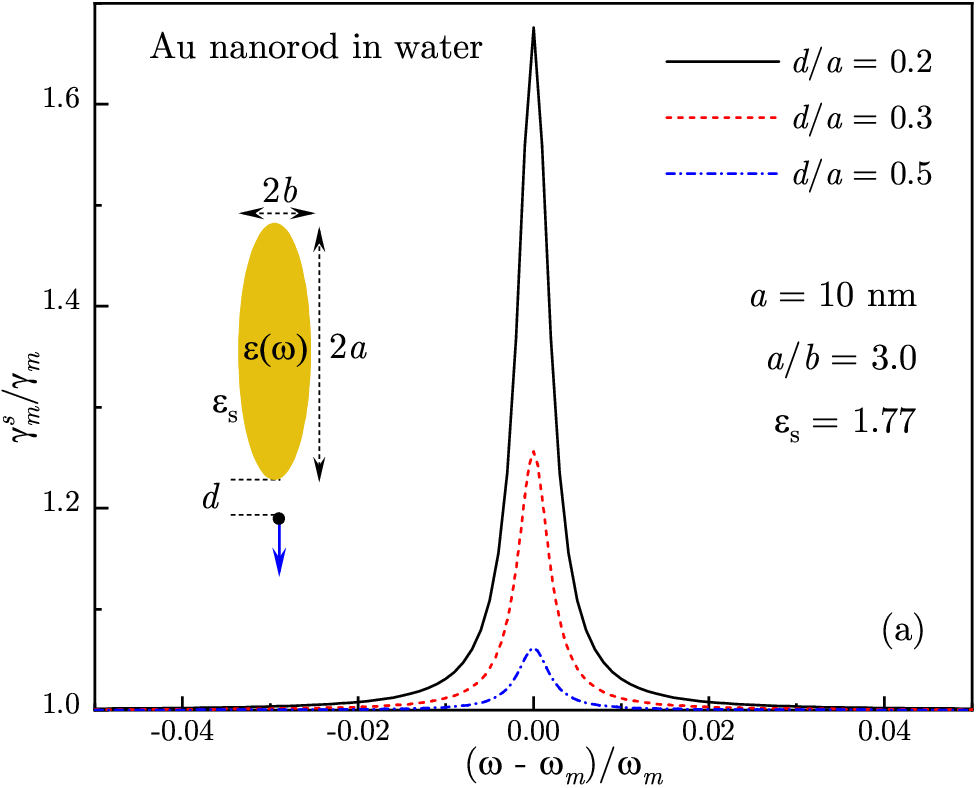
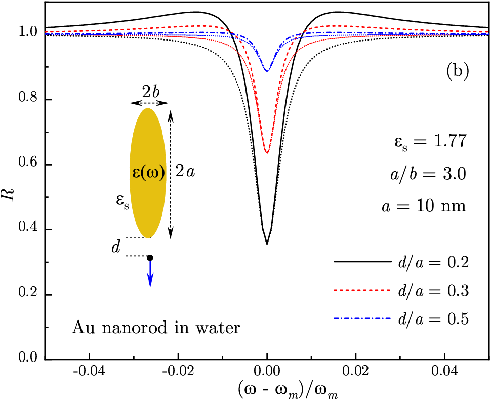
In Fig. 1, we plot the ExIT parameter against the emitter’s distance to nanorod tip for several values of aspect ratio . Note that the Purcell factor is largest near the tip of elongated particles, where the plasmon mode volume is small, so that for the nanorod with aspect ratio (), but it is negligibly small for a nanosphere (). Away from the tip, drops sharply to at . However, even for small values of , the dressed plasmon’s decay rate Eq. (32) still shows a spike at the emitter’s frequency, which develops into a pronounced peak with reducing [see Fig. 2(a)]. This rise of the dressed plasmon decay rate in a narrow frequency region originates from the difference between QE-plasmon and plasmon-QE (back and forth) ET rates in that region [see Eq. (27)]. The same effect defines the shape of function , given by Eq. (29), which modulates the plasmon spectrum [see Fig. 2(b)]. In order to signify the role of ExIT parameter , we also plot the ExIT function , given by Eq. (30), for each value of QE-nanorod distance (dotted lines). Clearly, deep in the weak coupling regime (small ), the ExIT function accurately describes the spectral minimum (blue curves), while for larger (i.e., closer to the tip) the spectrum develops ”wings” outside the dip region as the system approaches the strong coupling transition point. Importantly, for any distance , the ExIT function very accurately reproduces the central part of ExIT minimum and, in particular, its amplitude, implying that it is the energy exchange mechanism, rather than a Fano-like interference, which is responsible for ExIT.


In Fig. 3, we plot the normalized scattering cross-section (28) of the hybrid system for several values of . In the weak coupling regime, the overall spectral shape is described by plasmon resonance peak modulated by the ExIT function which exhibits a narrow minimum at the emitter’s frequency . For the emitter and plasmon frequencies in exact resonance (), the ExIT window is positioned at the center of the plasmon spectral band [see Fig. 2(a)], but for blueshifted relative to , the transmission maximum shifts to a higher frequency as well [see Fig. 2(b)]. The fact that the ExIT window is always centered at the emitter’s absorption peak position, as described by Eq. (30), is readily consistent with the energy exchange mechanism of ExIT but has no natural interpretation in terms of Fano interference. Note that, even at exact resonance (), the double-peak spectrum is asymmetric [see Fig. 2(a)] since the scattering cross-section is proportional to [see Eq. (7)], reflecting the fact that, for higher frequencies, the reemission takes place at a higher rate (). Finally, the emergence of ExIT window is not characterized by any clear onset, implying the absence of a distinct ”intermediate” coupling phase.
V Conclusions
In summary, we developed a model for exciton-induced transparency in hybrid plasmonic systems based on an energy exchange mechanism between the system components. For a single emitter resonantly coupled to a surface plasmon in a metal-dielectric structure, we derived an effective optical polarizability that includes exciton-plasmon coupling expressed in terms of the energy transfer rate. We analyzed in detail possible ExIT mechanisms to show that the spectral minimum in the weak coupling regime results from the energy exchange imbalance between the system components in a narrow frequency interval. We derived in analytic form a frequency-dependent function that describes accurately the shape and amplitude of the transparency window centered at the emitter absorption peak position.
Acknowledgements.
This work was supported in part by National Science Foundation Grants No. DMR-2000170, No. DMR-1856515, No. DMR-1826886, and No. HRD-1547754.References
- (1) T. Schwartz, J. A. Hutchison, C. Genet, and T. W. Ebbesen, Phys. Rev. Lett. 106, 196405 (2011).
- (2) A.-L. Baudrion, A. Perron, A. Veltri, A. Bouhelier, P.-M. Adam, and R. Bachelot, Nano Lett. 13, 282–286 (2013).
- (3) L. Lin, M. Wang, X. Wei, X. Peng, C. Xie, and Y. Zheng, Nano Lett. 16, 7655–7663 (2016).
- (4) S. Sun, H. Kim, G. S. Solomon, and E. Waks, Nat. Nanotechnol. 11, 539–544 (2016).
- (5) L. De Santis, C. Anton, B. Reznychenko, N. Somaschi, G. Coppola, J. Senellart, C. Gomez, A. Lemaitre, I. Sagnes, A. G. White, L. Lanco, A. Auffeves, and P. Senellart, Nat. Nanotech 12, 663–667 (2017).
- (6) A. Tsargorodska, M. L. Cartron, C. Vasilev, G.Kodali, O. A. Mass, J. J. Baumberg, P. L. Dutton, C. N. Hunter, P. Törmä, and G. J. Leggett, Nano Lett. 16, 6850-6856 (2016).
- (7) T. V. Shahbazyan, Nano Lett. 19, 3273–3279 (2019).
- (8) L. Novotny and B. Hecht, Principles of Nano-Optics (CUP, New York, 2012).
- (9) J. P. Reithmaier, G. Sek, A. Löffler, C. Hofmann, S. Kuhn, S. Reitzenstein, L. V. Keldysh, V. D. Kulakovskii, T. L. Reinecke, and A. Forchel, Nature 432, 197 (2004).
- (10) G. Khitrova, H. M. Gibbs, M. Kira, S. W. Koch, and A. Scherer, Nature Phys. 2, 81 (2006).
- (11) K. Hennessy, A. Badolato, M. Winger, D. Gerace, M. Atatüre, S. Gulde, S. Fält, E. L. Hu, and A. Imamoglu, Nature 445, 896 (2006).
- (12) J. Bellessa, C. Bonnand, J. C. Plenet, and J. Mugnier, Phys. Rev. Lett. 93, 036404 (2004).
- (13) Y. Sugawara, T. A. Kelf, J. J. Baumberg, M. E. Abdelsalam, and P. N. Bartlett, Phys. Rev. Lett. 97, 266808 (2006).
- (14) G. A. Wurtz, P. R. Evans, W. Hendren, R. Atkinson, W. Dickson, R. J. Pollard, A. V. Zayats, W. Harrison, and C. Bower, Nano Lett. 7, 1297 (2007).
- (15) N. T. Fofang, T.-H. Park, O. Neumann, N. A. Mirin, P. Nordlander, and N. J. Halas, Nano Lett. 8, 3481 (2008).
- (16) S. Aberra Guebrou, C. Symonds, E. Homeyer, J. C. Plenet, Y. N. Gartstein, V. M. Agranovich, and J. Bellessa, Phys. Rev. Lett. 108, 066401 (2012).
- (17) J. Bellessa, C. Symonds, K. Vynck, A. Lemaitre, A. Brioude, L. Beaur, J. C. Plenet, P. Viste, D. Felbacq, E. Cambril, and P. Valvin, Phys. Rev. B 80, 033303 (2009).
- (18) A. E. Schlather, N. Large, A. S. Urban, P. Nordlander, and N. J. Halas, Nano Lett. 13, 3281 (2013).
- (19) W. Wang, P. Vasa, R. Pomraenke, R. Vogelgesang, A. De Sio, E. Sommer, M. Maiuri, C. Manzoni, G. Cerullo, and C. Lienau, ACS Nano 8, 1056 (2014).
- (20) G. Zengin, M. Wersäll, S. Nilsson, T. J. Antosiewicz, M. Käll, T. Shegai, Phys. Rev. Lett. 114, 157401 (2015).
- (21) M. Wersäll, J. Cuadra, T. J. Antosiewicz, S. Balci, and T. Shegai, Nano Lett. 17, 551-558 (2017).
- (22) M. Wersäll, B. Munkhbat, D. G. Baranov, F. Herrera, J. Cao, T. J. Antosiewicz, and T. Shegai, ACS Photonics 6, 2570–2576 (2019).
- (23) T. K. Hakala, J. J. Toppari, A. Kuzyk, M. Pettersson, H. Tikkanen, H. Kunttu, and P. Torma, Phys. Rev. Lett. 103, 053602 (2009).
- (24) A. Berrier, R. Cools, C. Arnold, P. Offermans, M. Crego-Calama, S. H. Brongersma, and J. Gomez-Rivas, ACS Nano 5, 6226 (2011).
- (25) A. Salomon, R. J. Gordon, Y. Prior, T. Seideman, and M. Sukharev, Phys. Rev. Lett. 109, 073002 (2012).
- (26) A. De Luca, R. Dhama, A. R. Rashed, C. Coutant, S. Ravaine, P. Barois, M. Infusino, and G. Strangi, Appl. Phys. Lett. 104, 103103 (2014).
- (27) V. N. Peters, T. U. Tumkur, Jing Ma, N. A. Kotov, and M. A. Noginov, Opt. Express 24, 25653 (2016).
- (28) P. Vasa, R. Pomraenke, S. Schwieger, Y. I. Mazur, V. Kunets, P. Srinivasan, E. Johnson, J. E. Kihm, D. S. Kim, E. Runge, G. Salamo, and C. Lienau, Phys. Rev. Lett. 101, 116801 (2008).
- (29) D. E. Gomez, K. C. Vernon, P. Mulvaney, and T. J. Davis, Nano Lett. 10, 274 (2010).
- (30) D. E. Gomez, S. S. Lo, T. J. Davis, and G. V. Hartland, J. Phys. Chem. B 117, 4340 (2013).
- (31) A. Manjavacas, F. J. Garcia de Abajo, and P. Nordlander, Nano Lett. 11, 2318 (2011).
- (32) B. J. Lawrie, K.-W. Kim, D. P. Norton, and R. F. Haglund Jr., Nano Lett. 12, 6152 (2012).
- (33) E. Waks and J. Vuckovic, Phys. Rev. Lett. 96, 153601 (2006).
- (34) R. D. Artuso and G. W. Bryant, Phys. Rev. B 82, 195419 (2010).
- (35) X. Wu, S. K. Gray, and M. Pelton, Optics Express 18, 23633-23645 (2010).
- (36) H. Leng, B. Szychowski, M.-C. Daniel, and M. Pelton, Nat. Comm. 9, 4012 (2018).
- (37) M. Pelton, S. D. Storm, and H. Leng, Nanoscale 11, 14540-14552 ( 2019).
- (38) K. Santhosh, O. Bitton, L. Chuntonov, and G. Haran, Nat. Commun. 7, 11823 (2016).
- (39) R. Chikkaraddy, B. de Nijs, F. Benz, S. J. Barrow, O. A. Scherman, E. Rosta, A. Demetriadou, P. Fox, O. Hess, and J. J. Baumberg, Nature 535, 127–130 (2016).
- (40) P. Vasa and C. Lienau, ACS Phot. 5, 2–23 (2018).
- (41) D. G. Baranov, M. Wersall, J. Cuadra, T. J. Antosiewicz, and T. Shegai, ACS Phot. 5, 24–42 (2018).
- (42) J. Wen, H. Wang, W. Wang, Z. Deng, C. Zhuang, Y. Zhang, F. Liu, J. She, J. Chen , H. Chen, S. Deng, and N. Xu, Nano Lett. 17, 4689–4697 (2017).
- (43) A. Krasnok, S. Lepeshov, and A. Alu, Optics Express 26, 15972 (2018).
- (44) C. Schneider, M. M. Glazov, T. Korn, S. Höfling, and B. Urbaszek, Nat. Comm. 9, 2695 (2018).
- (45) M. Stührenberg, B. Munkhbat, D. G. Baranov, J. Cuadra, A. B. Yankovich, T. J. Antosiewicz, E. Olsson, and T. Shegai, Nano Lett. 18, 5938–5945 (2018).
- (46) W. Du, J. Zhao, W. Zhao, S. Zhang, H. Xu, and Q. Xiong, ACS Phot. 6, 2832–2840 (2019).
- (47) H. Gross, J. M. Hamm, T. Tufarelli, O. Hess, and B. Hecht, Sci. Adv. 4, eaar4906 (2018).
- (48) K.-D. Park, M. A. May, H. Leng, J. Wang, J. A. Kropp, T. Gougousi, M. Pelton, and M. B. Raschke, Sci. Adv. 5, eaav5931 (2019).
- (49) J. J. Baumberg, J. Aizpurua, M. H. Mikkelsen, and D. R. Smith, Nat. Mater. 8, 668–678 (2019).
- (50) M. I. Stockman, in Plasmonics: Theory and Applications, edited by T. V. Shahbazyan and M. I. Stockman (Springer, New York, 2013).
- (51) T. V. Shahbazyan, Phys. Rev. B 98, 115401 (2018).
- (52) L. D. Landau and E. M. Lifshitz, Electrodynamics of Continuous Media (Elsevier, Amsterdam, 2004).
- (53) T. V. Shahbazyan, Phys. Rev. Lett. 117, 207401 (2016).
- (54) T. V. Shahbazyan, ACS Photon. 4, 1003 (2017).
- (55) P. B. Johnson and R. W. Christy, Phys. Rev. B 6, 4370 (1972).