A Lifting Wing Fixed on Multirotor UAVs for Long Flight Ranges
Abstract
This paper presents a lifting-wing multirotor UAV that allows long-range flight. The UAV features a lifting wing in a special mounting angle that works together with rotors to supply lift when it flies forward, achieving a reduction in energy consumption and improvement of flight range compared to traditional multirotor UAVs. Its dynamic model is built according to the classical multirotor theory and the fixed-wing theory, as the aerodynamics of its multiple propellers and that of its lifting wing are almost decoupled. Its design takes into consideration aerodynamics, airframe configuration and the mounting angle. The performance of the UAV is verified by experiments, which show that the lifting wing saves 50.14% of the power when the UAV flies at the cruise speed (15m/s).
keywords
Lifting wing, Multirotor, UAV, Optimization, Long flight range1 Introduction
1.1 Lifting-wing multirotor UAV
Nowadays, multirotor UAVs have been developing rapidly in consumer and industrial markets owing to their advantages of vertical take-off and landing, good maneuverability and stability, and simple configuration[1]. However, their operation range is poorer than that of fixed-wing aircraft; thus, they are not preferred when executing certain tasks such as transport and long-distance reconnaissance[2]. This motivates to improve range and payload of multirotor UAVs[3].
The general method to do this is to optimize propulsion systems. Dai et al. [4, 5, 6] proposed an analytical design optimization method for electric propulsion systems of multirotor UAVs. Magnussen et al. [7] proposed a design optimization method considering the number of actuators. Deters and Selig [8] and Ol et al. [9] contributed to characterize and optimize propeller performance. In addition to propulsion system optimization, aerodynamic optimization of fuselage is an effective way to improve range and payload. However, to the best of our knowledge, there are limited academic works on aerodynamic optimization of fuselage for multirotor UAVs. Hwang et al. [10] conducted a numerical study of aerodynamic performance of multirotor UAVs, Bannwarth et al. [11] built a novel multirotor UAV aerodynamic model; however, they did not carry out the optimization research. Compared with the academic world, industries pay more attention to aerodynamic optimization. Fig. 1 shows a few multirotor UAV products [12, 13, 14] with aerodynamic optimization. It is evident that engineers focus on cutting down drag; however, it is known that for an aircraft, there is not only drag, but also lift.


As shown in Fig. 2, the key idea of our research is to study a new type of multirotor UAVs, namely the lifting-wing multirotor UAVs, which provides a multirotor UAV with a short wing installed at a specific mounting angle. The lifting-wing multirotor UAV only has to tilt a specific angle often smaller than 45 degrees to perform forward flight. After that, both rotors and the lifting wing supply lift, thus reducing the energy consumption and improving its range compared with the corresponding multirotor UAV. Moreover, as shown in Fig. 2, it does not have a tailfin. Instead, its function is replaced by the yaw control of the multirotor UAV component. In order to increase the yaw control ability, the axes of rotors do not point only upward any more (as shown in Fig. 2(a)). This implies that the thrust component by rotors can change the yaw directly rather than merely counting on the reaction torque of rotors. From the above, the wind interference is significantly reduced on the one hand; on the other hand, the yaw control ability is improved. As a result, it can have better maneuverability and hover control to resist the disturbance of wind than those by current hybrid UAVs. As a preliminary study on the lifting-wing multirotor UAV, the design from the aspects of aerodynamics, airframe configuration and wing’s mounting angle will be discussed. Also, the performance test is analyzed. Expectantly, the test results show that the lifting wing saves 50.14% power at the cruise speed (15 m/s).
The main contributions of this paper are: i) an analysis that aerodynamics of multiple propellers and the lifting wing are almost decoupled; ii) a method to determine the mounted angle of the lifting wing; iii) the experimental study to show power saving.
1.2 Comparison with other UAVs
The lifting-wing multirotor UAV is a type of multirotor UAVs. But, it is necessary to compare with existing fixed-wing Vertical/Short Take-Off and Landing (V/STOL) UAVs, or hybrid UAVs in other words. V/STOL aerodynamic is concerned primarily with the production of lift at low forward velocities [15]. V/STOL UAVs in most time work as fixed-wing UAVs. Thus, its hovering performance is considerably degraded by the wind disturbance that is introduced by the wing [16]. According to a survey research [17], hybrid UAVs with multiple rotors are classified into multirotor tilt-rotor convertiplane, multirotor tilt-wing convertiplane, multirotor dual-system convertiplane and multirotor tailsitter. Fig. 3 shows these different kind of hybrid UAVs [18, 19, 20, 21]. A comparison among different UAVs is listed as Table 1. As shown, our proposed design is a trade-off between the mutlicopter and the fixed-wing airplane.

![[Uncaptioned image]](2006.15579v2/comparison.png)
2 Aerodynamics and Airframe Configurations
In the introduction, it’s shown that improving lift is more effective than cutting down fuselage drag to improve range and payload. The opinion can be explained through Fig. 4. The illustration, which comes from [22], shows that parasite (drag caused by fuselage) has very little proportion under 20 m/s. Most of the power cost comes from the propeller; thus, the effect of reducing fuselage drag is limited.
Relatively, improving lift is an effective way, for it can reduce the need of the component of propeller thrust in the vertical direction, which means the component of the propeller thrust in the horizontal direction increases. Therefore, the fuselage is designed as a lifting wing.
An important question concerning the lifting wing design should be addressed: Does the fluid field caused by propellers influence the relative flow in front of the lifting wing? Fig. 5 shows that the influence is little beyond 0.8 radius of propeller. And Fig. 2(c) shows that the position of the leading edge and the trailing edge are both beyond 0.8 radius of propellers. Therefore, the wing theory of fixed-wing aircraft can be used for the lifting wing, which makes the design have rules to obey.


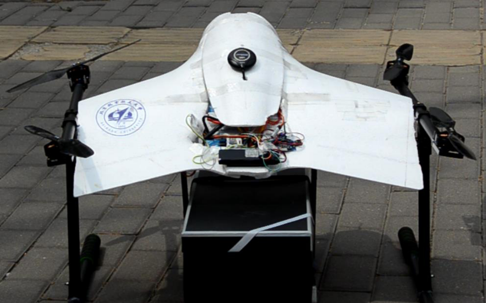
For the experiment prototype, Skywalker X5 Blended Wing Body aircraft is reshaped for the lifting wing. Fig. 6 shows the manner in which the wing is reshaped. The length of the wingspan is reduced and the winglets are removed. Although in this way lift is reduced,additional force and moment disturbances are reduced considerably, thus, achieving a trade-off between range and wind resistance.

The yawing control moment of the multirotor UAV is caused by the air resistance moment of the propeller rotation. Therefore, the yawing control moment is weaker than the pitching and rolling control moments that are caused by different thrusts. Considering that the lifting wing will lead to an additional yawing moment when meeting with a crosswind, the yawing control moment should be improved. Therefore, the propellers in the prototype are tilted fixedly around two arms respectively, as shown in Fig. 2(a). Hence, the different thrusts lead to yawing control moment, improving the control performance.
3 Mounting Angle Optimization
The mounting angle is a term in fixed-wing aircraft, which is the angle between the chord line of the wing and a reference axis along the fuselage [24]. For our proposed design, the mounting angle also exists, which relates the two key angles, angle of attack that decides the lift force, and pitch angle that decides the ratio of the vertical components of thrust to the horizontal components. Their relationship is shown as Equation (1) and Fig. 2(b).
| (1) |
In this section, the mounting angle is optimized and the cruise speed is determined for the purpose of obtaining the longest range.
3.1 Optimization Model
The optimization model is based on the assumption that there is no wind, and the airframe is perfectly symmetric. The model considers the forward flight. Thus, the roll moment, yaw moment, and lateral force can be neglected. Therefore, the 3D dynamics can be simplified to 2D dynamics
| (2) | ||||
| (3) | ||||
| (4) |
where is the thrust magnitude for one propeller, is the air density, is the airspeed magnitude, is the reference area, is lift coefficient, drag coefficient, is the mass of the aircraft and g is the gravitational acceleration, is the control pitch moment and is the aerodynamic pitch moment.
Considering that four propellers can supply equal resultant force when modifying the resultant moment, Equation (4) can be ignored in the optimization problems because it is not an effective constraint.
Shastry et al. [25] expressed the propeller thrust and torque in their simplified model as
| (5) | ||||
| (6) |
where is the propeller thrust coefficient, and is the propeller torque coefficient. Both and depend on the rotation speed and air speed perpendicular to the propeller disk . Without considering the environment wind, can be expressed as
| (7) |
Therefore Equations (5) (6) can be written as Equations (8) (9) for the propeller.
| (8) | ||||
| (9) |
In addition to the force and moment equations, electrical equations are also part of the constraints of the optimization.
| (10) | ||||
| (11) |
where is the current of one electronic speed controller, is the battery power capability, and is the flight duration.
, and Equations (8) (9) (10) (11) are fitted according to experiment data, which is presented in detail in Appendix.
The objective function is , and according to the constraint equations, the optimization model can be expressed as
| (12) |
3.2 Optimization Solution
Equation (12) is a nonlinear programming problem. Considering limited mechanical assembly accuracy, the mounting angle cannot be very precise; therefore, we use the method of exhaustion. To avoid a stall and consider the pitch angle limit, we set the enumeration range from 0 to (the stall attack angle), and the installation angle ranges from to degree. Therefore, 900 steps are conducted in the solution.
- 1.
For a single curve, there is a maximum.
- 2.
As the attack angle increases, the maximum increases and the maximum point moves toward the right (therefore some maximum points are out of the x-axis range).

To avoid a stall, we set as the safety margin of the attack angle. Fig. 7(b) shows the limit of attack angle. The flight range achieves its maximum (12.3 km) at mounting angle and attack angle. Under this condition, the flight speed is 15.3 m/s. Therefore, we determine the mounting angle as , and the cruise speed as 15 m/s.
4 Experiment Verification
In order to verify the proposed theory, a prototype was developed, and numerous outdoor flight experiments were conducted. A video which shows the experiments is available at
4.1 Experiment Settings
Fig. 8 shows the prototype, whose weight is 2 kg, and diagonal size is 850 mm. The framework is made of carbon fiber, and the lifting wing is mounted on the framework. The flight controller is Pixhawk** * http://pixhawk.org (open source hardware) along with Ardupilot†† † http://ardupilot.org (open source software). We control the lifting-wing multirotor UAV under the multirotor UAV control mode by taking the aerodynamic force and moment as disturbance.
The flight environment is shown in Google Earth in Fig. 9. The flight distance is approximately one kilometer, which is sufficiently long for the aircraft to take adequate number of samples. For the purpose of quantitative research, all the experiments were conducted in slightly windy conditions (less than 2 m/s)‡‡ ‡ We conducted a qualitative wind resistant experiment under the condition of Scale 5 wind. The prototype succeeded in taking off, 10 m/s flight and landing. The quantitative research of the wind resistant performance is our future work.. We analyze the flight performance including the control performance and power consumption by analyzing the flight logs stored in the controller.
4.2 Control Performance Test
In the current flight mission, the flight speed is under 20 m/s, so the additional aerodynamic force and moment can be considered as environment disturbance. Therefore, the prototype is armed with the conventional multirotor UAV controller which works well. Fig.9 shows that the prototype tracks the desired trajectory well. Furthermore, Fig. 10 shows that the three attitude angles are tracked well during the 15 m/s flight (including the adjustment period).


4.3 Power Consumption Test
To test the power consumption, which is the key to the performance of our proposed design, we conducted a control experiment. The control arm, as Fig. 11 shows, is a conventional multirotor UAV. For scientific control, it is the same as the experiment arm (the prototype), except that it does not have a lifting wing.

Table 2 compares the power consumption of the experiment arm with that of the control arm. The real-time power is obtained from the flight logs. The greater the flight speed is, the larger percent of power is saved by the lifting wing. At 15 m/s (cruise speed), it saves 50.14% power .
| Flight speed | Power of control arm | Power of experiment arm | Power Save |
|---|---|---|---|
| 5 m/s | 2.436 mAh/s | 2.351 mAh/s | 3.49% |
| 10 m/s | 2.735 mAh/s | 1.921 mAh/s | 29.76% |
| 15 m/s(cruise speed) | 5.287 mAh/s | 2.636 mAh/s | 50.14% |
5 Conclusion
The lifting wing design for multirotor UAVs is presented. The lifting wing provides additional lift force, which saves power, thus increasing the flight range. It is demonstrated that the aerodynamics of multiple propellers and the lifting wing are almost decoupled. Moreover, the mounting angle is optimized to obtain the maximum flight range and determine the cruise speed. The experiment test shows that the lifting wing design saves power, and the greater the flight speed, the larger the percent of power is saved. For the cruise speed of 15 m/s, the prototype saves 50.14% power. In the current work, a conventional multirotor UAV controller is applied to the lifting-wing multirotor UAV. This control scheme works well in the current flight mission; however, its performance worsens when the flight speed is greater than 20 m/s. The future work will focus on exploiting the aerodynamic force and moment to achieve a better control performance by adding control surfaces and designing a new controller.
6 Appendix
6.1 Obtaining and
The aerodynamic coefficients are obtained from the wind tunnel experiments from [26], which introduces a VTOL UAV that also uses Skywalker X5 as the aerodynamic configurations. After the linear fitting, the expressions are obtained as
| (13) | ||||
| (14) |
6.2 Obtaining and
The propeller data is obtained from the APC Propeller official website11 1 https://www.apcprop.com/files. The dataset contains different types of data, among which , , , and are required. Equations (8) (9) are expressed as Equations (15) (16). The coefficients of correlation of the two fitting are 0.99993 and 0.99999.
| (15) | ||||
| (16) | ||||
6.3 Obtaining
The propulsion system experiment measurement was conducted using RCbenchmark Series 1580 Thrust Stand and Dynamometer11 1 https://www.rcbenchmark.com/products/dynamometer-series-1580.
We conducted four samplings with different rotation speeds and fitted the data with the quadratic function. The coefficient of the correlation is 0.9997, and the expression is as follows.
| (17) |
References
- [1] Erkol HO. Attitude controller optimization of four-rotor unmanned air vehicle. International Journal of Micro Air Vehicles 2018; 10(1): 42–49.
- [2] Saggiani GM and Teodorani B. Rotary wing UAV potential applications: an analytical study through a matrix method. Aircraft Engineering & Aerospace Technology An International Journal 2004; 76(1): 6–14.
- [3] Hassanalian M and Abdelkefi A. Classifications, applications, and design challenges of drones: A review. Progress in Aerospace Sciences 2017; 91(may): 99–131.
- [4] Dai X, Quan Q, Ren J et al. An analytical design-optimization method for electric propulsion systems of multicopter UAVs with desired hovering endurance. IEEE/ASME Transactions on Mechatronics 2019; 24(1): 228–239.
- [5] Shi D, Dai X, Zhang X et al. A practical performance evaluation method for electric multicopters. IEEE/ASME Transactions on Mechatronics 2017; 22(3): 1337–1348.
- [6] Dai X, Quan Q, Ren J et al. Efficiency optimization and component selection for propulsion systems of electric multicopters. IEEE Transactions on Industrial Electronics 2019; 66(10): 7800–7809.
- [7] Magnussen Ø, Hovland G and Ottestad M. Multicopter UAV design optimization. In 2014 IEEE/ASME 10th International Conference on Mechatronic and Embedded Systems and Applications (MESA). pp. 1–6.
- [8] Deters R and Selig M. Static testing of micro propellers. In 26th AIAA Applied Aerodynamics Conference. AIAA Paper 2008-6246.
- [9] Ol M, Zeune C and Logan M. Analytical/experimental comparison for small electric unmanned air vehicle propellers. In 26th AIAA Applied Aerodynamics Conference. AIAA Paper 2008-7345.
- [10] Hwang JY, Jung MK and Kwon OJ. Numerical study of aerodynamic performance of a multirotor unmanned-aerial-vehicle configuration. Journal of Aircraft 2015; 52(3): 839–846.
- [11] Bannwarth JXJ, Jeremy Chen Z, Stol KA et al. Aerodynamic force modeling of multirotor unmanned aerial vehicles. AIAA Journal 2019; 57(3): 1250–1259.
- [12] Dji phantom 4 pro v2.0. https://www.dji.com/cn/phantom-4-pro-v2?site=brandsite&from=nav. [Online, cited 28 March 2020].
- [13] Dji inspire 2. https://www.dji.com/cn/inspire-2?site=brandsite&from=nav. [Online, cited 28 March 2020].
- [14] Microdrones md4-3000. https://www.infomar.ie/surveys/drones/microdrones-md4-3000. [Online, cited 28 March 2020].
- [15] McCormick BW. Aerodynamics of V/STOL flight. Courier Corporation, 1999.
- [16] Zhang H, Song B, Wang H et al. A method for evaluating the wind disturbance rejection capability of a hybrid UAV in the quadrotor mode. International Journal of Micro Air Vehicles 2019; 11.
- [17] Saeed AS, Younes AB, Cai C et al. A survey of hybrid unmanned aerial vehicles. Progress in Aerospace Sciences 2018; 98: 91 – 105.
- [18] Carlson S. A hybrid tricopter/flying-wing VTOL UAV. In 52nd Aerospace Sciences Meeting. p. 0016.
- [19] Öner KT, Çetinsoy E, SIRIMOĞLU E et al. Mathematical modeling and vertical flight control of a tilt-wing UAV. Turkish Journal of Electrical Engineering & Computer Sciences 2012; 20(1): 149–157.
- [20] Aletky J. Out of the black: SLT VTOL UAV. https://diydrones.com/profiles/blogs/out-of-the-black-slt-vtol-uav. [Online, cited 28 March 2020].
- [21] Google drones tested in queensland. https://www.suasnews.com/2014/08/google-drones-tested-in-queensland/, 2014. [Online, cited 28 March 2020].
- [22] Seddon J and Newman S. Basic Helicopter Aerodynamics. American Institute of Aeronautics and Astronautics, 2001.
- [23] Liu J. Aerodynamic Methodology of a Helicopter Rotor. China Avitaion Industry, 2013(in Chinese).
- [24] Phillips WF. Mechanics of Flight. John Wiley & Sons, 2004.
- [25] Shastry AK, Kothari M and Abhishek A. Generalized flight dynamic model of quadrotor using hybrid blade element momentum theory. Journal of Aircraft 2018; 55(5): 2162–2168.
- [26] Lyu X, Gu H, Zhou J et al. Simulation and flight experiments of a quadrotor tail-sitter vertical take-off and landing unmanned aerial vehicle with wide flight envelope. International Journal of Micro Air Vehicles 2018; 10(4): 303–317.