Intelligent Time-Varying Metasurface Transceiver for Index Modulation in 6G Wireless Networks
Abstract
Index modulation (IM) is one of the candidate technologies for the upcoming sixth generation (6G) wireless communications networks. In this paper, we propose a space-time-modulated reconfigurable intelligent metasurface (RI-MTS) that is configured to implement various frequency-domain IM techniques in a multiple-input multiple-output (MIMO) array configuration. Unlike prior works which mostly analyze signal theory of general RI-MTS IM, we present novel electromagnetics-compliant designs of specific IMs such as sub-carrier index modulation (SIM) and MIMO orthogonal frequency-domain modulation IM (MIMO-OFDM-IM). Our full-wave electromagnetic simulations and analytical computations establish the programmable ability of these transceivers to vary the reflection phase and generate frequency harmonics for IM. Our experiments for bit error rate show that RI-MTS-based SIM and MIMO-OFDM-IM are lower than conventional MIMO-OFDM.
Index Terms:
Index modulation, MIMO, OFDM-IM, reconfigurable intelligent surface, time-varying metasurface.I Introduction
Time-modulated antenna arrays, whose radiated power pattern is steered by varying the width of the periodic pulses applied to each element, are long known to have applications in side-lobe reduction [1, 2], harmonic beamforming [3], and directional modulation in phased arrays [4]. Such arrays based on metasurfaces (MTSs) have drawn significant interest in the engineering community [5] because of their ability to control and manipulate electromagnetic (EM) waves in a sub-wavelength thickness through modified boundary conditions [6, 7]. The MTS, viewed as a two-dimensional (2-D) equivalent of metamaterials, is a synthetic electromagnetic surface composed of sub-wavelength patches, or meta-atoms, printed on one or more dielectric substrate layers [8]. Through careful engineering of each meta-atom, MTSs can transform an incident EM wave into an arbitrarily tailored transmitted or reflected wavefront [9, 10, 11, 12].
Recent developments in spatio-temporally (ST) modulated MTSs have unlocked a new class of nonlinear and nonreciprocal behaviors, including direct modulation of carrier waves [5], programmable frequency conversion [13, 14], controllable frequency harmonic generation [15], and cloaking [16, 15]. These properties are very attractive for designing future low-cost and light-weight wireless communications systems where control of beam-pattern is key to enable reliable and efficient information delivery through massive multiple-input multiple-output (MIMO) antenna arrays [17]. Notably, reconfigurable intelligent MTSs (RI-MTSs) are capable of applying dynamic transformations of EM waves and have been recently proposed as sensors in fifth/sixth-generation (5G/6G) smart radio environments [18]. An RI-MTS employs an array of individually-controllable meta-atoms to scatter incident signals to maximize metrics such as receiver signal-to-noise ratio (SNR) [17]. While several theoretical studies analyze signal processing for 5G/6G RI-MTSs [19, 18, 20] and large intelligent surfaces (LISs) [21], their specific EM analyses remain unexamined.
Contrary to these works, we focus on EM analysis and implementation of RI-MTSs for wireless communications. In particular, we consider transceiver for index modulation (IM) that is identified as one of the preferred 5G/6G technologies [22] largely because of better energy and spectral efficiencies than conventional modulations [23]. The information in IM is encoded through permutations of indices of spatial, frequency, or temporal media. Common IM techniques [24, 25] include spatial modulation [26] and subcarrier IM (SIM) [27].
Our prior work [28] introduced the concept of RIS-based spatial modulation. Motivated by recent research in ST-modulated MTSs, we hereby propose and demonstrate RIS-based designs for a variety of IM techniques such as frequency shift keying (FSK) [29], and orthogonal frequency-division multiplexing (OFDM) with IM (OFDM-IM) [30, 22], and MIMO-OFDM-IM [31]. We implement these frequency-domain IM techniques using the concepts of ST-modulated metamaterials and reflect-array antennas. Our full-wave EM simulations for meta-atom design validate the scattering radiation pattern of our finite RI-MTS array. Finally, we validate the RIS performance using wireless communications model and establish that, despite occupying less spectrum, our proposed designs result in bit error rates (BERs) that are lower than traditional OFDM.
II System Model
Consider a MIMO-OFDM wireless system with transmit and receive antennas. In OFDM, a frequency-selective fading channel is handled by dividing the spectrum into multiple flat-fading subchannels of equal bandwidth [32]. Unlike standard frequency domain modulation where the carriers are non-overlapping and separated by additional guard bands, the gap between OFDM subcarriers is equal to the inverse of the symbol duration. The resulting overlap of subcarriers, with the peak of one coinciding with the nulls of the other, increases the spectral efficiency [33]. Each one of the symbols independently modulates one of the equi-bandwidth OFDM subcarriers that are transmitted simultaneously. The sum of the modulated signals is the complex baseband OFDM signal
| (1) |
where are data symbols and is symbol duration. The length of the entire message bit sequence is , where each message sequence vector is a -bit codeword. The transmit signal at the RF stage is .
For line-of-site (LoS) communications, the multipath fading channel follows a Rician distribution [34]. Here, the complex channel impulse response is modeled as the sum of the fixed LOS component and a random multipath non-LoS (nLoS) channel component as [35]
| (2) |
where is the Rician -factor of the channel, is the LoS channel component that is unchanged during the channel coherence time, and is the nLoS fading component representing random multipath fading. The Rician -factor is the ratio between the power in the direct path (LoS) and the power in the other scattered nLoS paths. Assuming a narrowband block-fading channel, the received signal is
| (3) |
where is the output of receive antennas and is the circularly symmetric white Gaussian noise. The BER is computed after decoding the received symbols usually via maximum likelihood (ML) detector [26].
Current MIMO-OFDM techniques have limited energy efficiency caused by power consumption that increases linearly with radio-frequency (RF) chains [36]. The SIM-OFDM or OFDM-IM overcome this [27]by employing a new dimension of subcarrier index for modulating additional bits in addition to the usual phase and amplitude indices of the signal constellation. In OFDM-IM, of subcarrier are activated per symbol leaving index bits for signaling. More recently, OFDM-IM has been combined with a MIMO configuration to yield MIMO-OFDM-IM which achieves significantly lower BER than the traditional MIMO-OFDM [31]. The number of bits per channel use (bpcu) for MIMO-OFDM-IM is . Note that when in OFDM-IM, the system is equivalent to FSK [24].

In a conventional wireless communication transceiver with a passive reflector (Fig. 1a), modulation is performed using complex RF circuitry in the feed usually only in a single input/output (SI/SO) configuration. For MIMO-based IM, we consider ST-coded RI-MTS (Fig. 1b) comprising an array of meta-atoms, each of which is embedded with a varactor diode and variable resistor to control the time-varying reflection amplitude and phase of each meta-atom. A field programmable gate array (FPGA) controller and multiplexer translates information bits to a ST coding matrix [28].
We model MTS using generalized sheet transition conditions to relate electric field vector , where denotes the transpose, on both sides of the MTS via surface electric susceptibility tensors ] in the Cartesian coordinate system (magnetic field and susceptibility are defined similarly):
| (4) | ||||
| (5) |
where is the unit vector, is the angular frequency, is the gradient operator, subscript “” represents average of fields on either side of MTS, and subscript refers to tangential field components which are transverse to [37]. Our reflect-array MTS is fully reflective with no transmit fields. At the surface of the RI-MTS , the reflected electric field is
| (6) |
where is incident field and is time-varying complex reflection coefficient. Note that , where the complex surface impedance characterises the behavior of each meta-atom and is free-space impedance.
| (7) |
where denotes convolution. Given an incident wave of , the spectrum of the scattered wave is controlled by varying of each meta-atom. If is a periodic signal, then it is a linear combination of complex exponentials [39], i.e., , where is the modulation period, , and is the Fourier series (FS) coefficient of the -th harmonic. The corresponding reflected wave in the spectral-domain is
| (8) |
We ST-modulate for each meta-atom to radiate the th harmonic frequency or a combination of harmonic frequencies to the desired steer angle. We now propose our meta-atom design and determine its steady-state at each coding state.
III Meta-Atom Design for IM Transceivers
Consider a MTS whose meta-atoms are indexed by integers and along - and -axes, respectively. The inter-element spacing in the () dimension is (). Given time-varying complex reflection coefficient of the -th meta-atom, the approximate far-field pattern reflected by a ST-modulated MTS that is illuminated by a plane wave at time is [14, 40]
| (9) |
where and denote angles in spherical coordinates, is the pattern response, and is the wavenumber.
We scan the reflected beam by coding the RI-MTS with a progressively varying phase shift. The phase of each meta-atom is [41]
| (10) |
where , is the desired steering direction of the radiation pattern. The meta-atom response is simulated in HFSS as a unit-cell with periodic boundary conditions. Therefore, we consider local or quasi-periodicity so that the reflection phase is smoothly varying across the MTS [41]. From FS, the -th harmonic of is [14]
| (11) |
where is the number of time-steps in the coding sequence per modulation period . This provides the amplitude and phase of the th frequency harmonic reflected from the RI-MTS as a function of . By varying the slope of the phase coding sequence according to , we shift to [42, 43]. To implement OFDM or OFDM-IM, multiple simultaneous sub-carriers are superimposed to produce
| (12) |
where encapsulates the modulated amplitude and phase of each sub-carrier .
A time shift in the periodic time-varying coding sequence is equivalent to spatial phase shift [14], i.e. . By exploiting this property, we generate the desired IM frequency subcarriers by phase (and/or amplitude) modulation of each meta-atom. As a result, the far-field radiation pattern of the ST RI-MTS at the th harmonic frequency becomes
| (13) |
We use this relation to generate and spatially steer frequency harmonics in a controllable manner for advanced RIS-based modulation, multiplexing, and beamforming.
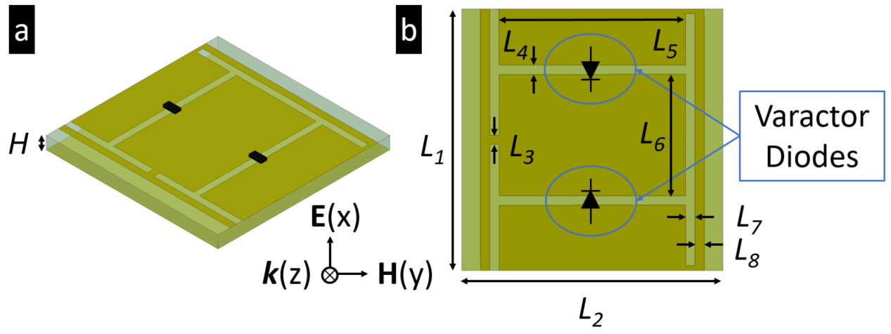


We designed a reflective time-varying MTS (Fig. 2) where each meta-atom unit cell is embedded with two varactor diodes. Figure 2a shows an isometric view of the meta-atom unit cell. To reduce fabrication cost and control complexity, this prototype meta-atom design does not require vias and supports only column-level voltage control. As a result, only 1-D beam scanning is supported in this design. For 2-D beam control, an element-level voltage variation is required to individually address meta-atoms. Among prior works, the closest to our proposed meta-atom is [43]. However, our design is modified for reflective rather than transmit MTS-based phase shifters of [43]. We use embedded MACOM MAVR-000120-14110P gallium arsenide (GaAs) flip chip hyperabrupt varactor diodes [44] with tunable capacitance and resistance in the ranges - pF and - , respectively. The breakdown voltage for the diode is V, allowing a tuning range of - V. The nonlinear Keysight ADS (Advanced Design Systems) diode model that includes losses and capacitance versus reverse bias voltage relationship is available from the manufacturer [44]. Using the S-parameters of the meta-atom simulated in HFSS, we use the ADS diode circuit model to simulate the RF performance of the time-varying meta-atom. We perform ADS harmonic balance simulations to predict response of MTS modulated with a time-varying voltage signal.
We selected the dimensions of the meta-atom (Fig. 2b) to provide an operational reflection phase tuning range of at = 28 GHz, where the meta-atom is relatively low-loss with a reflection amplitude of dB for all simulated tuning states. Figure 3 shows the reflection amplitude and phase response as a function of diode reverse bias voltage. We synthesized the dimensions of the meta-atom unit cell through parametric tuning and trial-and-error iteration in ANSYS HFSS full-wave EM simulations. The tunable reflection phase range and reflection amplitude loss are primarily functions of diode’s capacitance tuning range and its resistance, respectively.
IV Numerical Experiments
We validated our approach and design through numerical simulations. We nominally considered a meta-atom with element spacing of at GHz. The meta-atoms are arranged in columns on a rectangular lattice. Control signals independently address the top and/or bottom half of each column to spatially steer the reflected beam to the desired receiver or create multiple sub-apertures for MIMO and spatial modulation techniques. A larger aperture provides more antenna gain for the transmitter, which results in higher SNR at the receiver, or a greater number of sub-apertures for higher communications capacity.
A time-harmonic phase coding sequence with period s is used to provide MHz harmonic spacing. By specifying the complex weights in (12), we control the amplitude and phase of each harmonic (Fig. 4a-c). Figure 4d-g demonstrate the harmonic generated and steered to the direction . In particular, Fig. 4d depicts the corresponding ST coding matrix. The resulting spectrum of for for to is shown in Fig. 4e. The scanned radiation patterns of the harmonic are shown in Fig. 4f. The full-wave simulation verification of finite RI-MTS array scattered radiation pattern at is plotted in Fig. 4g.
We verified the communications performance of our design through BER performance for RI-MTS-based single-input single-output (SISO) and MIMO-OFDM-IM. In the signal model of (3) for OFDM-IM, we set 2 out of subcarriers and index bits. We benchmark our design against conventional OFDM and PSK systems in terms of their bpcu. Using only out of available subcarriers, this OFDM-IM system achieves a reduction in instantaneous bandwidth compared to traditional OFDM. The number of transmit antennas were the same as the number of receive antennas for each case (). We divided the RI-MTS into 2 and 4 sub-apertures for MIMO operation. We set dB to be consistent with the experimental characterization at GHz [45] and previous analyses of other LIS-based wireless systems [46]. The BER performance of ML symbol detector (Fig. 4h) shows that, for same , , and number of bits per channel use (bpcu), MIMO-OFDM-IM (purple and green; light blue and red curves) outperforms conventional MIMO-OFDM (dark blue; orange curves, respectively). Note that MIMO-OFDM-IM achieves this BER with less spectrum usage.
V Summary
We modeled and demonstrated an ST-modulated RI-MTS to perform key IM schemes for 5G/6G wireless networks. Our RIS-based implementations do not require conventional phase shifters, mixers, or a lossy RF manifold network, but need a control network to individually address the antenna elements. Consequently, these RI-MTS architectures hold the promise to achieve direct frequency modulation and beam scanning in significantly less size, weight, and power consumption compared to conventional phased arrays.
References
- [1] W. Kummer, A. Villeneuve, T. Fong, and F. Terrio, “Ultra-low sidelobes from time-modulated arrays,” IEEE Transactions on Antennas and Propagation, vol. 11, no. 6, pp. 633–639, 1963.
- [2] S. Yang, Y. B. Gan, and A. Qing, “Sideband suppression in time-modulated linear arrays by the differential evolution algorithm,” IEEE Antennas and Wireless Propagation Letters, vol. 1, pp. 173–175, 2002.
- [3] L. Poli, P. Rocca, G. Oliveri, and A. Massa, “Harmonic beamforming in time-modulated linear arrays,” IEEE Transactions on Antennas and Propagation, vol. 59, no. 7, pp. 2538–2545, 2011.
- [4] M. P. Daly and J. T. Bernhard, “Directional modulation technique for phased arrays,” IEEE Transactions on Antennas and Propagation, vol. 57, no. 9, pp. 2633–2640, 2009.
- [5] Y. Hadad, D. Sounas, and A. Alu, “Space-time gradient metasurfaces,” Physical Review B, vol. 92, no. 10, p. 100304, 2015.
- [6] H.-T. Chen, A. J. Taylor, and N. Yu, “A review of metasurfaces: Physics and applications,” Reports on progress in physics, vol. 79, no. 7, p. 076401, 2016.
- [7] S. B. Glybovski, S. A. Tretyakov, P. A. Belov, Y. S. Kivshar, and C. R. Simovski, “Metasurfaces: From microwaves to visible,” Physics Reports, vol. 634, pp. 1–72, 2016.
- [8] Q. Nguyen, K. V. Mishra, and A. I. Zaghloul, “Retrieval of polarizability matrix for metamaterials,” in IEEE International Conference on Microwaves, Communications, Antennas and Electronic Systems, 2019, pp. 1–5.
- [9] J. A. Hodge, K. V. Mishra, and A. I. Zaghloul, “RF metasurface array design using deep convolutional generative adversarial networks,” in IEEE International Symposium on Phased Array Systems and Technology, 2019.
- [10] ——, “Joint multi-layer GAN-based design of tensorial RF metasurfaces,” in IEEE International Workshop on Machine Learning for Signal Processing, 2019, pp. 1–6.
- [11] ——, “Multi-discriminator distributed generative model for multi-layer RF metasurface discovery,” in IEEE Global Conference on Signal and Information Processing, 2019.
- [12] J. A. Hodge, Q. M. Nguyen, and A. I. Zaghloul, “Reflective beam steering of metasurface using circular inter-digitated self-phased pixels/cells,” in General Assembly and Scientific Symposium (GASS) of the International Union of Radio Science (URSI), 2020, in-press.
- [13] M. M. Salary, S. Jafar-Zanjani, and H. Mosallaei, “Electrically tunable harmonics in time-modulated metasurfaces for wavefront engineering,” New Journal of Physics, vol. 20, no. 12, p. 123023, 2018.
- [14] L. Zhang, X. Q. Chen, S. Liu, Q. Zhang, J. Zhao, J. Y. Dai, G. D. Bai, X. Wan, Q. Cheng, G. Castaldi, V. Galdi, and T. J. Cui, “Space-time-coding digital metasurfaces,” Nature Communications, vol. 9, no. 1, p. 4334, 2018.
- [15] A. M. Shaltout, V. M. Shalaev, and M. L. Brongersma, “Spatiotemporal light control with active metasurfaces,” Science, vol. 364, no. 6441, p. 3100, 2019.
- [16] C. Caloz and Z.-L. Deck-Léger, “Spacetime metamaterials, Part I: General concepts,” IEEE Transactions on Antennas and Propagation, 2019.
- [17] K. V. Mishra, J. A. Hodge, and A. I. Zaghloul, “Reconfigurable metasurfaces for radar and communications systems,” in URSI Asia-Pacific Radio Science Conference, 2019, pp. 1–4.
- [18] M. Di Renzo, M. Debbah, D.-T. Phan-Huy, A. Zappone, M.-S. Alouini, C. Yuen, V. Sciancalepore, G. C. Alexandropoulos, J. Hoydis, H. Gacanin, J. de Rosny, A. Bounceur, G. Lerosey, and M. Fink, “Smart radio environments empowered by AI reconfigurable meta-surfaces: An idea whose time has come,” EURASIP Journal on Wireless Communications and Networking, vol. 2019, no. 1, p. 129, 2019.
- [19] E. Basar, M. Di Renzo, J. De Rosny, M. Debbah, M.-S. Alouini, and R. Zhang, “Wireless communications through reconfigurable intelligent surfaces,” IEEE Access, vol. 7, pp. 116 753–116 773, 2019.
- [20] J. A. Hodge, K. V. Mishra, and A. I. Zaghloul, “Coded intelligent surface design for generalized beamspace modulation in massive MIMO communications systems,” in IEEE International Symposium on Antennas and Propagation and USNC-URSI Radio Science Meeting, 2020, in press.
- [21] E. Basar, “Reconfigurable intelligent surface-based index modulation: A new beyond MIMO paradigm for 6G,” arXiv preprint arXiv:1904.06704v2, 2019.
- [22] T. Mao, Q. Wang, Z. Wang, and S. Chen, “Novel index modulation techniques: A survey,” IEEE Communications Surveys & Tutorials, vol. 21, no. 1, pp. 315–348, 2018.
- [23] X. Cheng, M. Zhang, M. Wen, and L. Yang, “Index modulation for 5G: Striving to do more with less,” IEEE Wireless Communications, vol. 25, no. 2, pp. 126–132, 2018.
- [24] N. Ishikawa, S. Sugiura, and L. Hanzo, “50 years of permutation, spatial and index modulation: From classic RF to visible light communications and data storage,” IEEE Communications Surveys & Tutorials, vol. 20, no. 3, pp. 1905–1938, 2018.
- [25] J. A. Hodge, K. V. Mishra, and A. I. Zaghloul, “Media-based modulation with reconfigurable intelligent metasurfaces: Design and performance,” in IEEE International Symposium on Antennas and Propagation and USNC-URSI Radio Science Meeting, 2020, in press.
- [26] E. Basar, “Index modulation techniques for 5G wireless networks,” IEEE Communications Magazine, vol. 54, no. 7, pp. 168–175, 2016.
- [27] R. Abu-Alhiga and H. Haas, “Subcarrier-index modulation OFDM,” in IEEE International Symposium on Personal, Indoor and Mobile Radio Communications, 2009, pp. 177–181.
- [28] J. A. Hodge, K. V. Mishra, and A. I. Zaghloul, “Reconfigurable metasurfaces for index modulation in 5G wireless communications,” in IEEE International Applied Computational Electromagnetics Society Symposium, 2019, pp. 1–2.
- [29] Z. Bouida, H. El-Sallabi, A. Ghrayeb, and K. A. Qaraqe, “Reconfigurable antenna-based space-shift keying (SSK) for MIMO Rician channels,” IEEE Transactions on Wireless Communications, vol. 15, no. 1, pp. 446–457, 2015.
- [30] E. Başar, Ü. Aygölü, E. Panayırcı, and H. V. Poor, “Orthogonal frequency division multiplexing with index modulation,” IEEE Transactions on Signal Processing, vol. 61, no. 22, pp. 5536–5549, 2013.
- [31] E. Basar, “On multiple-input multiple-output OFDM with index modulation for next generation wireless networks,” IEEE Transactions on Signal Processing, vol. 64, no. 15, pp. 3868–3878, 2016.
- [32] Z. Liu, Y. Xin, and G. B. Giannakis, “Space-time-frequency coded OFDM over frequency-selective fading channels,” IEEE Transactions on Signal Processing, vol. 50, no. 10, pp. 2465–2476, 2002.
- [33] Y. Wu and W. Y. Zou, “Orthogonal frequency division multiplexing: A multi-carrier modulation scheme,” IEEE Transactions on Consumer Electronics, vol. 41, no. 3, pp. 392–399, 1995.
- [34] J. G. Proakis and M. Salehi, Digital Communications, 5th ed. McGraw-Hill, 2008.
- [35] A. Paulraj, A. P. Rohit, R. Nabar, and D. Gore, Introduction to space-time wireless communications. Cambridge University Press, 2003.
- [36] A. M. Elbir and K. V. Mishra, “Joint antenna selection and hybrid beamformer design using unquantized and quantized deep learning networks,” IEEE Transactions on Wireless Communications, vol. 19, no. 3, pp. 1677–1688, 2020.
- [37] C. L. Holloway, E. F. Kuester, J. A. Gordon, J. O’Hara, J. Booth, and D. R. Smith, “An overview of the theory and applications of metasurfaces: The two-dimensional equivalents of metamaterials,” IEEE Antennas and Propagation Magazine, vol. 54, no. 2, pp. 10–35, 2012.
- [38] D. Ramaccia, D. L. Sounas, A. Alù, A. Toscano, and F. Bilotti, “Phase-induced frequency conversion and Doppler effect with time-modulated metasurfaces,” IEEE Transactions on Antennas and Propagation, 2019.
- [39] J. Y. Dai, J. Zhao, Q. Cheng, and T. J. Cui, “Independent control of harmonic amplitudes and phases via a time-domain digital coding metasurface,” Light: Science & Applications, vol. 7, no. 1, p. 90, 2018.
- [40] H. Yang, X. Cao, F. Yang, J. Gao, S. Xu, M. Li, X. Chen, Y. Zhao, Y. Zheng, and S. Li, “A programmable metasurface with dynamic polarization, scattering and focusing control,” Scientific Reports, vol. 6, p. 35692, 2016.
- [41] J. Huang and J. Encinar, Reflectarray Antennas, ser. IEEE Press Series on Electromagnetic Wave Theory. Wiley, 2007.
- [42] R. C. Cumming, “The serrodyne frequency translator,” Proceedings of the IRE, vol. 45, no. 2, pp. 175–186, 1957.
- [43] Z. Wu and A. Grbic, “Serrodyne frequency translation using time-modulated metasurfaces,” IEEE Transactions on Antennas and Propagation, 2019.
- [44] MACOM. (2020) Solderable GaAs constant gamma flip-chip varactor diode. [Online]. Available: https://www.macom.com/products/product-detail/MAVR-000120-14110P
- [45] M. K. Samimi, G. R. MacCartney, S. Sun, and T. S. Rappaport, “28 GHz millimeter-wave ultrawideband small-scale fading models in wireless channels,” in IEEE Vehicular Technology Conference, 2016, pp. 1–6.
- [46] Y. Han, W. Tang, S. Jin, C.-K. Wen, and X. Ma, “Large intelligent surface-assisted wireless communication exploiting statistical CSI,” IEEE Transactions on Vehicular Technology, vol. 68, no. 8, pp. 8238–8242, 2019.