Adaptive Digital PID Control of a Quadcopter with Unknown Dynamics
Abstract
This paper develops an adaptive autopilot for quadcopters with unknown dynamics. To do this, the PX4 autopilot architecture is modified so that the feedback and feedforward controllers are replaced by adaptive control laws based on retrospective cost adaptive control (RCAC). The present paper provides a numerical investigation of the performance of the adaptive autopilot on a quadcopter with unknown dynamics. In order to reflect the absence of prior modeling information, all of the adaptive digital controllers are initialized at zero gains. In addition, moment-of-inertia of the quadcopter is varied to test the robustness of the adaptive autopilot. In all test cases, the vehicle is commanded to follow a given trajectory, and the resulting performance is examined.
I Introduction
Multicopters are ubiquitous and are increasingly used for diverse applications ranging from sports broadcasting to wind-turbine inspection [1, 2, 3, 4, 5]. In the simplest configuration, differential torques applied to the motors of a quadcopter provide thrust for translational motion as well as moments for attitude control. For commercial applications, the autopilot of a quadcopter can be finely tuned and tailored to the geometry and mass properties of the vehicle. In fact, the open-source autopilot PX4 has been used extensively for many vehicle configurations [6].
In some applications, however, the vehicle properties are frequently modified due to changes in the airframe, payload, sensors, and actuators. This occurs especially in experimental situations and field operations. In these cases, there is no guarantee that stock autopilot gains will perform in an acceptable manner. Along the same lines, unanticipated and unknown changes that occur during flight due to failure or damage may significantly degrade the performance of the autopilot.
With this motivation in mind, the present paper develops an adaptive autopilot for quadcopters with unknown dynamics. To do this, the PX4 autopilot architecture is modified so that the feedback and feedforward controllers are replaced by adaptive control laws based on retrospective cost adaptive control (RCAC) [7]. In particular, each PID controller in PX4 is replaced by an adaptive digital PID controller as described in [8]. The adaptive digital PID controller is based on recursive least squares (RLS), and thus involves the update of a matrix of size upto at each time step, which is amenable to real-time implementation on a typical embedded processor used to support the PX4 autopilot.
Fuzzy neural network based sliding mode control was used in [9] to control a UAV in the presence of wind which learned the inverse dynamics of the plant model. However, the autopilot needed P controllers to be suitably initialized to provide sufficient time for learning. In contrast, the adaptive autopilot controllers are initialized at zero in this paper. Retrospective-cost based PID controllers were used in the attitude controller in [10], and were applied with fixed hyperparameters tuning to a quadcopter, a fixed-wing aircraft, and a VTOL aircraft. The present paper extends the work in [10] by replacing all of the controllers in PX4 autopilot with adaptive controllers.
The contribution of the present paper is the development and numerical demonstration of an adaptive digital autopilot for poorly modeled quadcopters. In particular, the present paper provides a numerical investigation of the performance of the adaptive digital PID autopilot on a quadcopter with unknown dynamics. In order to reflect the absence of prior modeling information, all of the adaptive digital controllers gains are initialized at zero. Next, the effect of tuning hyperparameters of the adaptive digital controllers on the closed-loop performance is investigated. Finally, the moment-of-inertia of the quadcopter is scaled by a factor of five and the adaptive autopilot with fixed tuning hyperparameters is applied to follow a given trajectory. In addition, the evolution of the adaptive controller gains is examined in order to compare the converged controller gains to the stock gains.
The paper is organized as follows. In section II, the quadcopter dynamics is summarized. In section III, the retrospective cost based adaptive PID control algorithm is presented. In section IV, the control architectures of stock PX4 autopilot and the adaptive PX4 autopilot are presented. In section V, simulation results are presented to compare the performance of the adaptive PX4 autopilot with the stock PX4 autopilot. Finally, section VI concludes the paper with the summary of the paper and future directions.
II Quadcopter Dynamics
The Earth frame and quadcopter body-fixed frame are denoted by the row vectrices and , respectively. We assume that is an inertial frame and the Earth is flat. The origin of is any convenient point fixed on the Earth. The axes and are horizontal, while the axis points downward. is defined with and in the plane of the rotors, and points downward, that is, . Assuming that points North and points East, it follows that the Earth frame is a local NED frame. The quadcopter frame is obtained by applying a 3-2-1 rotation sequence to the Earth frame , where the 3-2-1 Euler angles denote yaw, pitch, and roll angles, respectively.
The translational equations of motion of the quadcopter are given by
| (1) |
where is the mass of the quadcopter, is the center-of-mass of the quadcopter, is the physical vector representing the position of the center-of-mass of the quadcopter relative to , , and . Let
| (2) | ||||
| (3) |
Neglecting the gyroscopic moments due to the rotors’ inertia, drag forces, and moments, the rotational equations of motion of the quadcopter in coordinate-free form are given by
| (10) |
where is the inertia tensor of the quadcopter, is the moment applied to the quadcopter relative to , and is the angular velocity of frame relative to the inertial Earth frame It follows from (10) that
| (11) | ||||
| (12) | ||||
| (13) | ||||
| (14) | ||||
| (15) | ||||
| (16) |
III Adaptive Digital PID Control Algorithm
The quadcopter is controlled by a digital controller operating in a sampled-data feedback loop. In particular, consider the PID controller
| (17) |
where are time-varying gains to be adapted, is an error variable, and, for all ,
| (18) |
Note that the integrator state can be computed recursively using . Finally, note that the control (17) can be written as
| (19) |
where, for all ,
To determine the controller gains , let , and consider the retrospective performance variable defined by
| (23) |
where is either or depending on whether the sign of the leading numerator coefficient of the transfer function from to is positive or negative, respectively. Furthermore, define the retrospective cost function by
| (24) |
where is the initial vector of PID gains and is positive definite. For all examples in this paper, we set ; however, can be initialized to nonzero gains in practice if desired.
IV Adaptive Autopilot
In this section, the control architecture for flight control of a quadcopter is presented. The control architecture, shown in Figure 1(a), consists of a mission planner, which generates the specified trajectory, and the PX4 autopilot. The PX4 autopilot contains a position controller in the outer loop, which generates the specified force using position and velocity measurements, and an attitude controller in the inner loop, which generates the angular acceleration required to follow the specified trajectory using Euler-angle and angular-velocity measurements. Finally, depending on the geometry of the quadcopter, the angular acceleration is converted to the angular speeds of the quadcopter motors.
The position controller shown in Figure 1(b) consists of three P controllers, which generate the specified velocities to be followed in the Earth frame using the position feedback, and three PID controllers, which generate the specified forces to be applied in the Earth frame using the velocity feedback.
Next, the attitude controller shown in Figure 1(c) converts the specified forces and the specified yaw to specified Euler angles. The P controller generates the specified Euler angle rates, which are converted to the specified angular velocity using the appropriate orientation matrix. Finally, three feedforward and three PID controllers generate the angular-acceleration commands, which are converted to angular speeds of the quadcopter motors using a static map based on the geometry of the quadcopter.
The adaptive autopilot is constructed by modifying the PX4 autopilot. As shown in Figure 1, the PX4 autopilot consists of three P controllers and three PID controllers in the position controller, and three P constroller, three static-feedforward controllers, and three PID controllers in the attitude controller.
The adaptive autopilot consists of a total of twelve adaptive digital controllers, of which, six are adaptive P, three are adaptive PI, and three are adaptive PID with feedforward. In particular, the fixed-gain P controllers and in the position controller and the attitude controller are replaced by the adaptive P controllers, the fixed-gain PID controllers in the position controller are replaced by the adaptive PI controllers, and the fixed-gain feedforward controllers and the fixed-gain PID controllers in the attitude controller are replaced by adaptive feedforward and PID controllers. The modified adaptive PX4 autopilot is shown in Figure 2.
In the position controller, the adaptive controller is implemented as follows. The error variable and the control are defined by
where , , and are the specified positions given by the mission planner, , , and are the measured positions, and , , and are the specified translational velocities in the inertial frame . Note that sec in the adaptive controller. Finally, for , the control is given by
| (34) |
where is given by (26). Note that the three adaptive controllers in the adaptive controller are decoupled, and hence each channel gain is independently computed using (26), (27).
Next, in the position controller, the adaptive controller is implemented as follows. The error variable and the control are defined by
where , , and are the measured translational velocities in the inertial frame , and , , and are the specified forces in the inertial frame . Note that sec in the adaptive controller. Finally, for , the control is given by
| (41) |
where and . Note that the three adaptive controllers in the adaptive controller are decoupled, and hence the gains of each channel are independently computed using (26), (27).
In the attitude controller, the adaptive controller is implemented as follows. The error variable and the control are defined by
where , , and are the specified Euler angles, , , and are the measured Euler angles, and , , and are the commanded Euler angle rates. Note that sec in the adaptive controller. Finally, for , the control is given by
| (48) |
where is given by (26). Note that the three adaptive controllers in the adaptive controller are decoupled, and hence each channel gain is independently computed using (26), (27).
Finally, in the attitude controller, the adaptive controller is implemented as follows. The error variable and the control are defined by
where , , and are the specified angular velocities in the body-fixed frame , and , , and are the measured angular velocities in the body-fixed frame , and , , and are the specified angular accelerations in the inertial frame . Note that sec in the adaptive controller. Finally, for , the control is given by
| (55) |
where , , and and . Note that the three adaptive feedforward and PID controllers in the adaptive controller are decoupled, and hence the gains of each channel are independently computed using (26), (27).
Table I summarizes the variables and the hyperparameters used by RCAC in the adaptive PX4 autopilot.
| Error variable | Control | Type | |||
| P | |||||
| P | |||||
| P | |||||
| P | |||||
| P | |||||
| P | |||||
| PI | |||||
| PI | |||||
| PI | |||||
| PID+FF | |||||
| PID+FF | |||||
| PID+FF |
V Numerical Investigation
In this section, the performance of the adaptive autopilot is investigated by numerical examples. In particular, the adaptive autopilot is integrated with a quadcopter simulator, where the quadcopter is commanded to reach several waypoints and return to the takeoff location. In this paper, QGroundControl is used to specify the waypoints and jMAVSim is used to simulate the quadcopter dynamics. 3DR Iris Quadrotor airframe is selected in QGroundControl, thus setting up the controller gains and actuator constraints in PX4.
Figure 3 shows the top-down view of the planned mission and Figure 4 shows the commanded trajectory in black dashes. The command is to takeoff from Home, then fly over the waypoints and and finally land at Home location.
The trajectory achieved with the default fixed-gain controllers of the PX4 autopilot is shown in blue in Figure 4, and the trajectory achieved with the adaptive PX4 autopilot is shown in red in Figure 4. Note that all adaptive controlers in the adaptive PX4 autopilot are initialized at zero.
Figure 5 shows the closed-loop translational response of the quadcopter with the fixed-gain PX4 autopilot and the adaptive PX4 controller autopilot. The quadcopter translational states with the fixed-gain controllers are shown in blue, and the quadcopter translational states with the adaptive controllers are shown in red. Note that the quadcopter response is delayed with the adaptive controllers due to the fact that all the gains of the adaptive controllers are initialized at zero.
Figure 6 shows the closed-loop rotational response of the quadcopter with the fixed-gain PX4 autopilot and the adaptive PX4 controller autopilot. The quadcopter rotational states with the fixed-gain controllers are shown in blue, and the quadcopter rotational states with the adaptive controllers are shown in red. Note that the quadcopter response is delayed with the adaptive controllers due to the fact that all of the adaptive controller gains are initialized at zero.
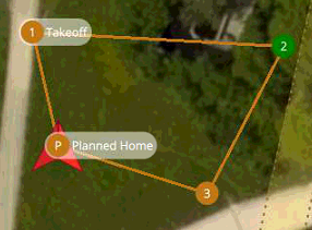


Figure 7 shows the adaptive controller variables. The bottom-most plot shows the evolution of the adaptive proportional gains and the corresponding stock PX4 fixed gains are shown in dashed lines. Note that the RCAC gains converge near the fixed gains.
Figure 8 shows the adaptive controller variables. The bottom-most plot shows the evolution of the adaptive PI gains.
Figure 9 shows the adaptive controller variables. The bottom-most plot shows the evolution of the adaptive P gains and the corresponding stock PX4 fixed gains are shown in dashed lines. Note that the RCAC gains converge near the fixed gains.

Figure 10 shows the adaptive controller variables. The bottom-most plot shows the evolution of the adaptive feedforward and the PID gains.

Next, the effect of the hypreparameters and on the performance of the adaptive PX4 autopilot is investigated. First, in all of the controllers updated by RCAC, is multiplied by , where , while all other tuning settings are held fixed. Figure 11 shows the trajectory achieved by the quadcopter for several values of . Note that quadcopter response is slower for smaller values of .

Next, in all of the controllers updated by RCAC, is multiplied by , where , while all other tuning settings are held fixed. Figure 12 shows the trajectory achieved by the quadcopter for several values of . Note that quadcopter response degrades for smaller values of .

Finally, the physical properties of the simulated quadcopter are varied to compare the performance of the stock and the adaptive PX4 controller in off-nominal conditions. In particular, the moment-of-inertia matrix of the quadcopter is scaled by a factor of five, and the stock and the adaptive PX4 controller are used to follow the trajectory shown in Figure 3 and Figure 4. Figure 13 shows yaw angle of the quadcopter during the trajectory. Note that the closed-loop yaw response with the stock PX4 controller is oscillatory, whereas the closed-loop yaw response with the adaptive PX4 controller is similar to the closed-loop yaw response obtained in the nominal condition (shown in lower-left plot in Figure 6). Figure 14 shows the adaptive PX4 controller gains in the off-nominal and the nominal condition. Note that the controller gains of evolve accordingly to maintain similar performance.

VI Conclusions and Future Work
This paper presented the implementation of adaptive PID controllers in the PX4 autopilot. In particular, the P and the PID controller in the position controller, and the P and the feedforward and PID controller in the attitude controller were replaced by adaptive controllers. The performance of the adaptive autopilot was investigated by integrating a quadcopter simulator with the autopilot. The robustness of the adaptive autopilot was investigated by varying the hyperparameters of the adaptive controller and the physical moment-of-inertial matrix of the quadcopter. In the nominal case, the adaptive PX4 controller performance similar to the stock PX4 controller However, in the off-nominal case, the closed-loop response of the quadcopter with the stock PX4 controller degraded considerably, whereas the adaptive PX4 controller adapted to maintain similar performance obtained in the nominal case.
The future work will focus on investigating the performance of the retrospective-cost based adaptive PX4 controller with forgetting factor, investigating the performance of IIR controllers in the position and attitude controllers, and conducting physical flight tests to validate the simulation results.
VII Acknowledgments
This research was supported in part by the Office of Naval Research under grant N00014-19-1-2273. The first author would like to thank S. A. U. Islam, G. Goel, P. S. Sharma, M. Romano, and G. Haggin for extremely helpful discussions about the PX4 autopilot.
References
- [1] C.-C. Chang, J.-L. Wang, C.-Y. Chang, M.-C. Liang, and M.-R. Lin, “Development of a multicopter-carried whole air sampling apparatus and its applications in environmental studies,” Chemosphere, vol. 144, pp. 484–492, 2016.
- [2] S. Anweiler and D. Piwowarski, “Multicopter platform prototype for environmental monitoring,” Journal of Cleaner Production, vol. 155, pp. 204–211, 2017.
- [3] V. H. Andaluz, E. López, D. Manobanda, F. Guamushig, F. Chicaiza, J. S. Sánchez, D. Rivas, F. Pérez, C. Sánchez, and V. Morales, “Nonlinear controller of quadcopters for agricultural monitoring,” in International Symposium on Visual Computing. Springer, 2015, pp. 476–487.
- [4] B. E. Schäfer, D. Picchi, T. Engelhardt, and D. Abel, “Multicopter unmanned aerial vehicle for automated inspection of wind turbines,” in 2016 24th Mediterranean Conference on Control and Automation (MED). IEEE, 2016, pp. 244–249.
- [5] M. Stokkeland, K. Klausen, and T. A. Johansen, “Autonomous visual navigation of unmanned aerial vehicle for wind turbine inspection,” in 2015 International Conference on Unmanned Aircraft Systems (ICUAS). IEEE, 2015, pp. 998–1007.
- [6] L. Meier, D. Honegger, and M. Pollefeys, “Px4: A node-based multithreaded open source robotics framework for deeply embedded platforms,” in 2015 IEEE international conference on robotics and automation (ICRA). IEEE, 2015, pp. 6235–6240.
- [7] Y. Rahman, A. Xie, and D. S. Bernstein, “Retrospective Cost Adaptive Control: Pole Placement, Frequency Response, and Connections with LQG Control,” IEEE Contr. Sys. Mag., vol. 37, pp. 28–69, Oct. 2017.
- [8] M. Kamaldar, S. A. U. Islam, S. Sanjeevini, A. Goel, J. B. Hoagg, and D. S. Bernstein, “Adaptive digital pid control of first-order-lag-plus-dead-time dynamics with sensor, actuator, and feedback nonlinearities,” Advanced Control for Applications, vol. 1, no. 1, p. e20, 2019, e20 adc2.0020. [Online]. Available: https://onlinelibrary.wiley.com/doi/abs/10.1002/adc2.20
- [9] E. Kayacan, M. A. Khanesar, J. Rubio-Hervas, and M. Reyhanoglu, “Learning control of fixed-wing unmanned aerial vehicles using fuzzy neural networks,” International Journal of Aerospace Engineering, vol. 2017, 2017.
- [10] A. A. Ansari, N. Zhang, and D. Bernstein, “Retrospective cost adaptive pid control of quadcopter/fixed-wing mode transition in a vtol aircraft,” in 2018 AIAA Guidance, Navigation, and Control Conference, 2018, p. 1838.