Development and application of a 3He Neutron Spin Filter at J-PARCPreprint: AIP/123-QED
Abstract
We are developing a neutron polarizer with polarized 3He gas, referred to as a 3He spin filter, based on the Spin Exchange Optical Pumping (SEOP) for polarized neutron scattering experiments at Materials and Life Science Experimental Facility (MLF) of Japan Proton Accelerator Research Complex (J-PARC). A 3He gas-filling station was constructed at J-PARC, and several 3He cells with long spin relaxation times have been fabricated using the gas-filling station. A laboratory has been prepared in the MLF beam hall for polarizing 3He cells, and compact pumping systems with laser powers of 30 W and 110 W, which can be installed onto a neutron beamline, have been developed. A 3He polarization of 85% was achieved at a neutron beamline by using the pumping system with the 110 W laser. Recently, the first user experiment utilizing the 3He spin filter was conducted, and there have been several more since then. The development and utilization of 3He spin filters at MLF of J-PARC are reported.
I Introduction
A 3He spin filter is a neutron polarization device in which polarized 3He gas is enclosed in a special glass cell that does not contain boron. 3He spin filters are widely used to polarize neutrons and analyze neutron spins in neutron scattering experiments because of its capabilities to polarize neutrons in broad energy range and cover wide solid angle Babcock et al. 2016; Dhiman et al. 2017; Chen et al. 2017; Lelievre-Berna 2007; Lee and D’Adam 2016; Beecham et al. 2011. Since 3He nuclei have a strongly spin-dependent neutron absorption cross section, neutrons passing through polarized 3He gas are polarized. 3He nuclei are polarized using laser techniques known as Spin Exchange Optical Pumping (SEOP) Bouchiat, Carver, and Varnum 1960 or Metastability Optical Pumping (MEOP) Colegrove, Schearer, and Walters 1963. In SEOP, 3He gas, N2 gas, and pure rubidium or rubidium and potassium are encapsulated within a glass cell. The Rb or Rb-K cells are heated to around 170∘C or 220∘C, respectively, to evaporate the alkali metals, and circularly polarized laser light irradiates the cell. Unpaired electrons of alkali atoms are polarized by optical pumping, and the spins of the electrons are exchanged with those of 3He nuclei by hyperfine interaction. A diode laser array with output power on the order of 100 W and a wavelength of 794.7 nm, which corresponds to the D1 absorption line of Rb, is typically employed. The 3He polarization can be improved by using Rb-K compared to the pure Rb case because of the high optical pumping efficiency of Rb-K Babcock et al. 2003. When the laser irradiation is stopped, the 3He polarization exponentially decays due to non-uniformity of the surrounding magnetic field, collisions of 3He atom with each other, and collisions of 3He atoms with impurities in the glass cell and a glass wall.
Ex-situ and in-situ methods are used for 3He spin filters with SEOP. In the ex-situ method, a 3He cell is polarized in a pumping station away from a neutron beamline, transferred in a magnetic cavity to keep the 3He polarization, and installed to a neutron beamline. Since the 3He polarization decays during a neutron experiment, the 3He cell needs to be periodically re-polarized and re-installed for long-running experiments. However, the advantage of using ex-situ method is that it can be used for a neutron beamline with limited space, and the installation of the instrument is straightforward. This is beneficial at spallation neutron sources, which generally have small experimental spaces. As there are many experiments with short measuring time at intense neutron beam facilities, those may be done without re-polarizing the 3He cell. In order to keep high 3He polarization during the experiment, a long relaxation time of 3He polarization is required, which makes details of the fabrication process of the 3He cells important.
On the other hand, in the in-situ method, the 3He cell is installed along with a laser system onto a neutron beamline. This method is suitable for longer experiments because a stable 3He polarization can be maintained for weeks. However, a larger space compared to the space required for the ex-situ method is needed, and the safety regulations involving the use of high powered lasers on a neutron beamline must be considered. For details of the technique for optically polarized 3He and its application, please see a reviewed paper Ref Gentile et al. 2017.
At MLF of J-PARC, world class intense pulsed neutron beams are provided to 23 neutron beamlines, and many neutron scattering experiments are conducted Nakajima et al. 2017. In Japan, the fundamental development of 3He polarization technique based on SEOP began in the 1990s Sato et al. 1994, and further development is still ongoing by Ino et al. at High Energy Accelerator Research Organization Ino et al. 2005; Ino et al. 2009; Ino et al. 2016; Ino et al. 2017; T.Ino 2018. An in-situ SEOP system dedicated for a polarized neutron spectrometer POLANO Nakajima et al. 2017; Kajimoto et al. 2019 at beamline No. 23 has been developed, and now under commissioning Ino et al. 2016; Ino et al. 2017. In order to promote user experiments using 3He spin filters on the other beamlines at MLF, we are carrying out the development of a 3He spin filters with both in-situ and ex-situ methods for their versatile uses on site at J-PARC. Experiments demonstrating their use have been performed on several beamlines. User experiments and fabrication of 3He cells have recently begun. In this paper, we report development and utilization of 3He spin filters at MLF of J-PARC.
II gas-filling station
As mentioned in the previous section, a clean gas-filling station and fabrication process without impurities are important for a 3He cell with long relaxation time. The first gas-filling station was constructed in 2018 at J-PARC. The schematic diagram of the gas-filling station is shown in Fig. 1. All the gas lines are wrapped with heaters for vacuum bake-out. An ultimate pressure of the gas-filling station was Pa after baking at 150∘C for a few days.

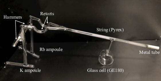
Boron-free aluminosilicate GE180 glass is widely used for the glass cell of a 3He spin filter due to a small wall relaxation effect and low permeability of 3He Jiang et al. 2013; Chen et al. 2011; Lelievre-Berna 2007; Salhi et al.. Our fabrication process of 3He cells is similar to those of NIST, JCNS, and ORNL Jiang et al. 2013; Salhi et al.; Chen et al. 2011. A cylindrical-shaped glass cell made of GE180 is attached to a glassware made of Pyrex glass, which is referred to as "string", (Fig. 2). The glass cell and the string are rinsed with neutral detergent, pure water, acetone, and alcohol before connecting to the gas-filling station. Rubidium and potassium ampoules are also rinsed with acetone and alcohol. After connecting the string to the gas-filling station, the ampoules are put in the string without breaking the ampoules, and the string is sealed off with a gas torch. The ampoules are broken in a nitrogen atmosphere by dropping hammers made of an iron rod covered with glass. The string and the glass cell are baked out for a week at 200∘C and 400∘C, respectively. In the next step, rubidium and potassium are distilled to retorts at 200∘C and 220∘C, respectively, by using the heaters. After that, the glass tube parts containing ampoules and hammers are pulled off with a gas torch. The glass cell and the string are baked out again for one week, and then the alkali metals in the retorts are distilled to the glass cell. Finally, 3He and N2 gases purified using GC50 getters (SAES Getters) are filled to the glass cell, and the glass cell is sealed off by placing a gas torch at the Pyrex part. When encapsulating the gases above 1 atm, the glass cell is submerged in liquid nitrogen to keep the pressure inside the glass cell below 1 atm while sealing. So far, nine 3He cells have been fabricated with 3He pressures of 3.1 atm using the gas-filling station at J-PARC, and four of them have found to have spin relaxation times over 150 hours. A list of these 3He cells and a photograph of Sekichiku cell are presented in Table 1 and Fig. 3, respectively.
| Name | Dimensions [mm] | 3He pressure [atm] | [h] |
|---|---|---|---|
| Chidori | 45 75 | 3.1 | 201 |
| Karigane | 45 75 | 3.1 | 180 |
| Sekichiku | 60 60 | 3.1 | 175 |
| Hanabishi | 40 90 | 3.1 | 165 |

III NMR and Pumping systems
III.1 coil and NMR system
To keep the 3He polarization, a coil with double magnetic shields, referred to as coil, is mainly used for the laser pumping Kira et al. 2013. Figure 4 shows a cross-sectional view of the coil and a photograph of its interior. The coil is consisting of a main solenoid, two compensation coils, and two side coils. The dimensions of the coil are 29.2 cm in diameter and 36.8 cm in length. The coil was designed using the finite element method to make the field gradient less than 5 /cm in a cylindrical region with a diameter of 10 cm and a length of 10 cm at the center of the coil. A magnetic field of 1.5 mT is produced to keep the 3He polarization. Frequency-sweep Adiabatic Fast Passage(AFP)-NMR was employed to flip the 3He spin as well as to evaluate the 3He polarization T.Ino 2018. A cosine winding is used as a drive coil to apply an oscillating magnetic field to the 3He cell. The 3He precession signal is detected by a pick-up coil located under the 3He cell. The coils were installed inside the coil as shown in Fig. 4. The polarization loss due to spin flip was measured as 3.810-5 per flip. The 3He cell is heated by electrical heating using a rubber heater with a power of 100 W wound around the drive coil during optical pumping.

III.2 Pumping station at MLF
We have set up a laboratory in the MLF beam hall to polarize 3He cells. 3He cells polarized at the laboratory can be provided to neutron beamlines in MLF. A pumping system using an air-cooling laser module with a laser power of 30 W Oku et al. 2015 has been installed in the laboratory (Fig. 5). The dimensions of the pumping system are 60 cm 60 cm 40 cm, and it is used for both in-situ and ex-situ methods. Using a volume Bragg grating (VBG) element in the laser module, the center wavelength of the laser is tuned to 794.7 nm with a line width of 0.2 nm in Full Width at Half Maximum (FWHM). The laser light is circularly polarized using a quarter-wavelength plate installed in the module. The polarized laser light from the laser module is reflected by dielectric multi-layer coated quartz mirrors and irradiates the 3He cell. The temperature at the cell surface is kept about 170∘C for a pure Rb cell and about 210∘C for a cell with rubidium and potassium during optical pumping. A 3He polarization of 70% is achieved with this laser system. A polarization measurement system using Electron Paramagnetic Resonance (EPR) Romalis and Cates 1998 is also equipped.

III.3 Pumping system using a fiber laser
In order to achieve higher 3He polarization, we have developed a separate pumping system using a fiber laser made by DILAS Diode Laser, Inc. (M1F4S22-794.7.[0,6]-100C-IS9), as shown in Fig. 6. The pumping system using this fiber laser has been constructed at another laboratory in the J-PARC research building, about 30 m away from the MLF experimental hall. This fiber laser is an air-cooled diode laser with a maximum output power of 110 W. The center wavelength is tuned to 794.7 nm with a line width of 0.4 nm in FWHM using a VBG element. An optical fiber with an internal diameter of 400 m is connected to the laser shield box. An unpolarized laser beam from the fiber exit is split into two paths by a polarized beam splitter. The laser beams are circularly polarized with quarter-wavelength plates. The polarized laser beams irradiate both sides of a 3He cell. The degree of circular polarization in each path was measured using a polarimeter as more than 98% at the 3He cell position. The dimensions of the pumping system are 70 cm 70 cm 40 cm, and it can also be used for the in-situ method. The pumping system is currently used only for the ex-situ method, and will be installed in the laboratory at MLF in the near future after following a safety review.

IV Performance evaluation of the 3He spin filter
We conducted an experiment at the NOBORU beamline Nakajima et al. 2017; Oikawa et al. 2008, which is a test neutron beamline for general purpose, to evaluate the 3He polarization for the Chidori cell, which has the longest as shown in Table 1. The 3He cell was polarized using the pumping system with the fiber laser at J-PARC research building. Time evolution of the 3He polarization during optical pumping is shown in Fig. 7.

After the 3He polarization was saturated, the 3He cell, the coil, and the NMR system were transferred to the NOBORU beamline in MLF while applying a magnetic field to the 3He cell using a battery to keep the 3He polarization. Neutron transmission was measured using a Gas Electron Multiplier (GEM) detector Uno et al. 2012 for the polarized and unpolarized 3He cell as well as for an empty glass cell with the same dimensions. The number of the transmitted neutrons through the 3He cell is described as Coulter et al. 1990
| (1) |
where, is the number of incident neutrons, is the transmission of the cell windows, is the detection efficiency of the GEM detector, is 3He polarization, is the number density of 3He nuclei, is the thickness of 3He gas, is the absorption cross section of the 3He nucleus for unpolarized neutrons, and is the wavelength of incident neutrons, which is calculated from the time of flight. The ratio of transmitted neutrons for the polarized to unpolarized 3He cell is described as
| (2) |
The product of the 3He gas pressure and thickness was obtained from the measurement of the ratio of transmitted neutrons for the unpolarized 3He cell to the empty glass cell as 20.80.1 atmcm. The measured ratios of are plotted againt the neutron wavelength in Fig. 8 along with the curve of best fit using Eq. (2) with as a free parameter.
The 3He polarization was measured to be 85.30.5%. The uncertainty comes mostly from the measured .
The neutron wavelength dependences on the neutron polarization is obtained using the following equation:
| (3) |
where is the polarization of neutrons passed through the polarized 3He cell, is the transmission of polarized 3He cell, and is the transmission of the unpolarized 3He cell. The transmissions and are described as
| (4) |
where is the transmitted neutrons for the empty glass cell. The neutron wavelength dependence of the neutron polarization and the neutron transmission are shown in Fig. 9. The proton beam power to the neutron source was 500 kW, and each measurement took 15 min. The relaxation time on the beamline was 170 h, which was measured with AFP-NMR.


V Trial and User Experiments using 3He spin filter
We have carried out several trial experiments with in-situ and ex-situ SEOP methods at neutron beamlines of MLF Hayashida et al. 2016; Hayashida et al. 2019; H.Kira et al. 2015; Sakai et al. 2014. In 2017, the 3He spin filter was first supplied to a user experiment. Although no user experiment was conducted in 2018, five user experiments were performed in 2019–2020. Neutron beamlines, where we conducted experiments using 3He spin filters, are listed in Table 2. In this section, we report on experiments performed on typical beamlines at MLF using 3He spin filters, including the results already reported.
| No. | Name | Purpose of beamline | Type of 3He spin filter |
|---|---|---|---|
| 04 | ANNRI | Nuclear reaction | ex-situ |
| 05 | NOP | Fundamental physics | ex-situ |
| 06 | VIN ROSE | Spin echo | ex-situ |
| 10 | NOBORU | General purpose | ex-, in-situ |
| 15 | TAIKAN | SANS | ex-, in-situ |
| 17 | SHARAKU | Reflectometer | in-situ |
| 18 | SENJU | Single crystal diffraction | ex-situ |
| 22 | RADEN | Pulsed neutron imaging | in-situ |
V.1 BL10 NOBORU
A trial experiment for magnetic imaging was carried out Hayashida et al. 2016 with in-situ and ex-situ systems using 3He cell with pure Rb and the 30 W laser as shown in Fig. 5. The in-situ system with a 3He cell of 17 atmcm and the ex-situ system with 3He cell of 11 atmcm were used as a neutron spin polarizer and analyzer, respectively. The dimensions of the 3He cells were 35 mm in diameter and 55 mm in length for both. A coil with a 0.35 mm-thick ring-shaped magnetic steel core was placed between the polarizer and the analyzer as a sample. A two-dimensional RPMT neutron detector Hirota et al. 2008 was set after the analyzer. The magnetic field applied to the sample was controlled with the current sent to the coil. Two-dimensional images of the neutron polarization were obtained, and obvious differences in the spin rotations of neutrons were observed as the wavelength dependence of the neutron polarization in two current conditions, = 1.42 A and = 0 A. Our result concluded that the magnetization patterns in these two conditions are different.
Furthermore, a study for magnetic atomic resolution holography with polarized neutrons using a 3He spin filter is currently underway. Two user experiments for this study were conducted at NOBORU in 2019–2020.
V.2 BL04 ANNRI
BL04 ANNRI Nakajima et al. 2017; Igashira, Kiyanagi, and Oshima 2009 is a neutron beamline used for studies of nuclear science such as nuclear data for nuclear technology, astrophysics, and quantitative analyses. A germanium detector assembly using 22 high-quality germanium crystals is installed on this beamline to measure the (,) reaction. Measurements of the (,) reaction for the study of fundamental symmetry violation in nuclei have been conducted as a user experiment using a 3He spin filter Yamamoto et al. 2018; Yamamoto et al. 2019; T.Yamamoto et al. 2020. A 3He spin filter with the ex-situ system was used to polarize epithermal neutrons to measure the (,) reaction with polarized neutrons at the 0.74 eV neutron resonance of 139La. A lanthanum sample was placed at the center of the germanium detector assembly, and the emitted -rays from the sample were detected by the germanium detectors. The 3He cell, solenoid, and compensation coils with a magnetic shield made of permalloy were installed between the detector and a neutron collimator (Fig. 10). The magnetic field used to keep the 3He polarization was perpendicular to the neutron beam in order to obtain a vertically polarized neutron beam. The magnetic shield had two openings in the path of the neutron beam to avoid a decay of the neutron polarization. Neutron polarization was held by the magnetic filed produced with the guide magnets to a lanthanum target. A 3He cell using pure Rb with a pressure thickness of 19.3 atmcm and dimensions of 50 mm diameter and 70 mm length was used. The 3He cell was polarized with the 30 W laser system at MLF, and the 3He polarization at the start of the measurement was typically 60%. The relaxation time of the 3He polarization was 130 h. In 2019, as a result of three separate measurements using the 3He spin filter, a significant spin-dependent angular distribution of -rays from the 0.74 eV neutron resonance of 139La was observed T.Yamamoto et al. 2020.
Furthermore, a (,) reaction measurement using polarized epithermal neutrons to obtain nuclear data for reactor science is being planned, and the development of a 3He cell for epithermal neutrons is an ongoing process.

V.3 BL17 SHARAKU
A trial experiment using the in-situ system on a beamline for neutron reflectometry: BL17 SHARAKU Nakajima et al. 2017; Takeda et al. 2012 was performed Hayashida et al. 2016. The SHARAKU beamline has a neutron polarizer and an analyzer consisting of supermirrors. Some of the supermirrors are stacked vertically in order to cover a wide area, which analyze the scattered neutron spins with wavelengths longer than 0.2 nm. However, some neutrons, which transmitted through the supermirrors are scattered by the supermirrors, and spacial distribution of neutrons reflected from a sample is disturbed. A 3He spin filter was used as the analyzer instead of the supermirrors to reduce uncertainty produced with the supermirrors (Fig. 11). The 3He cell using pure Rb with a pressure thickness of 11.1 atmcm, diameter of 35 mm, and length of 55 mm was used. A Fe-Cr multi-layered thin film was used as a sample, and off-specular measurements were performed using the in-situ system. The 3He polarization was 60% during the experiment. The in-situ system successfully demonstrated and worked stably over 4 days of the experimental time. The sample had been measured previously at ISIS, and we obtained the identical results on SHARAKU. This satisfactory implies that our in-situ system worked as designed.

V.4 BL06 VIN ROSE
BL06 VIN ROSE Nakajima et al. 2017; Hino et al. 2017 is equipped with a modulated intensity by zero effort (MIEZE) spectrometer to analyze the slow dynamics of condensed matter by measuring the intermediate scattering function. Experiments using a combination of a MIEZE spectrometer and the time of flight (TOF-MIEZE Oda et al. 2016) method have been carried out, and additionally, polarization analysis of scattered neutrons by a sample is planned in order to study spin dynamics by installing a spin analyzer. We installed a 3He cell after the sample position as an analyzer to confirm that the 3He spin filter can be used for the MIEZE spectrometer Hayashida et al. 2019. The MIEZE signal was measured with and without the 3He cell, and no difference was observed in the signal contrast. This result implies that diffusion of 3He gas does not affect the MIEZE signal and a 3He spin filter can be used as a second analyzer in the MIEZE spectrometer. Furthermore, in 2020, an experiment to measure the spin dynamics of ferrofluid was conducted by using a 3He spin filter as shown in Fig. 12. The 3He polarization of 72% and relaxation time of 120 h was achieved on this beamline in the experiment, and the analysis is currently underway.

V.5 BL15 TAIKAN
BL15 TAIKAN Nakajima et al. 2017; Shinohara et al. 2009 is a small and wide angle neutron scattering instrument. We conducted a trial experiment to measure coherent and incoherent scattering cross sections from hydrogen contained material by analyzing scattered neutrons using the in-situ system H.Kira et al. 2015. Supermirrors were installed upstream of the beamline as a neutron polarizer, and the 3He spin filter was used as a spin analyzer. Silver behenate was used as the sample, and the 3He cell with pure Rb was placed 120 mm downstream of the sample. The diameter of 3He cell was 35 mm, the length was 55 mm, and the gas pressure was 3 atm. A stable 3He polarization of 68% was kept during the experiment. Scattered neutrons reaching a part of the small-angle detector bank were spin analyzed. The coherent and incoherent scattering components were successfully separated by analyzing the scattered neutrons. Although the trial experiment was successful, the solid angle of the 3He cell was inadequate and the pressure-thickness was not suitable for the neutron wavelength used in TAIKAN. In order to cover a larger solid angle, an ex-situ SEOP system using a larger 3He cell, which is to be placed 10 mm downstream of the sample, is being prepared (Fig. 13). A new 3He cell with rubidium and potassium has been fabricated with a diameter of 60 mm, a thickness of 40 mm, and a gas pressure of 1.5 atm for cold neutrons. More trial and user experiments will be carried out in 2020.

V.6 BL21 NOVA
Experiments using 3He spin filters at BL21 NOVA Nakajima et al. 2017; Otomo et al. 2010, which is a total diffractometer, are also planned. NOVA is equipped with large solid angle neutron detectors. The detectors and a sample are installed in a large vacuum chamber. We are planning to install two ex-situ systems upstream of the beamline and around the sample to perform polarized neutron scattering experiments. The schematic view of the ex-situ systems at NOVA is shown in Fig. 14. The ex-situ system for the polarizer is installed at the upstream of the beamline, and the neutron polarization is held by the magnetic field produced with a guide coil to the sample. The scattered neutrons by the sample are analyzed with two 3He cells. This ex-situ system for the analyzer which can be installed to the vacuum chamber is developed as shown in Fig. 15. A sample is suspended from the top of the vacuum flange. The neutrons scattered by the sample are analyzed with two 3He cells placed at a distance of 20 mm from the sample. The stage for the 3He cells can be rotated so that the scattered neutrons of any angle can be analyzed. The 3He polarization is kept using the Helmholtz coil that produces 40 W of heat. The heat from the coil flows to the flange through the 30 mm thick aluminum plates connected to the coil, and the flange is air-cooled. A thermal simulation of the ex-situ system in a vacuum was performed. As a result of the simulation, the maximum temperature was determined to be 76∘C at the bottom of the coil, which does not cause a problem. A test experiment using the ex-situ system will be carried out in 2020.


VI Conclusion
Development of 3He spin filters for user experiments are being carried out at MLF at J-PARC. The in-situ system using a 30 W laser has been developed, and several trial experiments using 3He cells with pure Rb have been conducted. Recently, a gas-filling station has been constructed at J-PARC and several high quality 3He cells using rubidium and potassium were fabricated. Additionally, the pumping system using a 110 W fiber laser was developed. High 3He polarization of 85% was achieved on a neutron beamline using the 3He cell with rubidium and potassium and the pumping system using the fiber laser. The first user experiment utilizing a 3He spin filter took place in 2017, and five user experiments were conducted in 2019–2020. These experiments are beginning to yield scientific results. Preparations are underway for further user experiments using 3He spin filters.
Acknowledgement
The authors would like to thank the staff of each beamline, and MLF and J-PARC for operating the accelerators and the neutron production target. This work was supported by MEXT KAKENHI Grant Nos. 19K21047, JP19GS0210, JSPS KAKENHI Grant Nos. 18K11929, JP18H05518, and JP17H02889. The neutron scattering experiments at BL06 and BL21 were approved by the Neutron Scattering Program Advisory Committee of IMSS, KEK (Proposal Nos. 2019S06 and 2019S07). The neutron scattering experiments at BL04 were performed under the user program of MLF (Proposals Nos. 2018B0148 and 2019A0185). The neutron scattering experiments at BL10, BL15, and BL17 were performed under the program of project use (Proposal Nos. 2012P0802, 2014P0802, and 2019P0201).
References
- Babcock et al. (2016) E. Babcock, S. Zahir, T. Tobias, S.Denis, S. Johann, F. Artem, M. Stefan, P. Patrick, R. Aurel, and I. Alexander, J. Phys. Conf. Ser. 711, 012008 (2016).
- Dhiman et al. (2017) I. Dhiman, R. Ziesche, T. Wang, H. Bilheux, L. Santodonato, X. Tong, C. Y. Jiang, I. Manke, W. Treimer, T. Chatterji, and N. Kardjilov, Review of Scientific Instruments 88, 1–7 (2017).
- Chen et al. (2017) W. C. Chen, J. G. Barker, R. Jones, K. L. Krycka, S. M. Watson, C. Gagnon, T. Perevozchivoka, P. Butler, and T. R. Gentile, J. Phys. Conf. Ser. 862 (2017), 10.1088/1742-6596/862/1/012004.
- Lelievre-Berna (2007) E. Lelievre-Berna, Phys. B 397(1-2), 162–167 (2007).
- Lee and D’Adam (2016) W. T. H. Lee and T. D’Adam, Neutron News 27, 35–38 (2016).
- Beecham et al. (2011) C. J. Beecham, S. Boag, C. D. Frost, T. J. McKetterick, J. R. Stewart, K. H. Andersen, P. M. Bentley, and D. Jullien, Physica B 406, 2429–2432 (2011).
- Bouchiat, Carver, and Varnum (1960) M. Bouchiat, T. R. Carver, and C. M. Varnum, Phys. Rev. Lett. 5, 373 (1960).
- Colegrove, Schearer, and Walters (1963) F. D. Colegrove, L. D. Schearer, and G. K. Walters, Phys. Rev. 132, 2561 (1963).
- Babcock et al. (2003) E. Babcock, I. Nelson, S. Kadlecek, B. Driehuys, L. W. Anderson, F. W. Hersman, and T. G. Walker, Phys. Rev. Lett. 91, 123003 (2003).
- Gentile et al. (2017) T. R. Gentile, P. J. Nacher, B. Saam, and T. G. Walker, Rev. Mod. Phys. 89, 045004 (2017).
- Nakajima et al. (2017) K. Nakajima, Y. Kawakita, S. Itoh, J. Abe, K. Aizawa, H. Aoki, H. Endo, M. Fujita, K. Funakoshi, W. Gong, M. Harada, S. Harjo, T. Hattori, M. Hino, T. Honda, A. Hoshikawa, K. Ikeda, T. Ino, T. Ishigaki, Y. Ishikawa, H. Iwase, T. Kai, R. Kajimoto, T. Kamiyama, N. Kaneko, D. Kawana, S. O. Kawamura, T. Kawasaki, A. Kimura, R. Kiyanagi, K. Kojima, K. Kusaka, S. Lee, S. Machida, T. Masuda, K. Mishima, K. Mitamura, M. Nakamura, S. Nakamura, A. Nakao, T. Oda, T. Ohhara, K. Ohishi, H. Ohshita, K. Oikawa, T. Otomo, A. S. Furukawa, K. Shibata, T. Shinohara, K. Soyama, J. Suzuki, K. Suzuya, A. Takahara, S. Takata, M. Takeda, Y. Toh, S. Torii, N. Torikai, N. L. Yamada, T. Yamada, D. Yamazaki, T. Yokoo, M. . Yonemura, and H. Yoshizawa, Quantum Beam Sci. 1, 9 (2017).
- Sato et al. (1994) H. Sato, Y. Masuda, K. Sakai, M. Doi, K. Asahi, Z. J. Zheng, Y. Mori, P. P. J. Delheij, Y. Matsuda, M. Iinuma, H. M. Shimizu, and A. Masaike, Hyperfine Interactions 84, 205–209 (1994).
- Ino et al. (2005) T. Ino, S. Muto, Y. Masuda, G. Kim, and V. R. Skoy, Physica B 356, 109 (2005).
- Ino et al. (2009) T. Ino, M. Nakamura, T. Oku, T. Shinohara, J. Suzuki, K. Ohoyama, and H. Hiraka, Physica B 404, 2667 (2009).
- Ino et al. (2016) T. Ino, M. Ohkawara, K. Ohoyama, T. Yokoo, S. Itoh, Y. Nambu, M. Fujita, H. Kira, H. Hayashida, K. Hiroi, K. Sakai, T. Oku, and K. Kakurai, J. Phys. Conf. Ser. 711, 012011 (2016).
- Ino et al. (2017) T. Ino, K. Ohoyama, T. Yokoo, S. Itoh, M. Ohkawara, H. H. H. Kira, K. Sakai, K. Hiroi, T. Oku, K. Kakurai, and L. J. Chang, J. Phys. Conf. Ser. 862, 012011 (2017).
- T.Ino (2018) T.Ino, JPS Conf. Proc. 22, 01101 (2018).
- Kajimoto et al. (2019) R. Kajimoto, T. Yokoo, M. Nakamura, Y. Kawakita, M. Matsuura, H. Endo, H. Seto, S. Itoh, K. Nakajima, and S. Ohira-Kawamura, Physica B 562, 148–154 (2019).
- Jiang et al. (2013) C. Jiang, X. Tong, D. Brown, W. Lee, H. Ambaye, J. Craig, L. Crow, H. Culbertson, R. Goyette, M. Graves-Brook, M. Hagen, B. Kadron, V. Lauter, L. McCollum, J. Robertson, A. B. Winn, and Vandegrift, Physics Procedia 42, 191–199 (2013).
- Chen et al. (2011) W. C. Chen, T. R. Gentile, C. B. Fu, S. Watson, G. L. Jones, J. W. McIver, and D. R. Rich, J. Phys. Conf. Ser. 294, 012003 (2011).
- (21) Z. Salhi, E. Babcock, P. Pistel, and A. Ioffe, 10.1088/1742-6596/528/1/012015.
- Kira et al. (2013) H. Kira, Y. Sakaguchi, J. Suzuki, T. Oku, M. Nakamura, M. Arai, K. Kakurai, Y. Endo, Y. Arimoto, T. Ino, H. Shimizu, T. Kamiyama, K. Ohoyama, H. Hiraka, K. Tsutsumi, K. Yamada, and L.-J. Chang, Physics Procedia 42, 200 (2013).
- Oku et al. (2015) T. Oku, H. Hayashida, H. Kira, K. Sakai, K. Hiroi, T. Shinohara, Y. Sakaguchi, T. Ino, K. Ohoyama, L.-J. Chang, M. Nakamura, J. Suzuki, K. Aizawa, M. Arai, Y. Endoh, and K. Kakurai, JPS Conf. Proc. 8, 036009 (2015).
- Romalis and Cates (1998) M. V. Romalis and G. D. Cates, Phys. Rev. A 58, 3004 (1998).
- Oikawa et al. (2008) K. Oikawa, F. Maekawa, M. Harada, T. Kai, S. Meigo, Y. Kasugai, M. Ooi, K. Sakai, M. Teshigawara, S. Hasegawa, M. Futakawa, Y. Ikeda, and N. Watanabe, Nucl. Instrum. Methods Phys. Res., Sect. A 589, 310–31 (2008).
- Uno et al. (2012) S. Uno, T. Uchida, M. Sekimoto, T. Murakami, K. Miyama, M. Shoji, E. Nakano, T.Koike, K. Morita, H. Satoh, and T. andY. Kiyanagi, Physics Procedia 26, 142–152 (2012).
- Coulter et al. (1990) K. P. Coulter, T. E. Chupp, A. B. McDonald, C. D. Bowman, J. D. Bowman, J. J. Szymanski, V. Yuan, G. D. Cates, D. R. Benton, and E. D. Earle, Nucl. Instrum. Methods Phys. Res., Sect. A 288, 463–466 (1990).
- Hayashida et al. (2016) H. Hayashida, T. Oku, H. Kira, K. Sakai, K. Hiroi, T. Ino, T. Shinohara, T. Imagawa, M. Ohkawara, K. Ohoyama, K. Kakurai, M. Takeda, D. Yamazaki, K. Oikawa, M. Harada, N. Miyata, K. Akutsu, M. Mizusawa, J. D. Parker, Y. Matsumoto, S. Zhang, J. Suzuki, K. Soyama, K. Aizawa, and M. Arai, J. Phys. Conf. Ser. 711, 012007 (2016).
- Hayashida et al. (2019) H. Hayashida, M. Hino, H. Endo, T. Oku, T. Okudaira, K. Sakai, and T. Oda, J. Phys. Conf. Ser. 1316, 012013 (2019).
- H.Kira et al. (2015) H.Kira, H. Hayashida, H. Iwase, K. Ohishi, J. Suzuki, T. Oku, K. Sakai, K. Hiroi, S. Takata, T. Ino, K. Ohoyama, M. Ohkawara, T. Shinohara, K. Kakurai, K. Aizawa, and M. Arai, JPS Conf. Proc. 8, 036008 (2015).
- Sakai et al. (2014) K. Sakai, T. Oku, H. Hayashida, H. Kira, T. Shinohara, K. Oikawa, M. Harada, K. Kakurai, K. Aizawa, M. Arai, Y. Sakaguchi, J. Suzuki, T. Ino, and K. Ohoyama, J. Phys. Conf. Ser. 528, 012016 (2014).
- Hirota et al. (2008) K. Hirota, T. Shinohara, K. Ikeda, K. Mishima, T. Adachi, T. Morishima, S. Satoh, T. Oku, S. Yamada, H. Sasao, J. ichi Suzuki, and H. M. Shimizu, Phys. Chem. Chem. Phys. 7, 1836–1838 (2008).
- Igashira, Kiyanagi, and Oshima (2009) M. Igashira, Y. Kiyanagi, and M. Oshima, Nucl. Instrum. Methods Phys. Res., Sect. A 600, 332 (2009).
- Yamamoto et al. (2018) T. Yamamoto, H. M. Shimizu, M. Kitaguchi, K. Hirota, T. Okudaira, C. C. Haddock, N. Oi, I. Ito, S. Endo, S. Takada, J. Koga, T. Yoshioka, T. Ino, K. Asahi, T. Momose, T. Iwata, K. Sakai, T. Oku, A. Kimura, M. Hino, T. Shima, and Y. Yamagata, JPS Conf. Proc. 22, 011018 (2018).
- Yamamoto et al. (2019) T. Yamamoto, H. M. Shimizu, M. Kitaguchi, K. Hirota, C. C. Haddock, S. Endo, K. Ishizaki, T. Sato, S. Takada, J. Koga, T. Yoshioka, T. Ino, K. Asahi, T. Momose, T. Iwata, K. Sakai, T. Okudaira, T. Oku, A. Kimura, M. Hino, T. Shima, and Y. Yamagata, EPJ Web Conf. 219, 09002 (2019).
- T.Yamamoto et al. (2020) T.Yamamoto, T. Okudaira, S. Endo, H. Fujioka, K. Hirota, T. Ino, K. Ishizaki, A. Kimura, M. Kitaguchi, J. Koga, S. Makise, Y. Niinomi, T. Oku, K. Sakai, T. Shima, H. M. Shimizu, S. Takada, Y. Tani, H. Yoshikawa, and T. Yoshioka, arXiv , 2002.08655v1 (2020).
- Takeda et al. (2012) M. Takeda, D. Yamazaki, K. Soyama, R. Maruyama, H. Hayashida, H. Asaoka, T. Yamazaki, M. Kubota, K. Aizawa, M. Arai, Y. Inamura, T. Itoh, K. Kaneko, T. Nakamura, T. Nakatani, K. Oikawa, T. Ohara, Y. Sakaguchi, K. Sakasai, T. Shinohara, J. Suzuki, K. Suzuya, I. Tamura, K. Toh, H. Yamagishi, N. Yoshida, and T. Hirano, Chinese Journal of Physics 50, 161–170 (2012).
- Hino et al. (2017) M. Hino, T. Oda, N. L. Yamada, H. Endo, H. Seto, M. Kitaguchi, M. Harada, and Y. Kawabata, Journal of Nuclear Science and Technology 54, 1223–1232 (2017).
- Oda et al. (2016) T. Oda, M. Hino, M. Kitaguchi, P. Geltenbort, and Y. Kawabata, Review of Scientific Instruments 87, 105124 (2016).
- Shinohara et al. (2009) T. Shinohara, S. Takata, J. Suzuki, T. Oku, K. Suzuya, K. Aizawa, M. Arai, T. Otomo, and M. Sugiyama, Nucl. Instrum. Methods Phys. Res., Sect. A 600, 111 (2009).
- Otomo et al. (2010) T. Otomo, K. Suzuya, M. Misawa, N. Kaneko, H. Ohshita, K. Ikeda, M. Tsubota, T. Seya, T. Fukunaga, K. Itoh, M. Sugiyama, K. Mori, Y. Kameda, T. Yamaguchi, K. Yoshida, K. Maruyama, Y. Kawakita, S. Shamoto, K. Kodama, S. Takata, S. Satoh, S. Muto, T. Ino, H. M. Shimizu, T. Kamiyama, S. Ikeda, S. Itoh, Y. Yasu, K. Nakayoshi, H. Sendai, S. Uno, M. Tanaka, and K. Ueno, KENS Report 17, 28 (2009-2010).