MeshODE: A Robust and Scalable Framework for Mesh Deformation102CCS: Computing methodologies Shape modelingCCS: Computing methodologies Mesh geometry modelsCCS: Computing methodologies Computer graphics

Abstract.
We present MeshODE, a scalable and robust framework for pairwise CAD model deformation without prespecified correspondences. Given a pair of shapes, our framework provides a novel shape feature-preserving mapping function that continuously deforms one model to the other by minimizing fitting and rigidity losses based on the non-rigid iterative-closest-point (ICP) algorithm. We address two challenges in this problem, namely the design of a powerful deformation function and obtaining a feature-preserving CAD deformation. While traditional deformation directly optimizes for the coordinates of the mesh vertices or the vertices of a control cage, we introduce a deep bijective mapping that utilizes a flow model parameterized as a neural network. Our function has the capacity to handle complex deformations, produces deformations that are guaranteed free of self-intersections, and requires low rigidity constraining for geometry preservation, which leads to a better fitting quality compared with existing methods. It additionally enables continuous deformation between two arbitrary shapes without supervision for intermediate shapes. Furthermore, we propose a robust preprocessing pipeline for raw CAD meshes using feature-aware subdivision and a uniform graph template representation to address artifacts in raw CAD models including self-intersections, irregular triangles, topologically disconnected components, non-manifold edges, and nonuniformly distributed vertices. This facilitates a fast deformation optimization process that preserves global and local details.
On top of the methodological contributions, we create an evaluation benchmark for unsupervised pairwise shape deformation and find that our deformation results significantly outperform the state-of-the-art deformation algorithms with respect to fitting error. We show that our framework benefits various downstream applications including novel shape design and animation, scan-to-CAD fitting, and texture transfer. Our code is publicly available11 1 https://github.com/hjwdzh/MeshODE.
Keywords:
Shape Deformation, Neural Deformation1. Introduction
The Shape Deformation Problem
3D shape deformation is a fundamental problem in computer graphics and computer vision with various applications in these fields. For starters, shape deformation as a means of geometry editing can be useful for creating novel digital content by deforming a preexisting model. (Sorkine and Alexa 2007; Jiang et al. 2017) deform a source 3D model to a target shape given pairs of sparse correspondences between the source and the target to create novel shape designs. Such deformation can also be transferred to novel source shapes (Sumner and Popović 2004; Yifan et al. 2019). Moreover, shape deformation can be used for computer animation (Anguelov et al. 2005; Jacobson and Sorkine 2011) by creating smooth interpolations between key-frames. Recently, (Yifan et al. 2019; Wang et al. 2019) addressed the more challenging problem of deforming a source to an exemplar target shape without prespecified correspondences. It opens the opportunity for novel shape synthesis and animation with minimal human intervention, requiring only an exemplar target 3D model without any form of correspondence labels. Such unsupervised deformation also plays an important role in improving the fitting quality of deformed CAD models to match scanned models, which is a topic of growing interest in the vision community (Avetisyan et al. 2019a; Avetisyan et al. 2019b; Dahnert et al. 2019; Uy et al. 2020).
Challenges in shape deformation
Shape deformation is a conceptually challenging problem. A good shape deformation usually requires a good alignment of the deformed shape to the target model while preserving the shape features of the source model. The first criterion usually conflicts with the second since a perfect alignment to the target precludes the preservation of the source features. To balance the criteria, traditional methods (Sorkine and Alexa 2007; Jiang et al. 2017; Sorkine and Botsch 2009) jointly optimize for the rigidity of the source mesh and the fitting error of the correspondences specified by humans. For unsupervised shape deformation without explicit correspondences, iterative-closest-point (ICP) algorithm (Besl and McKay 1992) can be used to provide supervision for the optimization process. However, it can practically yield severe artifacts given complex CAD model structures. Recent works introduce deep learning methods to directly predict point-wise offsets (Wang et al. 2019) or to predict a control cage (Yifan et al. 2019) for more global deformations. However, direct predictions of vertex offsets do not offer sufficient regularization to the resulting shape, oftentimes leading to corrupt shape features such as self-intersections and non-physical distortions. On the other hand, predicting a coarse control cage adds too much regularization to the process, limiting the admissible degrees of freedom to allow a good fit between the deformed geometry and the target shape, leading to large fitting errors. Furthermore, these learning-based methods suffer from generalization issues and have limited capability for handling novel shapes.
Proposed formulation
We propose a novel and intuitive flow-based deformation framework that attempts to address all of the aforementioned challenges. In essence, we view the process of shape deformation as the process of convecting the geometric manifold of the source shape at time along with a temporally varying flow to time to match the target geometry. The flow can be parameterized using a neural network with trainable parameters that can be optimized via gradient descent. The deformation process can be integrated using a differentiable ODE solver (Chen et al. 2018). We use a simple geometric matching loss (the 2-way squared Chamfer Distance computed using the ICP algorithm) between the deformed shape and the target shape together with a standard rigidity loss to optimize the neural flow model.
The flow-based formulation has various inherent advantages compared with competing approaches. First, we show that any mesh deformation-induced via a sufficiently smooth and continuous flow is guaranteed to prevent the self-intersection of the original surfaces. This is crucial in limiting the space of deformations to a physical and visually appealing one since it is one of the main challenges facing models that directly predict vertex offsets or optimize for vertex positions. For example, we guarantee that front and back faces of table tops do not collide during deformation. Second, we show that the flow naturally induces a bijective mapping between the source and target geometries, which inherently guarantees the source to target to source cycle consistency for deformations, which further eases the optimization when we adopt the bidirectional fitting loss. Third, compared to a traditional parameterization of deformations using control cages or control points, the flow-based approach allows for a much higher degree of freedom for deformations due to the high representational capacity of neural networks. Last but not least, the continuous and smooth nature of the flow allows for seamless interpolation between the source and target states, allowing for smooth animations between shapes.
Mesh Preprocessing
To further extend our model to “CAD meshes in the wild" (e.g. ShapeNet (Chang et al. 2015)) that contain artifacts such as irregular triangles, non-uniform vertex distribution, non-watertight connectivity, topologically disconnected components, and self-intersections, we propose a robust computational pipeline for mitigating such irregularities, including a mesh subdivision operation, a virtual link construction, and a uniform skeleton template representation (Section 4). These steps aim to produce uniform vertex samples with geometry-aware connections for rigidity loss modeling, and thereby guarantee a fast and valid deformation optimization and preserve global and local details (e.g. geometric connectivity and sharp features). As a result, our ICP-based optimization does not have artifacts reported by (Yifan et al. 2019) and significantly outperforms the existing learning approaches based on fitting errors.
We provide a benchmark consisting of randomly selected pairs of shapes from the ShapeNet repository inside the chair, table, and sofa categories, where each pair is from the same category. We exhaustively evaluate the performance of different methods. The experiment shows that we significantly outperform the state-of-the-art according to fitting errors. We demonstrate that our framework is beneficial for many downstream applications including shape interpolation and animation, scan-to-CAD fitting, and texture reconstruction. In summary, our main contributions are:
- •
Introduction of a novel bijective flow-based deformation function with intrinsic smoothness and powerful representation capacity.
- •
Formulating a robust mesh preprocessing pipeline for dealing with complex structures of CAD models, thus enabling a practical, robust and scalable deformation framework.
- •
Evaluating deformation performance on a benchmark dataset, in which we significantly outperform the state-of-the-art.
- •
Illustration of the applicability of our framework to benefit various downstream applications including shape animation, scan-to-CAD fitting, and texture reconstruction.
2. Related Works
Mesh Deformation.
Detail-preserving deformation is an important direction in geometry processing and has been studied for decades (Sorkine and Botsch 2009). In supervised deformation, users prespecify corresponding pairs of points in the source and target shape, upon which the deformation algorithm deforms the source shape to match the target on the prescribed points using some sort of interpolation (Sorkine and Alexa 2007; Huang et al. 2008; Chao et al. 2010; Levi and Gotsman 2014). The key challenge is to ensure feature preservation by enforcing minimum distortion or rigidity. Without explicit correspondences, our deformation method optimizes the fitting and rigidity loss using correspondences from the iterative-closest-point (ICP) algorithm. Our novel neural deformation function is intrinsically smooth and does not require strong rigidity loss during optimization, which results in better fitting quality.
A different class of methods use a smooth parametric function so that the structure and the shape details are guaranteed to be preserved during the interpolation process. Such smooth functions can be implemented as the deformation of vertices on a coarse cage mesh template so that the deformation of the surface points are interpolated from the template (Ju et al. 2005; Joshi et al. 2007; Lipman et al. 2008; Thiery et al. 2012; Xian et al. 2012; Sacht et al. 2015; Calderon and Boubekeur 2017). Other methods implement such functions with coarse regular or spherical grid structures to model the deformation in the image or camera space (Zhou et al. 2013; Zhou and Koltun 2014; Huang et al. 2017). However despite successes in these methods to preserve geometric details, a deformation cage has limited degrees of freedom to describe subtle deformations. Although regular grids have more degrees of freedom, they require a strong rigidity constraint to avoid severe distortion and thus also has limited capacity for deformation. Our parametric function is a neural network-based function which has powerful representation capacity for complex deformations, while its intrinsic smoothness ensures a sufficient level of rigidity. Moreover, our deformation is a bijective mapping that enables unsupervised continuous deformations between shapes from both directions.
Recent works try to incorporate learning-based methods for shape deformation. For example, (Groueix et al. 2018; Wang et al. 2018) learns deformations of shapes based that share a common mesh template. This approach is limited by a strong assumption of common topology between the geometries that are modelled. A different set of methods model the deformation as a field stored on a 3D lattice grid (Yumer and Mitra 2016; Hanocka et al. 2018; Jack et al. 2018), where the resolution limits the capacity to accurately represent the source shapes. NeuralCage (Yifan et al. 2019) is able to preserve shape details by learning a deformation cage, but it suffers from limited representation capacity similar to the traditional cage-based deformation techniques. Finally, such deep-learning based methods are hard to generalize to shapes beyond the training set. In our proposal, the deformation function is a neural network, but we directly optimize for the parameters of the network and therefore do not suffer from generalization issues.
Neural Bijectors as Normalizing Flows
In the machine learning community, generative models are usually considered as a mapping from a prior distrution (e.g., a normal distribution) to a data distribution. Normalizing Flows (Rezende and Mohamed 2015) is proposed as a bijective map in order to effectively model a complex distribution. Bijection allows such flows to be trained by learning the mapping from the data distribution to the prior distrubition by using the maximum likelihood loss, and the inverse can be used to sample new data from the prior. Among the first proposed approaches are the planar and radial flows whose Jacobian is easy to compute. Such models lack expressivity in higher dimensions, hence autoregressive flow models are proposed to address the issues (Kingma et al. 2016; Dinh et al. 2016; Papamakarios et al. 2017). NeuralODE (Chen et al. 2018; Grathwohl et al. 2018) models the flow as an integration of velocity through the time, and allow continuous transformation between distributions. For example, PointFlow (Yang et al. 2019) develops a continuous normalizing flow based on it for shape generation. While all existing methods train the neural network to represent map a prior distribution to a target data distribution, we consider it as a bijective map with powerful presentation capacity that directly maps between two geometries in the physical space. We formulate it as a light-weight optimization problem without the need to pretrain on a large-scale dataset, thus avioding the generalization problem.
Shape Registration.
Our optimization process can be viewed as obtaining a deformation for minimizing the difference between two shapes. A similar topic called shape registration has been researched for decades to align point clouds from scans. Iterative closest point (ICP) (Besl and McKay 1992; Chen and Medioni 1992) is an algorithm employed to solve this problem. An overview of the variants of this algorithm (Rusinkiewicz and Levoy 2001; Díez et al. 2015) suggests that the key challenges are finding better correspondences and performing outlier-tolerant optimization. (Fitzgibbon 2003) minimizes the distance between samples using the Levenberg-Marquardt solver. (Mitra et al. 2004) propose to identify the closest point efficiently using the distance field for shape optimization. Our problem is more like a non-rigid ICP problem (Sumner et al. 2007; Li et al. 2008; Newcombe et al. 2015). The difference is that we are using neural ODE as a deep flexible template, and we deal with specific challenges of applying non-rigid ICP optimization for CAD models with complex geometry and topology.
Mesh Representation.
Subdivision is a common technique to upsample a coarse mesh using interpolation to obtain a more accurate geometry representation (Catmull and Clark 1978; Doo 1978; Dyn et al. 1990; Kobbelt 2000; Stam 1998). In contrast to direct interpolation, we aim to robustly upsample the mesh, preserve the original geometry, and obtain right-angle triangles with edges following principal curvatures. While quadrangulation algorithms (Jakob et al. 2015; Huang et al. 2018b) produce such mesh properties, they do not guarantee the preservation of all geometry details. Instead, we simply sample grid positions for each triangle along axes of computed orientation fields and remesh each triangle with a 2D delaunay triangulation (Lee and Schachter 1980). Since CAD models have geometrically close but topologically disconnected components, several works repair models by manifold conversion (Huang et al. 2018a; Chu et al. 2019). However, (Huang et al. 2018a) does not preserve sharp features and (Chu et al. 2019) produces unexpected shape boundaries. We do not rely on manifold topology, and simply build additional virtual links connecting close vertices to effectively model rigidity losses. To further enhance the performance, we used the uniform skeleton template as a proxy and transfer the deformation to the source mesh using a linear solver. Similar ideas are commonly used for skinning and skeletal animation (Capell et al. 2002) where linear interpolation is not favored. In our scenario, the template graph is a relatively dense approximation where a linear approximation is sufficiently accurate.
3. Overview
Figure 2 shows a schematic of the proposed deformation framework. In the pre-processing stage, we perform a subdivision and build a uniform skeleton template as a proxy. In the optimization stage, we solve for a deformation function that applies to the uniform skeleton. The optimization is guided by correspondences using the ICP algorithm with the sum of squared distances together with a rigidity loss (Sorkine and Alexa 2007) as the energy to minimize. Finally, we transfer the deformation of the skeleton template to the original CAD model by solving a linear system. We discuss the pre-processing step in section 4 and the mathematical formulation for the deformation problem in section 5. We discuss the creation of the benchmark in section 6 and evaluate our methods by comparison with the state-of-the-art methods. We further perform ablation studies to study the representation capacity using different deformation functions. Finally, we show that MeshODE benefits several downstream applications in section 7.
4. Mesh Representation
In this section, we aim at preprocessing the CAD model, so that most regions are isosceles right triangles with sufficient density to represent the deformation. Furthermore, we build virtual links and extract a uniform skeleton template as a deformation proxy for efficient optimization.
4.1. Mesh Filtering
Given a CAD model represented as a triangle mesh, we first normalize the mesh by applying a single translation and a uniform scale to all vertices so that the bounding box of the mesh is centered at and the maximum length along three axes is . Next, we remove degenerate elements by first looping over all triangles and removing degenerate ones containing zero area. Then, we merge duplicate vertices, such that the cleaned mesh is free from degenerate vertices, edges, and faces.
Denote the cleaned mesh at this step as where is a set of vertices, a set of undirected edges, and a set of triangles. Specifically, is the 3D coordinate of the -th vertex. is set of two vertex indices of the -th undirected edge in the mesh. is the set of three vertex indices of the -th triangle in the mesh.
4.2. Mesh Subdivision

The next step involves subdividing the mesh such that the length of each edge is below a user-specified threshold: . There are multiple options for subdividing and upsampling the original mesh. For example, we can repeatedly subdivide the current longest edge and adjacent triangles until all edge lengths are below . We notice that this method tends to produce very large meshes while most new triangles subdivided from an irregular triangle are still irregular, as shown in Figure 3(a). Such an issue also holds with the standard loop subdivision strategy (Stam 1998) where at each step we subdivide each triangle into four by connecting the midpoints of the three edges (Figure 3(b)). Another important thing to consider is the edge direction. Since appealing deformations are usually considered to be ones that bend along the principal curvature, novel edges created from the subdivision should ideally follow the principal curvature. Such problems can potentially be addressed by the state-of-the-art quadrangulation methods (Jakob et al. 2015; Huang et al. 2018b). However, such a remeshing process could change the original geometry and does not work well with disconnected components that exist in raw CAD models.
The key idea of our subdivision strategy is to upsample the mesh by sampling positions of a tangent lattice grid inside each triangle at the resolution of , where the lattice grid is fully determined by defining its origin as and its x-axis as the orientation field computed from (Huang et al. 2018b). In order to connect newly sampled points across different triangles sharing edges, we additionally subdivide each edge uniformly into segments such that the length of each segment is below . The number of segments can be determined as . Finally, each triangle can be remeshed by running a 2D Delaunay triangulation (Lee and Schachter 1980) algorithm to connect interior sampled grid positions and endpoints of the segments at the triangle boundary. As shown in Figure 3(c), our subdivision algorithm leads to fewer and more regular triangles. Additionally, internal edges follow principal curvatures which enable appealing bending deformations. In the following sections, we denote our subdivided mesh as .
4.3. Virtual Links

Since CAD models created by artists do not guarantee watertight connectivity, it is common that different object parts are topologically disconnected while geometrically self-intersecting (e.g. table tops and legs). As a result, deformation based merely on topological connectivities from breaks the geometry. Therefore, we need to additionally consider geometric relationships between vertices. We adopt a simple criterion that two vertices in are geometrically related if their Euclidean distance is below a threshold .However, explicitly storing such geometrical relationships for all pairs of close vertices is quite inefficient. Specifically, the number of geometrical relationships is quadratic to the number of vertices in the local region, while some of them can have a large number of vertices in the CAD models.
In our implementation, we create a sparse 3D uniform voxel grid with the resolution as in a unit cube, where each non-empty voxel contains a list of vertices inside the voxel. We loop over each non-empty voxel, collect the vertices from this voxel and its subsequent three voxels along the three axes. We run a 3D Delaunay triangulation to connect the vertices and keep the edges whose lengths are smaller than . Such a formulation ensures the number of constraints is with complexity in the local region. We collect all these edges together with as a set of virtual links . We use the virtual links for enforcing the rigidity constraints, such that the deformation guarantees local geometrical feature preservation without a requirement for watertight manifold topology.This is illustrated in the comparison between Figure 4(c) and (d). Virtual links visualized in Figure 4(f) additionally connect different table parts in addition to mesh edges, as can be seen in Figure 4(e).
4.4. Uniform Skeleton Template
It is sufficient to solve the deformation for with given constraints such that the deformed mesh can be represented as the updated vertex positions connected by the triangles . However,though the upper bound of edge lengths through the previous steps can be guaranteed, the distribution of vertices is dense and non-uniform, rendering the optimization process inefficient. Short edges can also cause numerical issues and thereby require small time steps during optimization.
Therefore, we additionally build a uniform skeleton template as a graph to approximate the original mesh graph. Again, we create a sparse 3D uniform voxel grid at the resolution of and for each voxel we collect the vertices from that belong to it. For each non-empty voxel, we create a node as the average of the vertices within. We define the set of created nodes as . For each virtual link in , we create a graph edge connecting to the corresponding node that vertices of the link belong to. Note that several virtual links correspond to the same edge in the graph template, and a single edge is kept for these links. We define the set of graph edges as . Finally, for the -th graph node , we store the set of vertex indices in the original mesh as , and define the collection of as . We denote such a uniform skeleton template as .
5. Mesh Deformation
We aim at solving for the deformation map between a pair of two meshes A and B, preprocessed via the proposed approach in Sec. 4, that includes the subdivided vertices, triangles, virtual links and skeleton template. Specifically, we denote the two meshes as and , where the skeleton templates are and .
5.1. Energy Minimization
We solve for the deformation in two steps. First, we deform the source skeleton template to the target shape by minimizing fitting and rigidity energies. Second, we solve a linear system to transfer the deformation of the skeleton template to the source mesh.
Suppose shape A is the source and B is the target, the energy is as follows:
| (1) |
The energy contains the fitting loss (Section 5.3) between the deformed skeleton template and the target mesh , and the rigidity loss (Section 5.4) of the deformed skeleton template , given the source template .
Furthermore, in the case of solving for the bijective deformation mapping between A and B such that either of them can be the source or target, we require to be a bijective mapping and propose the the two-way deformation energy to be:
| (2) |
In either scenario, we optimize to minimize the energy, and obtain the deformed skeleton and optionally . In the post processing step, we solve a linear system to apply the deformation to the original mesh (Section 5.5).
5.2. Deformation Function
The deformation function maps every point in the source shape to the deformed shape.
First, our framework can incorporate traditional methods (Sorkine and Alexa 2007) and explicitly represent as the set of sampled vertex coordinates in the deformed mesh, which we denote as , in which case the variables we are optimizing are the corresponding locations of these vertices in the deformed source skeleton, initialized as . Using the mesh preprocessing pipeline (detailed in Section 4), such an optimization process effectively preserves local geometry details for complex CAD models. However, we can only use such a functions for the A-to-B deformation problem by minimizing Equation 1, since there is no guarantee that is invertible.
To find an invertible deformation function by minimizing the energy in Equation 2, the key is to find a parameterized function which is flexible to handle complex deformation while ensuring invertibility. Neural ODE (Chen et al. 2018) satisfies both of these requirements. We first define the velocity field given a 3D location and time . The field is parameterized by a neural network architecture shown in Figure 5. Then, we create the deformation path for each source point where instant velocity at time is . maps all source points at time to deformed points at time . The mathematical definition of is shown in Equation 3, where is considered as the parameters of .
| (3) |
The inverse function can be inferred as
| (4) |
We use the implementation provided by Neural ODE (Chen et al. 2018) to integrate and obtain and in a differentiable way. This allows us to optimize the parameters in to achieve optimal deformation. In Section 7.1, we show smooth intermediate deformation results as an animation by computing at different time .
5.3. Fitting Loss
We consider the fitting loss between the deformed source shape and the target shape as the sum of the squared distances between vertices in the deformed source and the respective nearest vertex in target, which is similar to the ICP algorithm (Besl and McKay 1992). Specifically, the fitting loss between a deformed skeleton and the target mesh is defined as:
| (5) |
Since the target mesh is a fixed shape, we precompute a distance field as a uniform grid in a unit cube for fast retrieval of the nearest distance. By optimizing Equation 5, we are able to obtain the deformation such that vertices in the deformed source skeleton are well-covered by the target mesh. Since we additionally require the target mesh to be covered by the source skeleton, we define a fitting loss between the target skeleton vertices of the mesh and the deformed skeleton as:
| (6) |
Since the source skeleton vertices are changed during optimization, we rebuild a KDtree for the deformed skeleton at every optimization step for efficiently querying the nearest distance between the target and the deformed source skeleton.
5.4. Rigidity Loss
Our rigidity loss follows the definition in (Sorkine and Alexa 2007). Specifically measures the local distortions of the deformed point set from the original point set by aggregating the neighborhood information from an edge set . Since the edges are undirected, is equivalent to . The rigidity energy is defined in Equation 7.
| (7) |
In order to optimize the rigidity loss, we use a three-channel Euler angle for each vertex to represent its local rotation , and initialize it to be zero. These Euler angles are jointly optimized with the deformation function parameters.
5.5. Post processing
Once we obtain the deformation of the skeleton template, we can apply the deformation to the original mesh. First, we estimate the local rotation of the local region for each vertex as the optimized rotation of the nearest skeleton node. For , we deform vertices to to minimize the following energy:
| (8) |
The first term requires that the average of vertices in that are close to the -th skeleton node is close to the deformed node after the deformation. The second term is the rigidity loss that the deformed edge offset should be consistent with the estimated local rotation of the vertices (similar to Equation 7). Since is quadratic to , we can solve the massive number of vertices in the original CAD models efficiently with a linear solver.
5.6. Implementation details
We set for subdivision, for building virtual links, and as the resolution of the skeleton node. We set for Equation 7 when optimizing and when optimizing . We adopt weaker rigidity loss since is intrinsically smooth and easier to preserve shape features.
We solve with the efficient Levenberg-Marquardt algorithm (Moré 1978) implemented in the Ceres Solver22 2 http://ceres-solver.org. We solve parameters in with an Adam solver (Kingma and Ba 2014) implemented in PyTorch33 3 https://pytorch.org. In the next section, we evaluate the difference between all three versions and compare them with the state-of-the-art methods in a controlled experiment.
6. Evaluation
We create our benchmark dataset by randomly selecting 3625 pairs of shapes as sources and targets from ShapeNet. Our pairs are selected from the chair, the table, and the sofa categories and we guarantee that the two shapes from each pair belong to the same category. In Section 6.1, we evaluate our deformation framework and compare them with the state-of-the-art methods. We additionally do ablation studies for different mesh representations in Section 6.2 and different deformation functions in Section 6.3.
6.1. Comparison of Deformation Quality
| Chair | Table | Sofa | All | |
| Source | 6.232/6.232 | 6.580/6.580 | 4.805/4.805 | 6.155/6.155 |
| NeuralCage | 5.781/7.396 | 5.760/21.36 | 3.542/29.60 | 5.381/17.64 |
| 3DN | 3.000/7.523 | 3.325/10.843 | 2.952/9.482 | 3.489/10.44 |
| Ours-1way | 2.914/2.914 | 2.990/2.990 | 2.622/2.622 | 2.901/2.901 |
| Ours-2way | 2.053/2.053 | 2.073/2.073 | 1.990/1.990 | 2.052/2.052 |
| Ours-neural | 1.136/1.136 | 1.297/1.297 | 1.092/1.092 | 1.203/1.203 |
We compare our framework with the state-of-the-art methods based on the two-way Chamfer distance between the deformed source model and the target model The state-of-the-art methods include 3DN (Wang et al. 2019) and NeuralCage (Yifan et al. 2019). Our framework enables valid CAD deformation by optimizing Equation 1 using with traditional one-way () or two-way () squared Chamfer loss, and our newly proposed neural deformation with two-way squared Chamfer loss. They are shortened as “ours-1way”, “ours-2way” and “ours-neural” respectively. Note that all these experiments are performed under a single-direction scenario (Equation 1), while we additionally discuss bidirectional optimization (Equation 2) in Section 6.5 and utilize use it in Section 7.1.
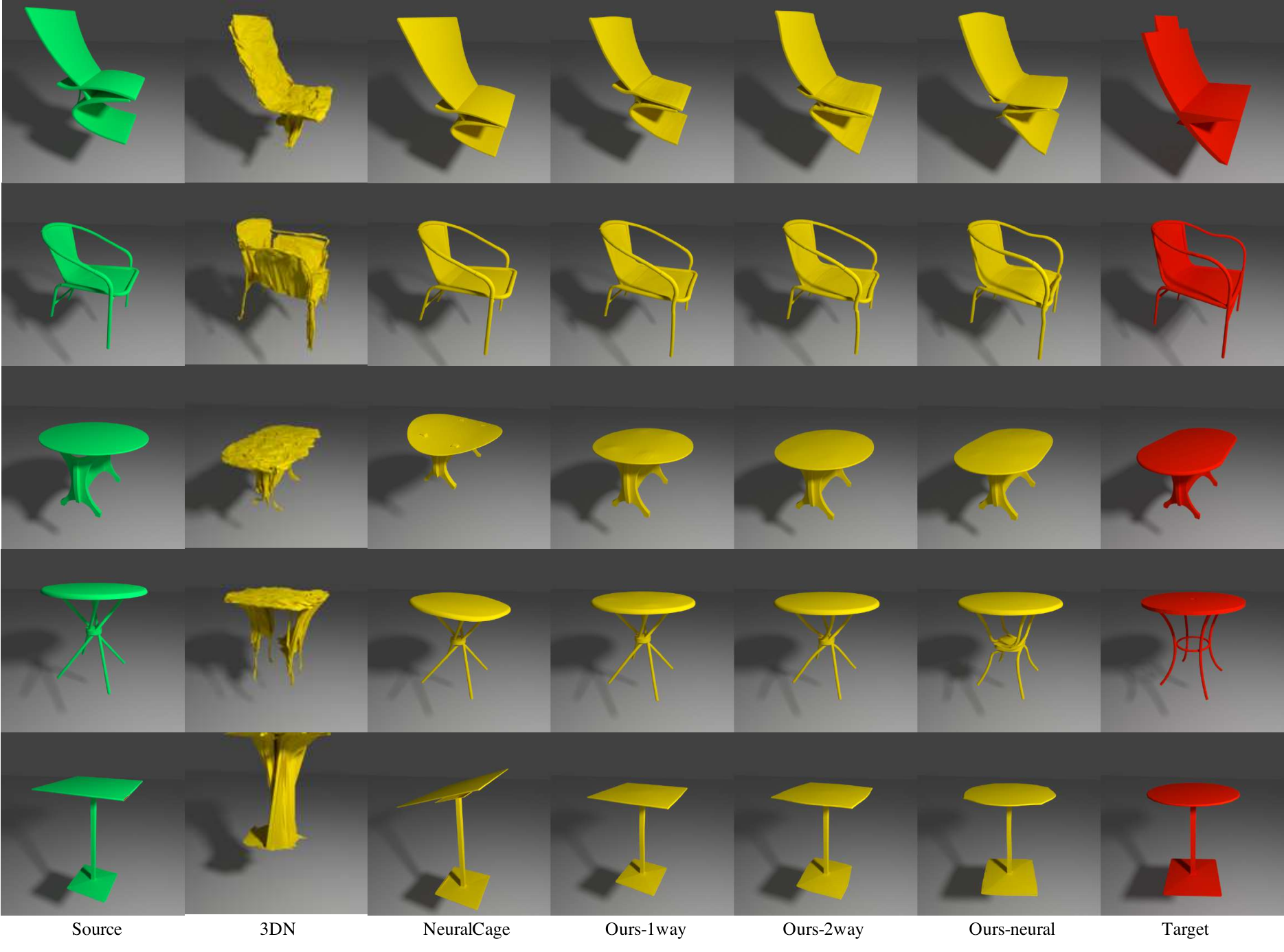
In Table 1, we report two numbers for each entry, one with the shape canonically aligned with the training data and the other with a 90-degree rotation for both the source and the target around the z-axis. All three versions of ours significantly outperform the existing state-of-the-art methods according to the fitting error. Further, the drop in performance for the deep-learning-based baselines show that they do not generalize to novel shapes or poses outside the training regime with a simple rotation variation. Visual comparisons are shown in Figure 6: Our method achieves better fitting quality and visual appeal compared to 3DN (Wang et al. 2019) and NeuralCage (Yifan et al. 2019). Ours-1way is not optimized for the coverage of the target, while ours-2way ensures coverage of both the deformed and the target shape. Ours-neural additionally provides more flexible deformation with better fitting quality. Based on the experiments, our optimization-based methods significantly outperform the existing learning-based methods with respect to the fitting errors, and our novel neural function achieves the best performance.
| NeuralCage | 3DN | Ours-1way | Ours-2way | Ours-neural |
| 1.17/4.81 | 0.58/2.12 | -/1.24 | -/3.79 | 3.73/3.96 |
Efficiency is another important factor to consider. We process all models on a server with 8 Titan X GPUs and 32 2.20GHz CPUs. The average processing time for each pair of shapes for different methods is shown in Table 2. Regarding efficiency, we find that our optimization based method: is on par with the forward pass of a trained network (NeuralCage) which relies on GPUs to do efficient computation with a big network. Our NeuralODE-based optimization uses a significantly more lightweight neural network which is easy to optimize. The gap between GPU and CPU of our NeuralODE is small, due to our reliance on a CPU implementation of Equation 1. This suggests that our GPU version has the potential to be further accelerated. Finally, we directly obtain a bijective and smooth intermediate deformation animation (Section 7.1) with infinite time resolution once our single-pass optimization is done.
6.2. Choice of Mesh Representation
| Loop | Longest | Our-CAD | Watertight | Skeleton | |
|---|---|---|---|---|---|
| Error () | 2.043 | 2.286 | 1.925 | 1.823 | 2.052 |
| Time (s) | 141.7 | 51.6 | 7.14 | 5.73 | 3.79 |

In this ablation study, we investigate the deformation performance based on different mesh representations obtained through different mesh preprocessing pipelines. We optimize Equation 1 for all variants using our proposed method and report the fitting error and timing in Table 3. Direct optimization of the original CAD model pre-processed using our subdivision method achieves the minimum fitting error. Other subdivision methods achieve slightly worse fitting quality because of the irregulararity of the triangles. Although the watertight approximation (Huang et al. 2018a) achieves good fitting to the target, the geometry is different and the sharp features can not be well-preserved, as shown in figure 7. The skeleton template representation achieves similar fitting error comparing to other subdivision methods. Efficiency-wise, deformation based on our subdivision is much faster than existing ones. Our skeleton template further improves efficiency. To balance quality and efficiency, we combine our subdivision method and the skeleton template for mesh representation.
6.3. Choice of Deformation Function
In this ablation study, we study the impacts of different choices of deformation functions on fitting errors. For traditional deformation functions, we test along with two common choices for parameterizing the deformation space, including uniform grids or control cages. We use the grids with 0.1 resolution and the convex hull of the source shape as the control cage. For learned bijective mapping, we explore the usage of several flow-based models including RealNVP (Dinh et al. 2016), MAF (Papamakarios et al. 2017), and our .
To test the representation capacity, we optimize Equation 1 for all deformation functions. Based on Figure 8, deformation grids and cages have limited representation capacity compared to . is the best choice among flow-based models and achieves better fitting quality by requiring less explicit rigidity constraints.
6.4. Part-aware Deformation

Furthermore, we explore the use of additional semantic information in our framework during pairwise shape deformations. Our inputs are pairs of chairs with semantic segmentation labels produced using PointNet (Qi et al. 2017). We separately measure the fitting loss (Section 5.3) for regions with different semantic labels and compute the sum of them as the total fitting loss. For certain semantic parts of one object that does not exist in another, we set the fitting loss as zero. In Figure 9, we show that such a modification can apply semantically meaningful deformations (e.g., chair handles are not deformed to seats).
6.5. Properties of MeshODE
We derive and evaluate several properties of MeshODE.
Bijection
If is a bijective mapping, we expect it deforms any point to a new location, while its inverse maps it back to the same point. We measure quality of bijection for a point as
| (9) |
From our numerical evaluation, the maximum and the average of for all mesh vertices in the dataset are and respectively, compared to the mesh vertex coordinate range from 0 to 1. Therefore, the numerical errors do not affect the bijectivity of our model.
Free of Self-Intersection
An intuition based illustration of proof by contradiction is given in Figure 10. Any deformation achieved through a bijective map does not induce self-interesction of any two points in the original space. This is important for dealing with thin structures (e.g. tabletop) without enforcing strong rigidity constraints.
Bidirectional Fitting
Optimization of the single-direction energy (Equation 1) targets a deformation that minimizes the distance between deformed shape A to shape B. In certain scenarios, we want to optimize for bidirectional deformation (Equation 2) so that either shape can be deformed to fit the other. In Figure 11, we evaluate the fitting loss from deformed shape A to B by plotting Equation 1 comparing two different optimizations using Equation 1 and 2. It is expected that optimization with Equation 1 achieves lower losses since the objective function is exactly the evaluation metric. However, slightly surprisingly, optimization with Equation 2 achieves a similar fitting quality, suggesting that bidirectional fitting optimization will not affect the fitting quality from either direction. This is due to the intrinsic bijection property of our deformation function.
7. Application
In this section, we demonstrate several applications that can benefit from our framework, including novel shape creation, animation, scan-to-CAD fitting, and texture reconstruction. For the shape animation and design, our ODE-based bijective function creates bidirectional deformations with smooth intermediate steps (Equation 2). For scan-to-CAD fitting and texture reconstruction, we choose to optimize for Equation 1. More results can be found in the supplemental material.
7.1. Shape Animation and Design

By optimizing the smooth deformation function , we are able to obtain a time-dependent velocity fields . We can create intermediate steps of the deformation as an animation, where and are uniformly and densely sampled in . This additionally allows the designer to interactively create new shapes by deciding how close the shape is to the target using the style of the source shape by specifying a single interpolation scalar . Examples of such a novel shape creation process are shown in figure 12, where for every two rows our input is the two shapes shown in green and red, and yellow shapes are intermediate results via deformation.
7.2. Scan-to-CAD

| Chair | Table | Sofa | All | |
| Human | 1.715 | 2.832 | 1.947 | 2.119 |
| AE | 1.856 | 2.782 | 2.142 | 2.200 |
| Uy et al. | 1.706 | 2.813 | 1.570 | 2.069 |
| (Human) | 1.343 | 1.177 | 0.845 | 1.236 |
| (AE) | 1.401 | 1.104 | 1.051 | 1.264 |
| (Uy et al.) | 1.402 | 1.173 | 1.002 | 1.283 |
By setting the scanned mesh as the target and the CAD model as the source, we can deform the CAD to fit the scan. This is a promising direction to fix the scanning geometry as explored by (Avetisyan et al. 2019a; Avetisyan et al. 2019b; Dahnert et al. 2019; Uy et al. 2020). Using our deformation that minimizes Equation 1, the CAD model can better fit the scanning geometry. In Table 4, we report the fitting error between the deformed CAD model and the scan using different retrieval methods proposed in (Uy et al. 2020) including human retrieval (Human), nearest neighbor under autoencoder (AE), the retrieval method in Uy et al.. The first three rows are use the deformation function in (Uy et al. 2020) as a baseline, and the last three are deformed using our method. As a result, our deformation produces better results with respect to the fitting error based on different retrieval methods. Figure 13 shows some visual comparisons, where we produce deformed source shapes with better fitting quality to scans.
7.3. Texture Optimization
Finally, we demonstrate that our deformation framework can help with transferring scanned textures to scanned CAD models that are aligned with the scans. This can be used for enhancing the appearance of the CAD fitting to the scans, as proposed in (Huang et al. 2020).

With good deformation, the texture is easier to optimize from observed images to the fitted CAD model, since our deformation enables better alignment and therefore less geometry alignment errors. Specifically, we optimize based on the two-way fitting (Equation 1) to deform the CAD to the scanned geometry and optimize the texture from images to the geometry according to to (Huang et al. 2020). Compared to the result from (Huang et al. 2020) without any deformation, the texture appearance on our deformed CAD model has fewer artifacts, as shown in Figure 14. Such improvement mostly happen at the corners or object boundaries, where severely misaligned regions cannot be easily address by pure texture optimization.
8. Conclusion
We develop a robust and scalable framework for CAD deformation. Our key contribution is a novel neural deformation function that enables bi-directional deformation between two shapes with continuous intermediate steps. Our mesh representation enables valid deformation with complex CAD model structures and our results significantly outperform existing state-of-the-art methods. Our deformation framework enables several applications related to shape animation and design, scanning, and texture reconstruction.
Our method can be further extended in several future directions. A multi-grid optimization could further improve the deformation in a global-local manner with better convergence. It is possible to enforce a divergence-free velocity field by applying a curl operator. This will be essential for applications that require volume-preserving deformation, e.g., human animation. Finally, it is possible to modify the velocity field of the neural function to accept additional parameters to describe deformations between multiple models and encode the models into a deformation space.
References
- (1)
- Anguelov et al. (2005) Dragomir Anguelov, Praveen Srinivasan, Daphne Koller, Sebastian Thrun, Jim Rodgers, and James Davis. 2005. SCAPE: shape completion and animation of people. In ACM SIGGRAPH 2005 Papers. 408–416.
- Avetisyan et al. (2019a) Armen Avetisyan, Manuel Dahnert, Angela Dai, Manolis Savva, Angel X Chang, and Matthias Nießner. 2019a. Scan2cad: Learning cad model alignment in rgb-d scans. In Proceedings of the IEEE Conference on Computer Vision and Pattern Recognition. 2614–2623.
- Avetisyan et al. (2019b) Armen Avetisyan, Angela Dai, and Matthias Nießner. 2019b. End-to-End CAD Model Retrieval and 9DoF Alignment in 3D Scans. In Proceedings of the IEEE International Conference on Computer Vision. 2551–2560.
- Besl and McKay (1992) Paul J Besl and Neil D McKay. 1992. Method for registration of 3-D shapes. , 586–606 pages.
- Calderon and Boubekeur (2017) Stéphane Calderon and Tamy Boubekeur. 2017. Bounding proxies for shape approximation. ACM Transactions on Graphics (TOG) 36, 4 (2017), 1–13.
- Capell et al. (2002) Steve Capell, Seth Green, Brian Curless, Tom Duchamp, and Zoran Popović. 2002. Interactive skeleton-driven dynamic deformations. ACM transactions on graphics (TOG) 21, 3 (2002), 586–593.
- Catmull and Clark (1978) Edwin Catmull and James Clark. 1978. Recursively generated B-spline surfaces on arbitrary topological meshes. Computer-aided design 10, 6 (1978), 350–355.
- Chang et al. (2015) Angel X Chang, Thomas Funkhouser, Leonidas Guibas, Pat Hanrahan, Qixing Huang, Zimo Li, Silvio Savarese, Manolis Savva, Shuran Song, Hao Su, et al. 2015. Shapenet: An information-rich 3d model repository. arXiv preprint arXiv:1512.03012 (2015).
- Chao et al. (2010) Isaac Chao, Ulrich Pinkall, Patrick Sanan, and Peter Schröder. 2010. A simple geometric model for elastic deformations. ACM transactions on graphics (TOG) 29, 4 (2010), 1–6.
- Chen et al. (2018) Tian Qi Chen, Yulia Rubanova, Jesse Bettencourt, and David K Duvenaud. 2018. Neural ordinary differential equations. In Advances in neural information processing systems. 6571–6583.
- Chen and Medioni (1992) Yang Chen and Gérard G Medioni. 1992. Object modeling by registration of multiple range images. Image Vision Comput. 10, 3 (1992), 145–155.
- Chu et al. (2019) Lei Chu, Hao Pan, Yang Liu, and Wenping Wang. 2019. Repairing man-made meshes via visual driven global optimization with minimum intrusion. ACM Transactions on Graphics (TOG) 38, 6 (2019), 158.
- Dahnert et al. (2019) Manuel Dahnert, Angela Dai, Leonidas J Guibas, and Matthias Nießner. 2019. Joint Embedding of 3D Scan and CAD Objects. In Proceedings of the IEEE International Conference on Computer Vision. 8749–8758.
- Díez et al. (2015) Yago Díez, Ferran Roure, Xavier Lladó, and Joaquim Salvi. 2015. A qualitative review on 3D coarse registration methods. ACM Computing Surveys (CSUR) 47, 3 (2015), 1–36.
- Dinh et al. (2016) Laurent Dinh, Jascha Sohl-Dickstein, and Samy Bengio. 2016. Density estimation using real nvp. arXiv preprint arXiv:1605.08803 (2016).
- Doo (1978) Daniel Doo. 1978. A subdivision algorithm for smoothing down irregularly shaped polyhederons. Computer Aided Design (1978), 157–165.
- Dyn et al. (1990) Nira Dyn, David Levine, and John A Gregory. 1990. A butterfly subdivision scheme for surface interpolation with tension control. ACM transactions on Graphics (TOG) 9, 2 (1990), 160–169.
- Fitzgibbon (2003) Andrew W Fitzgibbon. 2003. Robust registration of 2D and 3D point sets. Image and vision computing 21, 13-14 (2003), 1145–1153.
- Grathwohl et al. (2018) Will Grathwohl, Ricky TQ Chen, Jesse Bettencourt, Ilya Sutskever, and David Duvenaud. 2018. Ffjord: Free-form continuous dynamics for scalable reversible generative models. arXiv preprint arXiv:1810.01367 (2018).
- Groueix et al. (2018) Thibault Groueix, Matthew Fisher, Vladimir G Kim, Bryan C Russell, and Mathieu Aubry. 2018. 3d-coded: 3d correspondences by deep deformation. In Proceedings of the European Conference on Computer Vision (ECCV). 230–246.
- Hanocka et al. (2018) Rana Hanocka, Noa Fish, Zhenhua Wang, Raja Giryes, Shachar Fleishman, and Daniel Cohen-Or. 2018. Alignet: Partial-shape agnostic alignment via unsupervised learning. ACM Transactions on Graphics (TOG) 38, 1 (2018), 1–14.
- Huang et al. (2017) Jingwei Huang, Zhili Chen, Duygu Ceylan, and Hailin Jin. 2017. 6-DOF VR videos with a single 360-camera. In 2017 IEEE Virtual Reality (VR). IEEE, 37–44.
- Huang et al. (2018a) Jingwei Huang, Hao Su, and Leonidas Guibas. 2018a. Robust watertight manifold surface generation method for shapenet models. arXiv preprint arXiv:1802.01698 (2018).
- Huang et al. (2020) Jingwei Huang, Justus Thies, Angela Dai, Abhijit Kundu, Chiyu Max Jiang, Leonidas Guibas, Matthias Nießner, and Thomas Funkhouser. 2020. Adversarial Texture Optimization from RGB-D Scans. arXiv preprint arXiv:2003.08400 (2020).
- Huang et al. (2018b) Jingwei Huang, Yichao Zhou, Matthias Niessner, Jonathan Richard Shewchuk, and Leonidas J Guibas. 2018b. Quadriflow: A scalable and robust method for quadrangulation. In Computer Graphics Forum, Vol. 37. Wiley Online Library, 147–160.
- Huang et al. (2008) Qi-Xing Huang, Bart Adams, Martin Wicke, and Leonidas J Guibas. 2008. Non-rigid registration under isometric deformations. In Computer Graphics Forum, Vol. 27. Wiley Online Library, 1449–1457.
- Jack et al. (2018) Dominic Jack, Jhony K Pontes, Sridha Sridharan, Clinton Fookes, Sareh Shirazi, Frederic Maire, and Anders Eriksson. 2018. Learning free-form deformations for 3d object reconstruction. In Asian Conference on Computer Vision. Springer, 317–333.
- Jacobson and Sorkine (2011) Alec Jacobson and Olga Sorkine. 2011. Stretchable and twistable bones for skeletal shape deformation. In Proceedings of the 2011 SIGGRAPH Asia Conference. 1–8.
- Jakob et al. (2015) Wenzel Jakob, Marco Tarini, Daniele Panozzo, and Olga Sorkine-Hornung. 2015. Instant field-aligned meshes. ACM Trans. Graph. 34, 6 (2015), 189–1.
- Jiang et al. (2017) Tao Jiang, Kun Qian, Shuang Liu, Jing Wang, Xiaosong Yang, and Jianjun Zhang. 2017. Consistent as-similar-as-possible non-isometric surface registration. The Visual Computer 33, 6-8 (2017), 891–901.
- Joshi et al. (2007) Pushkar Joshi, Mark Meyer, Tony DeRose, Brian Green, and Tom Sanocki. 2007. Harmonic coordinates for character articulation. ACM Transactions on Graphics (TOG) 26, 3 (2007), 71–es.
- Ju et al. (2005) Tao Ju, Scott Schaefer, and Joe Warren. 2005. Mean value coordinates for closed triangular meshes. In ACM Siggraph 2005 Papers. 561–566.
- Kingma and Ba (2014) Diederik P Kingma and Jimmy Ba. 2014. Adam: A method for stochastic optimization. arXiv preprint arXiv:1412.6980 (2014).
- Kingma et al. (2016) Diederik P. Kingma, Tim Salimans, and Max Welling. 2016. Improving Variational Inference with Inverse Autoregressive Flow. CoRR abs/1606.04934 (2016). arXiv:1606.04934 http://arxiv.org/abs/1606.04934
- Kobbelt (2000) Leif Kobbelt. 2000. -subdivision. In Proceedings of the 27th annual conference on Computer graphics and interactive techniques. 103–112.
- Lee and Schachter (1980) Der-Tsai Lee and Bruce J Schachter. 1980. Two algorithms for constructing a Delaunay triangulation. International Journal of Computer & Information Sciences 9, 3 (1980), 219–242.
- Levi and Gotsman (2014) Zohar Levi and Craig Gotsman. 2014. Smooth rotation enhanced as-rigid-as-possible mesh animation. IEEE transactions on visualization and computer graphics 21, 2 (2014), 264–277.
- Li et al. (2008) Hao Li, Robert W Sumner, and Mark Pauly. 2008. Global correspondence optimization for non-rigid registration of depth scans. In Computer graphics forum, Vol. 27. Wiley Online Library, 1421–1430.
- Lipman et al. (2008) Yaron Lipman, David Levin, and Daniel Cohen-Or. 2008. Green coordinates. ACM Transactions on Graphics (TOG) 27, 3 (2008), 1–10.
- Mitra et al. (2004) Niloy J Mitra, Natasha Gelfand, Helmut Pottmann, and Leonidas Guibas. 2004. Registration of point cloud data from a geometric optimization perspective. In Proceedings of the 2004 Eurographics/ACM SIGGRAPH symposium on Geometry processing. 22–31.
- Moré (1978) Jorge J Moré. 1978. The Levenberg-Marquardt algorithm: implementation and theory. In Numerical analysis. Springer, 105–116.
- Newcombe et al. (2015) Richard A Newcombe, Dieter Fox, and Steven M Seitz. 2015. Dynamicfusion: Reconstruction and tracking of non-rigid scenes in real-time. In Proceedings of the IEEE conference on computer vision and pattern recognition. 343–352.
- Papamakarios et al. (2017) George Papamakarios, Theo Pavlakou, and Iain Murray. 2017. Masked autoregressive flow for density estimation. In Advances in Neural Information Processing Systems. 2338–2347.
- Qi et al. (2017) Charles R Qi, Hao Su, Kaichun Mo, and Leonidas J Guibas. 2017. Pointnet: Deep learning on point sets for 3d classification and segmentation. In Proceedings of the IEEE conference on computer vision and pattern recognition. 652–660.
- Rezende and Mohamed (2015) Danilo Jimenez Rezende and Shakir Mohamed. 2015. Variational inference with normalizing flows. arXiv preprint arXiv:1505.05770 (2015).
- Rusinkiewicz and Levoy (2001) Szymon Rusinkiewicz and Marc Levoy. 2001. Efficient variants of the ICP algorithm. In Proceedings Third International Conference on 3-D Digital Imaging and Modeling. IEEE, 145–152.
- Sacht et al. (2015) Leonardo Sacht, Etienne Vouga, and Alec Jacobson. 2015. Nested cages. ACM Transactions on Graphics (TOG) 34, 6 (2015), 1–14.
- Sorkine and Alexa (2007) Olga Sorkine and Marc Alexa. 2007. As-rigid-as-possible surface modeling. In Symposium on Geometry processing, Vol. 4. 109–116.
- Sorkine and Botsch (2009) Olga Sorkine and Mario Botsch. 2009. Interactive shape modeling and deformation. (2009).
- Stam (1998) Jos Stam. 1998. Evaluation of loop subdivision surfaces. In SIGGRAPH’98 CDROM Proceedings. Citeseer.
- Sumner and Popović (2004) Robert W Sumner and Jovan Popović. 2004. Deformation transfer for triangle meshes. ACM Transactions on graphics (TOG) 23, 3 (2004), 399–405.
- Sumner et al. (2007) Robert W Sumner, Johannes Schmid, and Mark Pauly. 2007. Embedded deformation for shape manipulation. In ACM SIGGRAPH 2007 papers. 80–es.
- Thiery et al. (2012) Jean-Marc Thiery, Julien Tierny, and Tamy Boubekeur. 2012. CageR: cage-based reverse engineering of animated 3D shapes. In Computer Graphics Forum, Vol. 31. Wiley Online Library, 2303–2316.
- Uy et al. (2020) Mikaela Angelina Uy, Jingwei Huang, Minhyuk Sung, Tolga Birdal, and Leonidas Guibas. 2020. Deformation-Aware 3D Model Embedding and Retrieval. arXiv preprint arXiv:2004.01228 (2020).
- Wang et al. (2018) Nanyang Wang, Yinda Zhang, Zhuwen Li, Yanwei Fu, Wei Liu, and Yu-Gang Jiang. 2018. Pixel2mesh: Generating 3d mesh models from single rgb images. In Proceedings of the European Conference on Computer Vision (ECCV). 52–67.
- Wang et al. (2019) Weiyue Wang, Duygu Ceylan, Radomir Mech, and Ulrich Neumann. 2019. 3dn: 3d deformation network. In Proceedings of the IEEE Conference on Computer Vision and Pattern Recognition. 1038–1046.
- Xian et al. (2012) Chuhua Xian, Hongwei Lin, and Shuming Gao. 2012. Automatic cage generation by improved obbs for mesh deformation. The Visual Computer 28, 1 (2012), 21–33.
- Yang et al. (2019) Guandao Yang, Xun Huang, Zekun Hao, Ming-Yu Liu, Serge Belongie, and Bharath Hariharan. 2019. Pointflow: 3d point cloud generation with continuous normalizing flows. In Proceedings of the IEEE International Conference on Computer Vision. 4541–4550.
- Yifan et al. (2019) Wang Yifan, Noam Aigerman, Vladimir Kim, Siddhartha Chaudhuri, and Olga Sorkine-Hornung. 2019. Neural Cages for Detail-Preserving 3D Deformations. arXiv preprint arXiv:1912.06395 (2019).
- Yumer and Mitra (2016) M Ersin Yumer and Niloy J Mitra. 2016. Learning semantic deformation flows with 3d convolutional networks. In European Conference on Computer Vision. Springer, 294–311.
- Zhou and Koltun (2014) Qian-Yi Zhou and Vladlen Koltun. 2014. Simultaneous localization and calibration: Self-calibration of consumer depth cameras. In Proceedings of the IEEE Conference on Computer Vision and Pattern Recognition. 454–460.
- Zhou et al. (2013) Qian-Yi Zhou, Stephen Miller, and Vladlen Koltun. 2013. Elastic fragments for dense scene reconstruction. In Proceedings of the IEEE International Conference on Computer Vision. 473–480.
Appendix
Appendix A Shape Deformation


Following Section 6.1 in the main paper, we provide additional visual comparisons on shape deformation in Figure 15 and 16. 3DN (Wang et al. 2019) and NeuralCage (Yifan et al. 2019) do not fit the target as good as our methods do. Ours-1way is not optimized for the coverage of the target, while ours-2way ensures coverage of both the deformed and the target shape. Ours-neural additionally provides more flexible deformation with better fitting quality.
Appendix B Shape Creation and Animation


Following Section 7.1 in the main paper, we provide additional examples for shape animation and design in Figure 17, 18 and 19. By optimizing the smooth deformation function , we are able to obtain a time-dependent velocity field . We can create intermediate steps of the deformation as an animation, where and are uniformly and densely sampled in . Such intermediate steps can be used for interactive novel shape design.
Appendix C Scan-to-CAD Fitting

Following Section 7.2 in the main paper, we provide additional examples for scan-to-CAD deformation fitting comparisons in Figure 20. Comparing with (Uy et al. 2020), we produce better fitting results without collapsing parts which are missing in scans.
Appendix D Texture Reconstruction

Following Section 7.3 in the main paper, we provide additional examples in Figure 21 comparing texture reconstruction using the roughly-aligned original and deformed CAD models using (Huang et al. 2020). Deformed CAD models fit scans better and leads to better texture reconstruction from aligned images.