Magnon Trap by Chiral Spin Pumping
Abstract
Chiral spin pumping is the generation of a unidirectional spin current in half of ferromagnetic films or conductors by dynamic dipolar stray fields from close-by nanomagnets. We formulate a general theory of long-range chiral interactions between magnets mediated by unidirectional traveling waves, e.g., spin waves in a magnetic film or microwaves in a waveguide. The traveling waves emitted by an excited magnet can be perfectly trapped by a second, initially passive, magnet by a dynamical interference effect. When both magnets are excited by a uniform microwave, the chiral interaction between them creates a large imbalance in their magnon numbers.
I Introduction
Unidirectional propagation of quasiparticles is a fundamental phenomenon with practical interest for information processing in logic devices [1; 2; 3; 4; 5; 6]. Magnons, the elementary excitations of the magnetic order, carry an intrinsic angular momentum that can be utilized to transport information [7; 8; 9; 10]. Dynamic dipolar stray fields emitted by ferromagnetic nanostructures can generate a unidirectional magnon current in a ferromagnetic film or conductors in its proximity by “chiral spin pumping” [11; 12; 13; 14; 15]. Magnons can propagate over centimeters [16] in magnetic insulators such as yttrium iron garnet (YIG) without Joule heating. In contrast to electrons that are easily controlled and confined by electric gates, the electric control of magnons on a small length scale is difficult. Magnons are trapped by inhomogeneous magnetic fields in, e.g., a spin-polarized atomic hydrogen gas [17] and superfluid 3He-B [18; 19]. Existing magnon transistors [20; 21] do not fully trap magnons in the film because inefficient gating.
In this work, we theoretically demonstrate trapping of waves on short length scales by the unique functionalities of chiral pumping [14; 22; 3; 4]. We first focus on a device consisting of two magnetic transducers in the form of nanowires on top of a high-quality thin film of a magnetic insulator such as YIG (Fig. 1). Exciting one of the nanomagnets by external microwaves launches spin waves in the magnetic film that propagate in one direction only [11; 12; 13; 14]. These spin waves then interact with the second nanowire that does not see the microwaves directly and excite its magnetization, which then in turn emits spin waves as well. The relative phase shift of the magnetizations in the two wires is , where is the transmission phase of the spin waves in the film. The phase shift is caused by twice the dissipative phase shift at the resonance of two identical nanowires [23]. When the spin waves from both sources interfere destructively outside the two wires, the nanowires form a magnonic cavity that confines the traveling spin waves irrespective of the geometric phase caused by their distance . The spin waves thereby cannot escape the passive wire, they are trapped. Since spin waves are not reflected back and forth to form standing waves, this mechanism is robust with respect to disorder and implies nearly perfect spin and energy transfer between the wires. The entrapment of traveling waves by the dynamic phase shift may occur in other chirally coupled systems as well: Two magnets located on a special line of a waveguide at which the momentum and rotation direction are locked [22] can trap the photons in the same manner [24].

This paper is organized as follows. We first introduce the general trapping mechanism in Sec. II and then discuss two typical cases including magnetic wires on top of a magnetic film in Sec. III and magnetic spheres in a microwave waveguide in Sec. IV. An imbalanced pumping between two magnets by chiral interaction is addressed in Sec. V. We conclude with Sec. VI.
II General trapping mechanism
Generally, we consider a chirally coupled system in one dimension, in which the magnon mode in the -th magnet of frequency at position interacts with the traveling modes of frequency , e.g., in Fig. 1 the magnon modes are the Kittel modes [25] in the nanowires and the traveling modes are spin waves in the magnetic film [11; 12; 13; 14]. Another typical example we shall highlight is two magnetic spheres in a microwave waveguide in which the magnon modes are the Kittel modes in the spheres and the traveling waves are the microwaves [22; 24; 26; 27; 28]. The model is extendable to chiral nanooptics [1] and plasmonics [3] in which the magnetic dipoles by magnon modes may be replaced by electrical dipoles [29; 30]. The chiral coupling, with mechanism addressed later, implies that the magnon modes prefer to interact with the traveling waves propagating in one direction. We use a general quantum description between harmonic oscillators that is allowed to generally describe the chirally coupled systems. We denote the coupling constant between the magnon mode and traveling waves as and the full chiral coupling indicates that one of and vanishes. The general Hamiltonian then reads [14]
| (1) |
We now consider two identical magnets located at and , which act as transducers for microwaves that are emitted or detected by local microwave antennas. They communicate by exciting and absorbing the traveling waves. Hereafter, and . Expressing the local magnon operators at and by and , we obtain the long-range chiral interaction between the two magnets mediated by the traveling waves through eliminating the dynamics of traveling modes in the equations of motion of the system [31; 32] (see Appendix A for derivation):
Here, , in which is the intrinsic damping of the Kittel modes in the magnets parameterized by the Gilbert coefficient . represent the input terms from the local antennas to the Kittel magnons, where is the additional radiative damping induced by the microwave photons that is usually much smaller than . With in mind, the couplings between magnets read
| (2) |
and the self-interaction
| (3) |
is the pumping-induced damping for a single nanowire [14]. Here, is the group velocity of the traveling waves and is the positive root of , and we have used the on-shell approximation at the ferromagnetic resonance (FMR). since , implying the (partially) chiral dissipative coupling [33; 34; 35; 36]. In the fully chiral limit with, e.g., , , i.e., twice the magnon broadening by chiral pumping Eq. (3). When one of the couplings is exactly zero, one magnet can influence the other magnet but without back action. This breaks the reciprocity of the interaction and promises new functionalities as addressed below.
We now only turn on and calculate the excited traveling waves. In frequency space and the chiral limit we have (see Appendix A)
| (4) |
where is the Green’s function of the traveling modes, where denotes the intrinsic damping of traveling modes. Equation (4) gives the phase relation between and when the left magnet is excited. At the FMR,
| (5) |
where is the positive root of , and
| (6) |
modulates the magnitude of the excited magnon amplitude. This corresponds to a phase shift
| (7) |
between the two magnets. is the phase delay by the traveling wave transmission between the two magnets. The phase shift of reflects the doubled dissipative phase shifts between magnons in the magnets and traveling waves that is the key for the magnon trap addressed below. We have recently reported observation of this phase shift with two magnetic nanowires on top of magnetic film by microwave spectroscopy [37]. Remarkably, when , , implying that the energy accumulates in the passive magnet, apparently amplifying the signal by a factor of 2.
The phase relation Eq. (5) implies the trapping of magnons at the FMR when , i.e., when the pumping-induced damping and the intrinsic damping are comparable. At the FMR, the excited traveling-wave amplitude with momentum reads
| (8) |
which indicates suppression of the right-propagating waves on the right side of the magnets when . Meanwhile, the left-propagating waves are not excited due to the nature of chiral coupling. Therefore, the excited traveling waves are confined between magnets and the magnons are trapped in the right magnet (the spatial amplitude is calculated below). By tuning one can modulate the transport of traveling waves as well.
III Magnetic nanowire and film
We consider the effectively one-dimensional model in Fig. 1 with two sufficiently long magnetic nanowires (thickness and width ) on top of a thin YIG film of thickness . The latter is of the order of tens of nanometers, such that the excited magnetization is distributed uniformly across the film without chirality itself [12; 14]. The distance between the nanowires is . Magnons in the nanowires are excited and detected by local metal stripline antennas on top of the nanowires [37]. The interlayer exchange interaction between the wire and film has been found to be smaller than the dipolar one in the antiparallel configuration [12; 13], and can be further suppressed by a spacer without affecting the longer-range dipolar coupling.
We focus on the linear regime at temperatures far below the critical one. To leading order, the magnetization operators in the magnetic wires and film may be expanded by [25; 38]
| (9) |
where and are the saturated magnetizations of film and nanowire, is the electron gyromagnetic ratio, and represent, respectively, the amplitudes of the spin waves in the film and Kittel modes in the wires, and denotes . The magnetization in the film couples to the dipolar field emitted by the magnetization of the wire via the Zeeman interaction [39; 14]. With the mode expansion, the coupling constants (refer to Appendix B.1)
| (10) |
are real and the form factor
| (11) |
is the (sufficiently large) length of the magnetic nanowire. By tuning the magnetic field to change the resonant momentum of the spin waves to the Kittel mode, the factor allows for tuning of the dipolar coupling strength. Chiral coupling is reflected by for the circularly polarized spin waves with () [14]. In the Appendix C, the full numerical simulation confirms the chiral spin pumping and validates the single-mode approximation.
We now calculate the excited magnetization in real space. By Eq. (8), at the FMR the film magnetization in Eq. (9) is the real part of
| (12) |
in which the -integral can be carried out by closing the contour in the complex plane, with singularities in the denominator of being , where is the inverse of the propagation decay length. When , the integral path is chosen in the lower half plane that selects the singularity , leading to
| (13) |
which vanishes when the chiral coupling . When , the integral path is chosen in the upper half plane that selects the singularity , and we obtain
| (14) |
which vanishes when . When ,
| (15) |
is a right-propagating wave in the chiral limit. We note that the decay of the excited magnetization is governed by the ubiquitous Gilbert damping by the complex . Without going into the details of the non-chiral system, we envision that the vanishing magnetization on the right side of the passive nanowire is also established even without chiral coupling. But the left-moving traveling waves are excited and the chiral spin pumping can even emerge in the non-chiral system with active and passive excitations by the dynamic interference effect. We note that the trapped magnetization is not a standing wave as there are no back and forth reflections. This helps to focus the magnetization to a small region of micrometers and efficiently transport the spin information directly from one wire to the other.
We illustrate the concept by calculating the pumping-induced damping and magnon trapping under chiral pumping of spin waves for Co nanowires of thickness 30 nm and width 100 nm on top of a YIG film with nm. We use the magnetizations T for YIG and T for Co [13]. The intrinsic Gilbert damping coefficient of Co wire is taken to be [13; 40; 37]. Figure 2 is the plot of the magnetic-field dependence of , the pumping-induced broadening and intrinsic one of the wire Kittel mode, which can be measured in terms of the broadening of the wire FMR. For particular magnetic fields and 139.7 mT, the pumping-induced damping equals the intrinsic one, at which the trapping becomes perfect.

In Figs. 3(a) and (b) we plot a snapshot of in real space for magnetic fields and 50 mT. We choose Co wires centered at and m. At the critical field 31.8 mT, the excited magnetization is very well confined between the two wires [(a)], while magnetization is allowed to leak into the right half-space otherwise [(b)]. This device therefore functions as a magnon valve/switch/transistor that can be opened and closed by weak magnetic fields with characteristics far superior to previous realizations that operate by very different principles [20; 21].

IV Magnetic spheres and microwave waveguide
Another example in optomagnonics is the chirally coupled magnetic spheres and microwaves in a waveguide along the direction with a rectangular cross section of dimensions (, ) [22; 26; 27; 28]. Considering the lowest TE10 mode with magnetic-field component , the magnetic field is polarization-momentum locked at the special positions termed “chiral line” with the magnetic field (details are shown in Appendix B.2). Two identical sub-mm magnetic spheres with saturation magnetization and volume are saturated in the -direction and put on the chiral lines . The diameter of the spheres is much smaller than the wavelength of the microwaves such that they can be treated as point particles [41]. The magnetization and waveguide magnetic field are quantized by (see Appendix B.2)
| (16) |
and the Zeeman coupling leads to the coupling constant
| (17) |
At the chiral line, the magnet only couples with the microwave propagating along one direction. The formalism is exactly the same as the one for magnetic wires and film. Again, with condition satisfied, excitation of the left active magnet by a local antenna can confine the microwaves between two magnets and the photon is trapped at the passive magnet: the microwaves at the right of the passive magnet
| (18) |
vanish and the microwave is unidirectionally invisible [24]. This proves that the dynamic interference effect is an universal mechanism for trapping.
V Imbalanced pumping
We turn to the situation in which the whole sample is illuminated by a global microwave field with finite and . With the same coherent driving, we may expect that chirality causes different magnon populations in the two wires. We set up the master equation of the density operator to calculate the dynamics driven by the microwaves, with frequency . In the chiral limit and at the FMR, the master equation in the rotating frame becomes [42] (refer to Appendix A for construction)
| (19) |
where represents the drive amplitude and is the Lindblad superoperator that accounts for the relaxation. Denoting the average of an operator as , the driven magnon amplitudes in the steady state become
| (20) |
where . When the excitation microwave is uniform with the same amplitude and identical magnetic nanowires with small intrinsic damping . The ratio of the steady-state magnon populations in the two magnetic nanowires
| (21) |
and hence can be on the order of ten and is tunable over a wide range by changing their separation or by the Kittel frequency. This amplification is caused by the chiral dissipative coupling between magnets, through which one magnet can input energy to another without back action. This effect can be enhanced by adding more magnets [22].
VI Discussions
In conclusion, we propose a method to control spin wave transport by weak magnetic fields based on the theory of chiral pumping of spin waves. By exploiting two nanowires that communicate by unidirectional spin waves, we achieve new functionalities such as magnon trapping, amplification and a valve/transistor effect. The spin pumping by active and passive magnets is different from conventional situation as it gives quite different behavior of pumped current. The spatial distribution of magnons can be detected inductively via microwave emission of a third magnetic wire (supposing weak disturbance on the magnonic cavity) [13], NV center magnetometry [43], Brillouin light scattering [44], and electrically by the inverse spin Hall effect with a normal metallic wire such as Pt [45]. Replacing the nanowires by other objects such as magnetic spheres or qubits, and the unidirectional spin waves by other propagating quasiparticles such as waveguide photons, surface plasmons, electrons or phonons, we envision our mechanism to be extended to other fields including optomagnonics, nanooptics [1], quantum optics, plasmonics [2; 3], spintronics, and spin mechanics.
Acknowledgements.
T. Y. and M. A. S. acknowledge funding through the DFG Emmy Noether program (SE 2558/2-1). H. W. and H. Y. are supported by NSF China under Grants No. 11674020 and No. U1801661. G.B. is supported by JSPS KAKENHI Grant No. 19H006450.Appendix A Long-range chiral interactions
In this section, we derive the long-range chiral interaction between remote magnets from the equations of motion, based on which we construct an effective non-Hermitian Hamiltonian for setting up the master equations used in the main text. From the total Hamiltonian [Eq. (1) in the main text], the equations of motion of the magnons and traveling modes read [31; 32]
| (22) |
Here, is the intrinsic damping of the Kittel modes in the magnets (e.g., the magnetic nanowire or the magnetic spheres) parameterized by the Gilbert coefficient , is the additional radiative damping induced by the microwave photons , i.e., the coupling of the magnet with the microwave antennas, and denotes the intrinsic damping of the traveling waves with momentum . Integrating the second equation in Eq. (22) yields
| (23) |
where is the input of the traveling waves that can be set to be zero without direct excitation. This leads to
| (24) |
where and we have disregarded the microwave-induced dissipative damping as usually . The third term on the r.h.s of Eq. (24) gives the effective interaction of magnons mediated by the traveling waves. The magnons are assumed to move coherently within Markov approximation, i.e., . Thus,
| (25) |
and Eq. (24) becomes
| (26) |
Here, we have defined the damping by pumping the traveling-wave ()
| (27) |
and the traveling-wave mediated effective interaction ()
| (28) |
where is the group velocity of the traveling waves and is the positive root of . In Eqs. (27) and (28), we have assumed by assuming a high quality of, e.g., magnetic film or microwave waveguide. With two identical magnets , the Heisenberg equation of motion Eq. (26) is recovered when we define the effective non-Hermitian Hamiltonian
| (29) |
The chiral dynamics is then governed by a non-Hermitian Hamiltonian, which may be separated into Hermitian and anti-Hermitian parts as
| (30) |
where . The coupling between magnons has both coherent and dissipative components. The dissipative coupling between magnons is responsible for the collective damping. The master equation used in the main text is constructed based on and .
Appendix B Chirally coupled system
B.1 Coupled magnetic wire and film
The first chirally coupled system we shall address is the dipolarly coupled magnetic nanowire and film [12; 13; 14]. We assume the nanowire magnetization is along the wire -direction, in antiparallel to the film one. The Fourier components of the dipolar field generated by a circularly polarized Kittel mode in the wire are chiral. Considering a nanowire of thickness and width , the magnetic fluctuations are the real part of
| (31) |
where is the Heaviside step function. The magnon amplitudes read [14]
| (32) |
where, by the applied magnetic field and demagnetization factors and [12],
| (33) |
The corresponding dipolar magnetic field
| (34) |
and below the nanowire () the Fourier components
A perfectly left circularly polarized wire dynamics implies that the Fourier components of with vanish. The Fourier component with is perfectly right circularly polarized . However, a pure chiral coupling still arises even with elliptically polarized Kittel mode as long as the spin waves in the film is perfectly circularly polarized (see below). We assume the magnetic film of thickness is sufficiently thin (tens of nanometer) such that the dipolar-exchange spin waves are circularly polarized. With the film magnon operator and amplitude , the film magnetization feel the dipolar field from the -th nanowire centered at via the Zeeman coupling
| (41) |
leading to the coupling Hamiltonian between the magnons and
| (42) |
with the coupling constant [14]
The Kittel mode in the nanowire couples with the spin waves with right circular polarization () propagating perpendicular to the nanowire with perfect chirality.
B.2 Coupled magnetic sphere and microwave waveguide
Another chiral system is the magnets in a microwave waveguide along the -direction [22]. Focusing on the lowest mode of a rectangular waveguide with dimensions , the magnetic fields read
| (47) |
where . The sign of the -component of the magnetic field depends on the propagation direction. Particularly, the magnetic field becomes circularly polarized when , leading to the chiral line with positions determined by
| (48) |
At the chiral line the polarization of the microwaves is locked to the momentum. The waveguide is loaded with identical YIG spheres with gyromagnetic ratio , saturation magnetization , and volume at with . The sub-mm spheres are much smaller than the photon wavelength of , so they can be treated as point particles. The static magnetic field is sufficiently strong to saturate the magnetization in the -direction. The photons and magnons are coupled by the Zeeman interaction
| (49) |
with the coupling constant
| (50) |
which depends on the position of the magnetic particles. It is chiral with one of and vanishes when the magnets are put on the chiral lines.
Appendix C Micromagnetic simulation
We carried out micromagnetic simulations by the public object-oriented micromagnetic framework (OOMMF, http://math.nist.gov/oommf) in order to justify the single-mode approximation in the magnetic nanowire and to confirm that the excited spin waves flow into one direction in half of the film. The dimensions of the YIG film is set to mm nm (). A nmm nm () Co nanowire is on the top of YIG at m. The saturation magnetizations are 1200 kA/m and 140 kA/m and the exchange constants are J/m and J/m for Co and YIG, respectively. The Gilbert damping of YIG is set to . We only include the interlayer dipolar interaction and set the interlayer exchange interaction to zero. We created antiparallel magnetization of Co and YIG by first applying a magnetic field of mT to saturate the magnetization of Co and YIG, followed by a mT field that switches only the YIG magnetization because the large shape anisotropy stabilizes the Co magnetization. We excite the magnetic nanowire by a monochromatic and uniform magnetic-field pulse that matches the mode frequency of the magnetic nanowire that depends on the width and thickness via the demagnetization factors and [12; 13; 14],
| (51) |
The resonance frequencies of the Co nanowire are extracted by a fast Fourier transform with 1000 time steps (10 ps) from the simulation. The simulated FMR frequency in Fig. 4 for isolated Co nanowires of thickness and 30 nm and widths from 100 to 400 nm agree with the above Kittel formula.

Next, we apply an oscillating field of mT with GHz to excite the FMR or a Co wire on the top of YIG with nm and nm. The spatial map of the YIG film magnetization is recorded after 1 ns as shown in Fig. 5, where the red bar indicates the Co nanowire (top view). The lineplot for the black dashed line ( from 8 to 12 m) in Fig. 5(a) is shown in Fig. 5(b). These results confirm the chiral excitation of exchange spin waves by magnetodipolar coupling between the Co nanowire and YIG film [11].
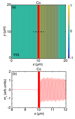
At the FMR, the excited spin waves in figure have a single wavelength that matches the frequency of the microwave pulse. This validates the single-mode approximation used in our analytical treatment. An accurate simulation of the magnon trapping by two wires cannot be done with the present set-up. It requires a large device and a constant microwave drive and an expensive effort that is beyond the scope of this work.
References
- [1] L. Novotny and B. Hecht, Principles of Nano-Optics (Cambridge University Press, Cambridge, England, 2006).
- [2] F. J. Rodríguez-Fortuño, G. Marino, P. Ginzburg, D. O’Connor, A. Martínez, G. A. Wurtz, and A. V. Zayats, Science 340, 328 (2013).
- [3] J. Petersen, J. Volz, and A. Rauschenbeutel, Science 346, 67 (2014).
- [4] T. Schneider, A. A. Serga, T. Neumann, B. Hillebrands, and M. P. Kostylev, Phys. Rev. B 77, 214411 (2008).
- [5] V. E. Demidov, M. P. Kostylev, K. Rott, P. Krzysteczko, G. Reiss, and S. O. Demokritov, Appl. Phys. Lett, 95, 2509 (2009).
- [6] T. Yu and G. E. W. Bauer, in Chirality, magnetism, and magnetoelectricity: Separate phenomena and joint effects in metamaterial structures, Edited by E. Kamenetskii (Springer, unpublished), arXiv:2001.06821.
- [7] B. Lenk, H. Ulrichs, F. Garbs, and M. Muenzenberg, Phys. Rep. 507, 107 (2011).
- [8] A. V. Chumak, V. I. Vasyuchka, A. A. Serga, and B. Hillebrands, Nat. Phys. 11, 453 (2015).
- [9] D. Grundler, Nat. Nanotech. 11, 407 (2016).
- [10] V. E. Demidov, S. Urazhdin, G. de Loubens, O. Klein, V. Cros, A. Anane, and S. O. Demokritov, Phys. Rep. 673, 1 (2017).
- [11] Y. Au, E. Ahmad, O. Dmytriiev, M. Dvornik, T. Davison, and V. V. Kruglyak, Appl. Phys. Lett. 100, 182404 (2012).
- [12] T. Yu, C. P. Liu, H. M. Yu, Y. M. Blanter, and G. E. W. Bauer, Phys. Rev. B 99, 134424 (2019).
- [13] J. L. Chen, T. Yu, C. P. Liu, T. Liu, M. Madami, K. Shen, J. Y. Zhang, S. Tu, M. S. Alam, K. Xia, M. Z. Wu, G. Gubbiotti, Y. M. Blanter, G. E. W. Bauer, and H. M. Yu, Phys. Rev. B 100, 104427 (2019).
- [14] T. Yu, Y. M. Blanter, and G. E. W. Bauer, Phys. Rev. Lett. 123, 247202 (2019).
- [15] T. Yu and G. E. W. Bauer, Phys. Rev. Lett. 124, 236801 (2020).
- [16] A. A. Serga, A. V. Chumak, and B. Hillebrands, J. Phys. D 43, 264002 (2010).
- [17] O. Vainio, J. Ahokas, J. Järvinen, L. Lehtonen, S. Novotny, S. Sheludiakov, K.-A. Suominen, S. Vasiliev, D. Zvezdov, V. V. Khmelenko, and D. M. Lee, Phys. Rev. Lett. 114, 125304 (2015).
- [18] S. Autti, Yu. M. Bunkov, V. B. Eltsov, P. J. Heikkinen, J. J. Hosio, P. Hunger, M. Krusius, and G. E. Volovik, Phys. Rev. Lett. 108, 145303 (2012).
- [19] S. Autti, V. B. Eltsov, and G. E. Volovik, Phys. Rev. Lett. 120, 215301 (2018).
- [20] A. V. Chumak, A. A. Serga, and B. Hillebrands, Nat. Comm. 5, 4700 (2014).
- [21] K. Wright, Physics 11, 23 (2018).
- [22] T. Yu, Y.-X. Zhang, S. Sharma, X. Zhang, Y. M. Blanter, and G. E. W. Bauer, Phys. Rev. Lett. 124, 107202 (2020).
- [23] Y. Au, M. Dvornik, O. Dmytriiev, and V. V. Kruglyak, Appl. Phys. Lett. 100, 172408 (2012).
- [24] Y. P. Wang, J. W. Rao, Y. Yang, P. C. Xu, Y. S. Gui, B. M. Yao, J. Q. You, and C.-M. Hu, Phys. Rev. Lett. 123, 127202 (2019).
- [25] C. Kittel, Quantum Theory of Solids (Wiley, New York, 1963).
- [26] A. G. Gurevich, Radiotekh. Elektron. (Moscow) 8, 780 (1963).
- [27] A. G. Gurevich and G. A. Melkov, Magnetization Oscillations and Waves (CRC, New York, 1996).
- [28] L. Martin, U.S. Patent No. US3426297A (1966).
- [29] K. Y. Bliokh, D. Smirnova, and F. Nori, Science 348, 1448 (2015).
- [30] K. Y. Bliokh and F. Nori, Phys. Rep. 592, 1 (2015).
- [31] C. W. Gardiner and M. J. Collett, Phys. Rev. A 31, 3761 (1985).
- [32] A. A. Clerk, M. H. Devoret, S. M. Girvin, F. Marquardt, and R. J. Schoelkopf, Rev. Mod. Phys. 82, 1155 (2010).
- [33] N. Hatano and D. R. Nelson, Phys. Rev. Lett. 77, 570 (1996).
- [34] C. M. Bender, D. C. Brody, and H. F. Jones, Phys. Rev. Lett. 89, 270401 (2002).
- [35] C. M. Bender, D. C. Brody, H. F. Jones, and B. K. Meister, Phys. Rev. Lett. 98, 040403 (2007).
- [36] Y.-P. Wang and C.-M. Hu, J. Appl. Phys. 127, 130901 (2020).
- [37] H. C. Wang, J. L. Chen, T. Yu, C. P. Liu, C. Y. Guo, H. Jia, S. Liu, K. Shen, T. Liu, J. Y. Zhang, M. A. Cabero Z, Q. M Song, S. Tu, M. Z. Wu, X. F. Han, K. Xia, D. P. Yu, G. E. W. Bauer, and H. M. Yu, arXiv:2005.10452.
- [38] T. Holstein and H. Primakoff, Phys. Rev. 58, 1098 (1940).
- [39] L. D. Landau and E. M. Lifshitz, Electrodynamics of Continuous Media, 2nd ed. (Butterworth-Heinenann, Oxford, 1984).
- [40] M. A. W. Schoen, D. Thonig, M. L. Schneider, T. J. Silva, H. T. Nembach, O. Eriksson, O. Karis, and J. M. Shaw, Nat. Phys. 12, 839 (2016).
- [41] W. C. Yu, T. Yu, and G. E. W. Bauer, arXiv:2006.02203.
- [42] C. W. Gardiner and M. J. Collett, Phys. Rev. A 31, 3761 (1985).
- [43] T. van der Sar, F. Casola, R. L. Walsworth, and A. Yacoby, Nat. Commun. 6, 7886 (2015).
- [44] S. O. Demokritov, B. Hillebrands, and A. N. Slavin, Phys. Rep. 348, 441 (2001).
- [45] L. J. Cornelissen, J. Liu, R. A. Duine, J. B. Youssef, and B. J. van Wees, Nat. Phys. 11, 1022 (2015).