Pulsed RF Schemes for Tearing Mode StabilizationPreprint: AIP/123-QED
Abstract
The RF stabilization of tearing modes with current condensation has the potential to increase stabilization efficiency and loosen power localization requirements. Such benefits stem from the cooperative feedback between the RF deposition and resulting island temperature perturbation governed by diffusion. A self consistent treatment of the damping of an rf ray as it traverses the island shows that low damping scenarios can require unfavorably high powers to overcome initial power leakage and effectively capitalize on the nonlinear effect. In this work it is demonstrated that for such regimes, modulated stabilization schemes can achieve significant improvements in heating and current drive contributions to stabilization for the same average power as a continuous wave scheme. The impact of modulation frequency and duty cycle on the performance is explored, the results of which suggest modulation strategies in which the pulsing periods are kept on the order of a diffusive time.
I Introduction
Neoclassical tearing modes (NTMs) have been identified as one of the dominant causes of disruptionsde Vries et al. 2011; de Vries et al. 2014, and are anticipated to set the primary performance limit in ITER.Haye et al. 2006; Haye, Isayama, and Maraschek 2009 Stabilization via current drive by rf wavesReiman 1983 has emerged as the leading solution, and has been the subject of much theoretical Zohm 1997; Yu and Günter 1998; Harvey and Perkins 2001; Bernabei et al. 1998; Kamendje et al. 2005; La Haye 2006; Haye et al. 2008; Sauter et al. 2010; Smolyakov et al. 2013; Ayten and and 2014; Borgogno et al. 2014; Février et al. 2016; Li et al. 2017; Grasso et al. 2018; Grasso et al. 2016 and experimental workZohm et al. 1999; Prater et al. 2003; Warrick et al. 2000; Gantenbein et al. 2000; Zohm et al. 2001; Isayama et al. 2000; La Haye et al. 2002; Petty et al. 2004; Volpe et al. 2015; Nelson et al. 2019. Prior to the treatment in Ref. Reiman and Fisch 2018, stabilization calculations were done without self-consistently considering the effect of wave deposition on island temperature. This traditional approach neglects strong nonlinear effects and the opportunities to exploit them.
The most studied waves for rf stabilization are the lower hybrid wave which drives currents through the LHCD effect Fisch 1978 and the electron cyclotron wave through the ECCD effectFisch and Boozer 1980. Although other rf waves might be enlisted to drive current Fisch 1987, these waves are highly sensitive to changes in temperature: where is the local power deposition, is the number of resonant particles and is the ratio of the phase and thermal velocities.Fisch 1987; Fisch and Boozer 1980 A small temperature perturbation then contributes an exponential enhancement factor , where , is the unpertubed temperature, and . The exponential dependence on and typically large values of translate small temperature perturbations into large effects on deposition. The thermal insulation provided by the closed magnetic topology of the island can lead to significant temperature perturbations Westerhof et al. 2007 governed by perpendicular diffusion. In combination, this amounts to a significant nonlinear enhancement of power deposited and corresponding driven current. Additionally, an initially broad deposition profile can be effectively narrowed due to the centrally peaked temperature profiles. This amplification and focusing are termed the current condensation effect, predicted in Ref. Reiman and Fisch 2018, and suggest that traditional calculations of efficiency and localization requirements have been underselling rf stabilization.
Subsequent work self consistently treating the damping of an rf ray as it traverses and heats the island Rodríguez, Reiman, and Fisch 2019 revealed two potential concerns for stabilization scenarios, hereafter referred to as leakage and shadowing. The first refers to poor absorption of the rf when the deposition width is large compared to the island width; such scenarios suffer the disadvantage of requiring high powers to effectively utilize the input energy and capitalize on the nonlinear effect. While the latter is primarily a concern in strong damping scenarios not discussed here, high enough powers can enhance deposition at the island periphery at the cost of the center for any damping strength, negatively impacting stabilization efforts.
It will be shown here that modulated schemes can unlock heating and stabilization enhancements for the same cycle averaged power as their continuous wave counterparts, when the deposition width is comparable to or larger than the island width. The effect requires a sufficiently high peak power to overcome leakage with the nonlinear effect, and is optimized for pulse periods on the order of a diffusion time which avoids shadowing. The rf capabilities of present devices are estimated to meet both the power and modulation frequency requirements for accessing this effectRodríguez, Reiman, and Fisch 2019. The requirements on relative island and deposition widths lend these results particular relevance to LHCD for steady state scenarios, where a broad deposition profile may focus within the island due to the current condensation effect. Pulsing on diffusive timescales can then further exploit the nonlinear effect to cut average power costs and minimize peripheral deposition.
The paper is organized as follows: Section II introduces the time-dependent coupled rf-island model, summarizes key features of steady state solutions motivating pulsed schemes, the time dependence of which are then explored in detail. Section III presents the heating and stabilization properties of pulsed schemes, in particular how performance may be optimized by choice of the modulation parameters, and discusses accessibility constraints. The implications of the results for developing rf stabilization strategies and their present experimental relevance are discussed in Section IV. Finally, the main conclusions are summarized in Section V.
II Coupled Wave Damping and Island Heating Model
In order to develop an intuition for the benefits of pulsed schemes, the simplest possible model that captures the physics of wave damping and island heating will be used. On the time scales of interest, the electron temperature evolution of the island interior is described by the heat diffusion equation:
| (1) |
where n is the plasma density, is the heat conductivity tensor, and is the volumetric power deposited by the rf wave, the form of which will be specified shortly. This equation can be simplified by adopting a 1-D slab model for the island geometry, treating flux surfaces isothermally, and linearizing for small perturbations of the island temperature relative to the surrounding plasma temperature :
| (2) |
subject to the boundary conditions , where is the island width. A detailed treatment of the boundary conditions and time scale orderings used to make these simplifications can be found in Ref. Rodríguez, Reiman, and Fisch 2019, with the difference here being that the present model retains time dependence on diffusive time scales–therefore the electron temperature is considered alone, neglecting the slower process of heat loss to ions. The details of this time scale ordering and its consequences can be found in Appendix B.
The power source that enters the diffusion equation is related to the wave energy density V in the following way:
| (3) |
which simply describes that the energy lost by the ray at some location goes into heating the plasma on the local flux surface. The symmetrized form results from the 1-D slab geometry, as the power deposited at a given location is shared with the whole flux surface, also labeled with .
Express the ray’s spatial damping as . The damping strength is in general a complicated function of the wave and plasma parametersBonoli and Englade 1986; Prater et al. 2008; for the purposes of studying how the wave damping couples to the island heating it can be simplified through the following reasoning. For waves acting on the tail of a Maxwellian distribution, the damping is proportional to the number of resonant particles at the wave’s phase velocity, and exponentially sensitive to small temperature perturbations:
| (4) |
where . It is important to note here that this proportionality factor is typically large for the waves of interest ( for LH and for EC), which means that small temperature perturbations can dramatically affect deposition. Therefore, this exponential enhancement factor has the strongest impact on damping strength. It can be written as an explicit factor with the weaker dependencies suppressed in the linear damping strength .
The wave damping equation then takes the form
| (5) |
with , the input energy as the wave enters the island. The equations can be further simplified by adopting the normalized temperature , and the following scalings for space, time, damping strength, and wave energy density respectively: . The quantity here may also be identified as the electron diffusion time . The final form of the coupled diffusion and wave damping equations is then:
| (6) |
| (7) |
subject to the boundary conditions (i) and (ii) . In order to expose the key effects of pulsing, we specialize to the case where the power damping is only regulated by the temperature, rather than by the magnetic field or other details of the wave trajectory. This means that for constant temperature, there is pure exponential damping and therefore the deposition will be highest at the island periphery where the power is not yet depleted. Centrally peaked deposition profiles can still be achieved with centrally peaked island temperature profiles granted by slow cross-field diffusion.
II.1 Summary of steady state solutions

Previous work with this coupled wave-island system Rodríguez, Reiman, and Fisch 2019 has been done in the steady state (, ), in which case the system is fully characterized by the two parameters and . The parameter provides a natural separation of the parameter space into a low-damping () and high-damping regime (), that are differentiated by the response of the heating efficiency with power input as illustrated in Fig. 1.
The high damping regime is characterized by monotonically decreasing heating efficiency, as even linearly the power is effectively absorbed. Increasing immediately contributes to shadowing, with rising temperatures causing the rf to be depleted ever further in the periphery. In contrast, low damping regimes have initially poor heating efficiencies due to significant energy leakage (), i.e. most of the input energy simply passes through without being absorbed by the island. With higher and correspondingly larger island temperatures, the enhanced damping improves heating efficiency until it reaches a maximum once the rf is effectively absorbed ().
At very low damping () this transition occurs suddenly, with a narrow band of powers just below this threshold where two stable solutions exist, the hotter solution corresponding to low leakage. This solution structure allows for a hysteresis effect in that after jumping to the hot solution branch, it is possible to then reduce power and stay on the hotter branch, as discussed in detail in Ref. Rodríguez, Reiman, and Fisch 2019. It is important to note that the pulsed enhancements explored in this work exist for a much broader range of and , although the physics is similar in that high powers are used to gain access to a regime with efficient absorption despite low linear damping. Increasing past this point eventually leads to diminishing gains in temperature (), as shadowing takes over.
The remainder of this paper will be confined to the low damping regime, where pulsed schemes have the opportunity to exploit the nonlinear improvement of heating efficiency with to obtain significantly improved cycle-averaged temperatures for the same average power. The eventual shadowing at high powers is relevant to understanding the optimization of pulse times, as will be elaborated in the time dependent picture.
II.2 Time evolution of heating pulse

In this work, time dependence is introduced through periodic , such that a “quasi steady state" (in the sense that system quantities (u,V) averaged over a power cycle are constant in time) is achieved. Furthermore, will always be taken to be of the form
| (8) |
where is the period of pulsing. Therefore, the island-wave system is characterized by , where is the period of pulsing, and are the cycle averaged and instantaneous powers respectively, and is the duty cycle. remains entirely unchanged from the steady state model, the cycle averaged corresponds to the steady state , while and are new degrees of freedom introduced by the pulsing.
In order to understand the impact of these modulation parameters on the performance of pulsed schemes, it is instructive to dissect the time evolution of the island-wave system as it approaches a steady state (Fig. 2). It can be seen that due to the linearly low damping and resulting initially broad deposition, diffusive edge losses are able to quickly produce a centrally peaked temperature profile that pulls the location of maximum deposition to 0. Central heating then rapidly accelerates as the absorption improves. This transient phase of the heating process exhibits highly favorable heating and stabilization properties, suggesting that an optimized pulsed scheme would require a long enough to capture its full duration.
Now examining the latter half of the heating process, as the leakage saturates to 0, the central temperature stops growing and moves back out of the center–this transition event will be termed the shadowing onset time. This shadowing occurs as the enhanced damping due to the rising island temperatures cause the incoming wave to be depleted ever further in in the periphery. Therefore, once the island is heated long enough for power to be efficiently absorbed, further heating amounts to diminishing gains in temperature and can actually reduce the current driven at the O-point. It follows that an optimum pulse time would be roughly the shadowing onset time, but shorter due to residual temperature from the previous pulse. Therefore, the optimum pulse time is set by heating with a sufficiently high instantaneous , long enough to overcome leakage, but not so long that unfavorable shadowed deposition occurs. The off time between pulses plays a more indirect role through setting for a given time averaged power and by determining how much residual temperature there is at the start of the next cycle.
III Pulsed Stabilization Schemes
III.1 Optimizing performance with pulse frequency
The merit of a pulsed scheme can be judged from the resulting temperature and current profiles. Large temperature enhancements can be understood to be favorable even in the absence of rf current drive, from the resulting perturbations to the Spitzer conductivity (from ).Kurita et al. 1994; Hegna and Callen 1997; Lazzari and Westerhof 2009 The benefits only get more dramatic once considering the exponential enhancement factor carried by the driven current (). Stabilization efforts therefore benefit from centrally peaked, large amplitude temperature profiles, qualities which are reflected in the summary measure of heating efficiency . This metric suffers from either poor absorption or broad temperature profiles resulting from shadowed deposition.
The stabilizing power of the deposition profiles can also be captured in the metric , which gives the fraction of power deposited in the center half of the island to the total power that is available to the island. While a more direct calculation based on the modified Rutherford equation as described in Ref. Rodriguez, Reiman, and Fisch 2020 is also possible, provides a more sensitive metric for studying the impact of modulation parameters on performance, and is more useful for this work. Further discussion of how the figures of merit used here compare to the traditional stability metric can be found in Appendix A.
The reasoning developed in the previous section anticipates an optimum pulse period on the order of a diffusive time, in order to reap the benefits of the transient heating period but avoid the shadowed steady state behavior. Figure 3 demonstrates this for the (, , ) case. Intuitively, the limit corresponds to the steady state, as diffusion has no time to act in between pulses, so the model here smooths out to the steady state solution for . As the system approaches the steady state solution for weighted by the duty cycle, but in this limit, other physics not included in this model will need to be accounted for. Both figures of merit improve with increasing until reaching an optimum around , corresponding to a heating time . Evidently the central temperature and central power deposition improve rapidly with increasing pulse time, as the system is given more time to be in the favorable central heating stage (early portion of Fig. 2). As the pulse times are further increased, and the system is allowed more time in the shadowed saturation period (latter portion of Fig 2), strongly reflects this suboptimality while the central temperature is not as dramatically affected. Nevertheless, as both metrics are roughly simultaneously maximized, it makes sense to speak of a unique optimal pulsing time . Figure 4 shows the optimally pulsed cycle-averaged temperature and current profiles compared to their continuous wave counterparts.


As either damping strength or power is increased (at fixed duty cycle ), the optimal pulsing time decreases as seen in Fig. 5. This is due to higher corresponding to better linear absorption, so shorter nonlinear heating time necessary to overcome leakage. Higher powers similarly require less heating time to accomplish the amount of edge temperature increase for the onset of shadowing. There is also less to be gained from optimally pulsing for either comparison case (at higher or ), which can be understood in the same framework of using pulsing to overcome leakage. If leakage is less of a concern to begin with, as would be the case for higher or , there is simply not as much room for improvement. It can also be seen that pulsing only negatively impacts performance relative to the steady state at pulse times much longer than diffusion times. This is due to the shadowed deposition associated with higher powers occupying greater portions of the heating pulse.
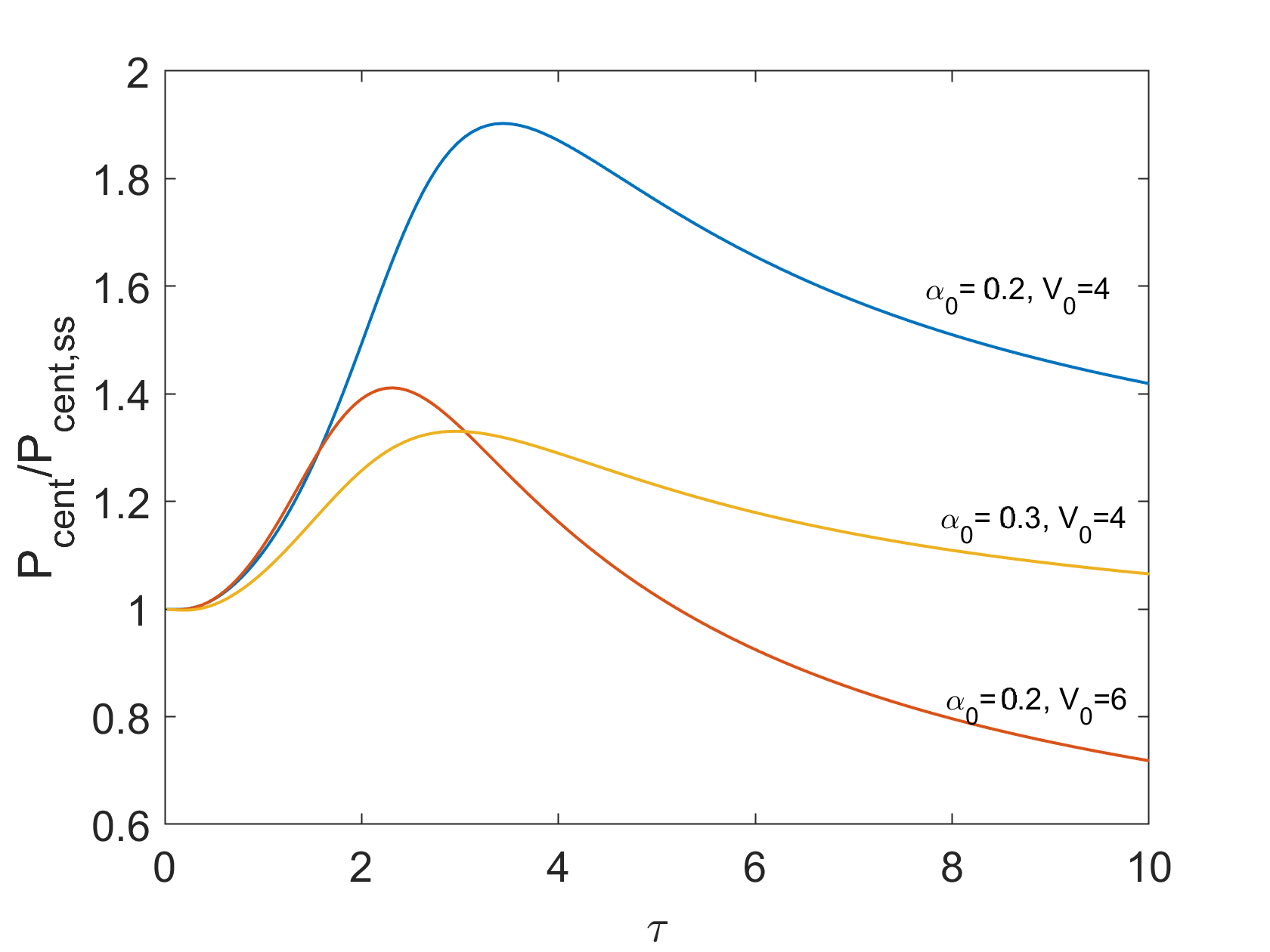
III.2 Accessibility Caveats
As suggested by the weaker improvements for increased and , the pulsed enhancements described in this work are only available for certain regions of the (,) parameter space. Although it has already been mentioned that this effect is limited to the low damping regime, there is the further simultaneous requirement that is not so high that leakage is not a concern. This decreases with increasing , as shown in Fig. 6.

There are also similarly understood accessibility requirements on the duty cycle , in that a high enough instantaneous power must be used to access a region of space without leakage. Although some improvement will be seen, as any additional power still goes towards mitigating leakage, the full potential of the effect will not be realized and there will be no optimum pulsing frequency. For the narrow band of instantaneous powers that are high enough to just barely overcome leakage but not encounter shadowing, there is a strong performance enhancement from pulsing, but no optimum pulsing frequency. For these cases, performance monotonically improves with pulse times as the instantaneous parameters correspond to a highly favorable steady state, but then additional physics must be taken into account such as heat loss to ions. Examples of such non-optimizable cases are shown for the case in Fig. 7. The accessibility requirements on mentioned here are feasible for present devices, for which . Rodríguez, Reiman, and Fisch 2019

IV Discussion
It has been demonstrated that pulsed rf stabilization schemes can achieve significantly improved heating and stabilization compared to steady-state schemes of equivalent average power, in regimes where the deposition width is large relative to the island size. The improvement is optimized when the pulsing time is on the order of the heat diffusion time. This effect can be understood as using higher instantaneous powers to achieve sufficient heating for nonlinear deposition enhancement to overcome the power leakage that would be present in the equivalent steady state. As the heating is nonlinearly enhanced while cooling remains a slow linear process, significantly higher cycle averaged temperatures and stabilizing current can be achieved for the same steady state power. The centralized heating and current profiles despite peripheral rf entry are only made possible by the diffusive nature of the island–pulsing on this natural time scale allows for active exploitation of this property.
The caveats for the accessibility of the pulsed enhancements suggest that the effect explored here would have particular utility for LHCD, where the deposition profiles tend to be broader than those for ECCD. Such broad deposition profiles are desirable for the operation of a tokamak in steady state. In that scenario, the deposition may be locally enhanced in any islands that appear via the current condensation effect, providing automatic stabilization without controlled aiming of ray trajectories. Pulsing on typical island diffusive time scales may then be employed to improve power efficiency. Additionally, it was shown that high enough powers are required to overcome leakage, but carry a risk of shadowing. Considering such parameter sensitivity and generally high uncertainty of such parameters, the results suggest that in practice it may be best keep safely under a diffusion time, rather than aiming for the theoretical optimum. It must also be noted that a highly simplified model has been used here, and as such provides insights
The trends predicted here for how the optimum pulsing frequency should depend on plasma and island parameters invite experimental verification. As the modulation frequency is swept from above diffusive time scales (> a few kHz, well within the reach of present devices) to below ( 10 Hz), the cycle averaged island temperature should increase from the steady state until a maximum and then decrease, eventually heating less effectively than the equivalent steady state only when the frequencies fall below the order of diffusive time scales. This suggests that it will be safer to overshoot the pulsing frequency, as it may be difficult in practice to determine the precise optimum pulsing frequency. Fortunately, this effect is not sensitive to establishing a precise resonance. The performance deteriorates significantly only on the slower half of frequency space. This highlights the robustness with respect to frequency of the pulsing strategies as described here. In contrast, present modulation strategies for stabilizing rotating islands rely on precise matching of island rotation rates and phasing.
In present devices, typical diffusion times correspond to frequencies of 1kHz, coincidentally right around the natural island rotation rates to which pulse times are matched. The majority of modulation experiments report modest improvements, with stabilization made possible at lower average powers compared to continuous wave schemes Maraschek et al. 2007; Volpe et al. 2009; Westerhof et al. 2007; Isayama et al. 2009; Kasparek et al. 2016. It has also been found that modulation seems to provide more a benefit when deposition is broad Maraschek et al. 2007; Zohm et al. 2007. These results have been interpreted thus far as consequences of having the deposition better coincide with the O-point, but it is possible that the effects described here may have contributed to such success. Existing experiments only allow for speculation as to how large of a role the nonlinear effect has been playing. To resolve this ambiguity, an ideal experiment for testing this diffusion based modulation method would be using resonant magnetic perturbations (RMPs) to ensure O-point deposition, while sweeping the modulation frequency and duty cycle for a fixed average power to allow direct comparison to the corresponding continuous wave scheme. The anticipated experimental signature would be clear–island temperature increasing with pulse times until an optimum is observed.
While the full treatment of ion temperature is left for future work, the limiting cases presented in appendix B motivate the investigation of pulsing as a means of limiting parasitic heat loss to the ions. When electrons and ions fully share the input power, the effective is reduced by a factor of . Considering that only the electron temperature contributes to the nonlinear effect for the waves considered here, this amounts to a considerable loss in stabilization capability for a given amount of input power. Additional inhibition mechanisms such as stiffnessRodriguez, Reiman, and Fisch 2020, triggered by ion temperature gradients, further motivate this line of inquiry.
The potential for pulsed rf schemes in the high damping regime is also left for future work. The high damping regime is characterized by flat-topped temperature profiles and is prone to shadowing– even at low powers, any additional power input only contributes to even more peripheral deposition, damaging stabilization efforts. The potential for exploiting diffusion in an arguably more direct way with a “cooling-based" method, can be understood as follows. Given a flat-topped shadowed temperature profile, upon cessation of heating, temperature will be lost rapidly from the periphery but slowly in the center, creating a more favorable damping landscape for a ray entering after this cooling period. Such an effect is present but offset by sensitivity to shadowing in this 1-D slab model, but could become dominant with a more accurate treatment of island geometry. It is further anticipated that multiple rays (with different ) may be synergistic and especially successful in this high damping regime, a possibility also left for future work.
V Summary
Pulsing rf power on diffusive time scales has the potential to achieve significantly improved heating and stabilization of magnetic islands for the same cycle-averaged power. This has been explicitly demonstrated using a simple 1-D coupled wave damping- island temperature diffusion model in the low damping regime, marked by poor linear absorption. Such pulsed schemes exploit nonlinear heating and the diffusive nature of the island temperature to overcome power leakage while avoiding shadowing. The optimum pulse time is anticipated to be on the order of the diffusion time, and increase with increasing duty cycle or decreasing damping strength or cycle-averaged power . These predicted trends lend themselves naturally to experimental verification. Interestingly, diffusion times happen to be on the order of modulation times in experiments that pulse to rf to match island rotation. This opens the possibility that the effects described here could have contributed to the performance of those modulated schemes, further motivating experiments to untangle the effects of island-phase matching and the nonlinear heating.
Acknowledgements.
Thanks to Eduardo Rodriguez for helpful discussions. This work was supported by Nos. U.S. DOE DE-AC02- 09CH11466 and DE-SC0016072.Appendix A Figures of merit for optimizing pulsing strategies


While traditional stability calculations are inherently 2-D in the poloidal plane, a 1-D analog can be defined: where w(x) is a weight function obtained using a generic island geometry. is proportional to the current drive contribution to the island growth rate, with negative values indicating stabilizing scenarios and vice versa. The weight function is shown in Figure 2 along with some example power deposition profiles and their sigma values. The derivation for the specific form of w(x) can be found in Ref. Rodriguez, Reiman, and Fisch 2020.
Evidently, power driven in the outer 10% of the island is destabilizing and as such, is too insensitive of a metric for the purpose of studying how pulse parameters affect deposition. Additionally, as is increased very slowly reaches a maximum, then sharply drops–undershooting is always far safer. This motivates the introduction of the more sensitive , which gives the fraction of available power deposited in the center half of the island. retains the spirit of favoring central deposition while providing a sharper objective function.
Appendix B Heat loss to ions
The electron temperature equation (1) as written, carries the implicit assumption that the electron diffusion time is much faster than the electron-ion equilibration time . This can be seen by starting from the 1-D linearized two fluid equations (with for simplicity):
| (9) |
| (10) |
Now employing the same scalings used in section II, the equations become:
| (11) |
| (12) |
where as before, with ,
Obviously, as , our equations reduce to the single fluid electron heating, cold ion model used in the rest of this work. However, rearranging the ion equation (B4) to the more suggestive form:
| (13) |
shows that as , we can take with only small corrections.
Adding the ion and electron equations gives
| (14) |
so the original problem is recovered with a new conductivity that is the average of the electron and ion conductivities, and a halved source term. The exact form of equation 6 is then obtained by substituting new scalings (. We see that in this limit, the power is effective reduced by the factor . A mixed Bohm/gyro-Bohm model for heat transport gives .Erba et al. 1998
For electron diffusivities in the range Westerhof et al. 2007 and typical tokamak parameters on the order of , , the electron-ion equilibration time is on the order of and electron diffusion time . These estimates give , so the electron temperature alone is considered in this work. Adopting the scalings used in Ref. Erba et al. 1998, we get that , so the relative importance of heat loss to ions is expected to increase for large islands in strong magnetic fields.
References
- de Vries et al. (2011) P. de Vries, M. Johnson, B. Alper, P. Buratti, T. Hender, H. Koslowski, and V. R. and, “Survey of disruption causes at JET,” Nuclear Fusion 51, 053018 (2011).
- de Vries et al. (2014) P. C. de Vries, M. Baruzzo, G. M. D. Hogeweij, S. Jachmich, E. Joffrin, P. J. Lomas, G. F. Matthews, A. Murari, I. Nunes, T. Pütterich, C. Reux, and J. Vega, “The influence of an iter-like wall on disruptions at jet,” Physics of Plasmas 21, 056101 (2014).
- Haye et al. (2006) R. L. Haye, R. Prater, R. Buttery, N. Hayashi, A. Isayama, M. Maraschek, L. Urso, and H. Zohm, “Cross–machine benchmarking for ITER of neoclassical tearing mode stabilization by electron cyclotron current drive,” Nuclear Fusion 46, 451–461 (2006).
- Haye, Isayama, and Maraschek (2009) R. L. Haye, A. Isayama, and M. Maraschek, “Prospects for stabilization of neoclassical tearing modes by electron cyclotron current drive in ITER,” Nuclear Fusion 49, 045005 (2009).
- Reiman (1983) A. H. Reiman, “Suppression of magnetic islands by rf driven currents,” The Physics of Fluids 26, 1338–1340 (1983).
- Zohm (1997) H. Zohm, “Stabilization of neoclassical tearing modes by electron cyclotron current drive,” Physics of Plasmas 4, 3433–3435 (1997).
- Yu and Günter (1998) Q. Yu and S. Günter, “On the stabilization of neoclassical tearing modes by phased electron cyclotron waves,” Plasma Physics and Controlled Fusion 40, 1977–1987 (1998).
- Harvey and Perkins (2001) R. Harvey and F. Perkins, “Comparison of optimized ECCD for different launch locations in a next step tokamak reactor plasma,” Nuclear Fusion 41, 1847–1856 (2001).
- Bernabei et al. (1998) S. Bernabei, A. Cardinali, G. Giruzzi, and M. Zabiégo, “Tearing mode stabilization in tokamaks with lower hybrid waves,” Nuclear Fusion 38, 87–92 (1998).
- Kamendje et al. (2005) R. Kamendje, S. V. Kasilov, W. Kernbichler, I. V. Pavlenko, E. Poli, and M. F. Heyn, “Modeling of nonlinear electron cyclotron resonance heating and current drive in a tokamak,” Physics of Plasmas 12, 012502 (2005).
- La Haye (2006) R. J. La Haye, “Neoclassical tearing modes and their control,” Physics of Plasmas 13, 055501 (2006).
- Haye et al. (2008) R. L. Haye, J. Ferron, D. Humphreys, T. Luce, C. Petty, R. Prater, E. Strait, and A. Welander, “Requirements for alignment of electron cyclotron current drive for neoclassical tearing mode stabilization in ITER,” Nuclear Fusion 48, 054004 (2008).
- Sauter et al. (2010) O. Sauter, M. A. Henderson, G. Ramponi, H. Zohm, and C. Zucca, “On the requirements to control neoclassical tearing modes in burning plasmas,” Plasma Physics and Controlled Fusion 52, 025002 (2010).
- Smolyakov et al. (2013) A. I. Smolyakov, A. Poye, O. Agullo, S. Benkadda, and X. Garbet, “Higher order and asymmetry effects on saturation of magnetic islands,” Physics of Plasmas 20, 062506 (2013).
- Ayten and and (2014) B. Ayten and E. W. and, “Non-linear effects in electron cyclotron current drive applied for the stabilization of neoclassical tearing modes,” Nuclear Fusion 54, 073001 (2014).
- Borgogno et al. (2014) D. Borgogno, L. Comisso, D. Grasso, and E. Lazzaro, “Nonlinear response of magnetic islands to localized electron cyclotron current injection,” Physics of Plasmas 21, 060704 (2014).
- Février et al. (2016) O. Février, P. Maget, H. Lütjens, J. F. Luciani, J. Decker, G. Giruzzi, M. Reich, P. Beyer, E. Lazzaro, and S. N. and, “First principles fluid modelling of magnetic island stabilization by electron cyclotron current drive (ECCD),” Plasma Physics and Controlled Fusion 58, 045015 (2016).
- Li et al. (2017) J. C. Li, C. J. Xiao, Z. H. Lin, and K. J. Wang, “Effects of electron cyclotron current drive on magnetic islands in tokamak plasmas,” Physics of Plasmas 24, 082508 (2017).
- Grasso et al. (2018) D. Grasso, D. Borgogno, L. Comisso, and E. Lazzaro, “Magnetic island suppression by electron cyclotron current drive as converse of a forced reconnection problem,” Journal of Plasma Physics 84, 745840302 (2018).
- Grasso et al. (2016) D. Grasso, E. Lazzaro, D. Borgogno, and L. Comisso, “Open problems of magnetic island control by electron cyclotron current drive,” Journal of Plasma Physics 82, 595820603 (2016).
- Zohm et al. (1999) H. Zohm, G. Gantenbein, G. Giruzzi, S. Günter, F. Leuterer, M. Maraschek, J. Meskat, A. Peeters, W. Suttrop, D. Wagner, M. Zabiégo, A. U. Team, and E. Group, “Experiments on neoclassical tearing mode stabilization by ECCD in ASDEX upgrade,” Nuclear Fusion 39, 577–580 (1999).
- Prater et al. (2003) R. Prater, R. L. Haye, J. Lohr, T. Luce, C. Petty, J. Ferron, D. Humphreys, E. Strait, F. Perkins, and R. Harvey, “Discharge improvement through control of neoclassical tearing modes by localized ECCD in DIII-d,” Nuclear Fusion 43, 1128–1134 (2003).
- Warrick et al. (2000) C. D. Warrick, R. J. Buttery, G. Cunningham, S. J. Fielding, T. C. Hender, B. Lloyd, A. W. Morris, M. R. O’Brien, T. Pinfold, K. Stammers, M. Valovic, M. Walsh, H. R. Wilson, COMPASS-D, and R. teams, “Complete stabilization of neoclassical tearing modes with lower hybrid current drive on compass-d,” Phys. Rev. Lett. 85, 574–577 (2000).
- Gantenbein et al. (2000) G. Gantenbein, H. Zohm, G. Giruzzi, S. Günter, F. Leuterer, M. Maraschek, J. Meskat, Q. Yu, A. U. Team, and E.-G. (AUG), “Complete suppression of neoclassical tearing modes with current drive at the electron-cyclotron-resonance frequency in asdex upgrade tokamak,” Phys. Rev. Lett. 85, 1242–1245 (2000).
- Zohm et al. (2001) H. Zohm, G. Gantenbein, A. Gude, S. Günter, F. Leuterer, M. Maraschek, J. Meskat, W. Suttrop, Q. Yu, A. U. Team, and E. G. (AUG), “The physics of neoclassical tearing modes and their stabilization by ECCD in ASDEX upgrade,” Nuclear Fusion 41, 197–202 (2001).
- Isayama et al. (2000) A. Isayama, Y. Kamada, S. Ide, K. Hamamatsu, T. Oikawa, T. Suzuki, Y. Neyatani, T. Ozeki, Y. Ikeda, and K. K. and, “Complete stabilization of a tearing mode in steady state high- ph-mode discharges by the first harmonic electron cyclotron heating/current drive on jt-60u,” Plasma Physics and Controlled Fusion 42, L37–L45 (2000).
- La Haye et al. (2002) R. J. La Haye, S. Günter, D. A. Humphreys, J. Lohr, T. C. Luce, M. E. Maraschek, C. C. Petty, R. Prater, J. T. Scoville, and E. J. Strait, “Control of neoclassical tearing modes in diii–d,” Physics of Plasmas 9, 2051–2060 (2002).
- Petty et al. (2004) C. Petty, R. L. Haye, T. Luce, D. Humphreys, A. Hyatt, J. Lohr, R. Prater, E. Strait, and M. Wade, “Complete suppression of them= 2/n= 1 neoclassical tearing mode using electron cyclotron current drive in DIII-d,” Nuclear Fusion 44, 243–251 (2004).
- Volpe et al. (2015) F. A. Volpe, A. Hyatt, R. J. La Haye, M. J. Lanctot, J. Lohr, R. Prater, E. J. Strait, and A. Welander, “Avoiding tokamak disruptions by applying static magnetic fields that align locked modes with stabilizing wave-driven currents,” Phys. Rev. Lett. 115, 175002 (2015).
- Nelson et al. (2019) A. Nelson, R. L. Haye, M. Austin, A. Welander, and E. Kolemen, “Simultaneous detection of neoclassical tearing mode and electron cyclotron current drive locations using electron cyclotron emission in diii-d,” Fusion Engineering and Design 141, 25 – 29 (2019).
- Reiman and Fisch (2018) A. H. Reiman and N. J. Fisch, “Suppression of tearing modes by radio frequency current condensation,” Phys. Rev. Lett. 121, 225001 (2018).
- Fisch (1978) N. J. Fisch, “Confining a tokamak plasma with rf-driven currents,” Phys. Rev. Lett. 41, 873–876 (1978).
- Fisch and Boozer (1980) N. J. Fisch and A. H. Boozer, “Creating an asymmetric plasma resistivity with waves,” Phys. Rev. Lett. 45, 720–722 (1980).
- Fisch (1987) N. J. Fisch, “Theory of current drive in plasmas,” Rev. Mod. Phys. 59, 175–234 (1987).
- Westerhof et al. (2007) E. Westerhof, A. Lazaros, E. Farshi, M. de Baar, M. de Bock, I. Classen, R. Jaspers, G. Hogeweij, H. Koslowski, A. Krämer-Flecken, Y. Liang, N. L. Cardozo, and O. Zimmermann, “Tearing mode stabilization by electron cyclotron resonance heating demonstrated in the TEXTOR tokamak and the implication for ITER,” Nuclear Fusion 47, 85–90 (2007).
- Rodríguez, Reiman, and Fisch (2019) E. Rodríguez, A. H. Reiman, and N. J. Fisch, “Rf current condensation in magnetic islands and associated hysteresis phenomena,” Physics of Plasmas 26, 092511 (2019).
- Bonoli and Englade (1986) P. T. Bonoli and R. C. Englade, “Simulation model for lower hybrid current drive,” The Physics of Fluids 29, 2937–2950 (1986).
- Prater et al. (2008) R. Prater, D. Farina, Y. Gribov, R. Harvey, A. Ram, Y. Lin-Liu, E. Poli, A. Smirnov, F. Volpe, E. Westerhof, and A. Z. and, “Benchmarking of codes for electron cyclotron heating and electron cyclotron current drive under ITER conditions,” Nuclear Fusion 48, 035006 (2008).
- Kurita et al. (1994) G. Kurita, T. Tuda, M. Azumi, T. Takizuka, and T. Takeda, “Effect of local heating on the m=2 tearing mode in a tokamak,” Nuclear Fusion 34, 1497–1515 (1994).
- Hegna and Callen (1997) C. C. Hegna and J. D. Callen, “On the stabilization of neoclassical magnetohydrodynamic tearing modes using localized current drive or heating,” Physics of Plasmas 4, 2940–2946 (1997).
- Lazzari and Westerhof (2009) D. D. Lazzari and E. Westerhof, “On the merits of heating and current drive for tearing mode stabilization,” Nuclear Fusion 49, 075002 (2009).
- Rodriguez, Reiman, and Fisch (2020) E. Rodriguez, A. H. Reiman, and N. J. Fisch, “Rf current condensation in the presence of turbulent enhanced transport,” (2020), arXiv:2001.09044 .
- Maraschek et al. (2007) M. Maraschek, G. Gantenbein, Q. Yu, H. Zohm, S. Günter, F. Leuterer, and A. Manini (ECRH Group and ASDEX Upgrade Team), “Enhancement of the stabilization efficiency of a neoclassical magnetic island by modulated electron cyclotron current drive in the asdex upgrade tokamak,” Phys. Rev. Lett. 98, 025005 (2007).
- Volpe et al. (2009) F. A. G. Volpe, M. E. Austin, R. J. La Haye, J. Lohr, R. Prater, E. J. Strait, and A. S. Welander, “Advanced techniques for neoclassical tearing mode control in diii-d,” Physics of Plasmas 16, 102502 (2009).
- Isayama et al. (2009) A. Isayama, G. Matsunaga, T. Kobayashi, S. Moriyama, N. Oyama, Y. Sakamoto, T. Suzuki, H. Urano, N. Hayashi, Y. Kamada, T. Ozeki, Y. Hirano, L. Urso, H. Zohm, M. Maraschek, J. Hobirk, and K. N. and, “Neoclassical tearing mode control using electron cyclotron current drive and magnetic island evolution in JT-60u,” Nuclear Fusion 49, 055006 (2009).
- Kasparek et al. (2016) W. Kasparek, N. Doelman, J. Stober, M. Maraschek, H. Zohm, F. Monaco, H. Eixenberger, W. Klop, D. Wagner, M. Schubert, H. Schütz, G. Grünwald, B. Plaum, R. Munk, and K. S. and, “NTM stabilization by alternating o-point EC current drive using a high-power diplexer,” Nuclear Fusion 56, 126001 (2016).
- Zohm et al. (2007) H. Zohm, G. Gantenbein, F. Leuterer, A. Manini, M. Maraschek, Q. Yu, and the ASDEX Upgrade Team, “Control of MHD instabilities by ECCD: ASDEX upgrade results and implications for ITER,” Nuclear Fusion 47, 228–232 (2007).
- Erba et al. (1998) M. Erba, T. Aniel, V. Basiuk, A. Becoulet, and X. Litaudon, “Validation of a new mixed bohm/gyro-bohm model for electron and ion heat transport against the ITER, tore supra and START database discharges,” Nuclear Fusion 38, 1013–1028 (1998).
- Poli et al. (2017) F. Poli, E. Fredrickson, M. Henderson, S.-H. Kim, N. Bertelli, E. Poli, D. Farina, and L. Figini, “Electron cyclotron power management for control of neoclassical tearing modes in the ITER baseline scenario,” Nuclear Fusion 58, 016007 (2017).
- Yoshioka, Kinoshha, and Kobayashi (1984) Y. Yoshioka, S. Kinoshha, and T. Kobayashi, “Numerical study of magnetic island suppression by RF waves in large tokamaks,” Nuclear Fusion 24, 565–572 (1984).
- Yu et al. (2000) Q. Yu, S. Günter, G. Giruzzi, K. Lackner, and M. Zabiego, “Modeling of the stabilization of neoclassical tearing modes by localized radio frequency current drive,” Physics of Plasmas 7, 312–322 (2000).
- Bertelli, Lazzari, and Westerhof (2011) N. Bertelli, D. D. Lazzari, and E. Westerhof, “Requirements on localized current drive for the suppression of neoclassical tearing modes,” Nuclear Fusion 51, 103007 (2011).
- Poli et al. (2015) E. Poli, C. Angioni, F. Casson, D. Farina, L. Figini, T. Goodman, O. Maj, O. Sauter, H. Weber, H. Zohm, G. Saibene, and M. Henderson, “On recent results in the modelling of neoclassical-tearing-mode stabilization via electron cyclotron current drive and their impact on the design of the upper EC launcher for ITER,” Nuclear Fusion 55, 013023 (2015).
- Sauter (2004) O. Sauter, “On the contribution of local current density to neoclassical tearing mode stabilization,” Physics of Plasmas 11, 4808–4813 (2004).
- Zhang et al. (2019) W. Zhang, Z. W. Ma, Y. Zhang, and J. Zhu, “Stabilization of tearing modes by modulated electron cyclotron current drive,” AIP Advances 9, 015020 (2019).
- Yu, Zhang, and Günter (2004) Q. Yu, X. D. Zhang, and S. Günter, “Numerical studies on the stabilization of neoclassical tearing modes by radio frequency current drive,” Physics of Plasmas 11, 1960–1968 (2004).
- Wang et al. (2015) X. Wang, X. Zhang, B. Wu, S. Zhu, and Y. Hu, “Numerical study on the stabilization of neoclassical tearing modes by electron cyclotron current drive,” Physics of Plasmas 22, 022512 (2015).
- Chen et al. (2015) L. Chen, J. Liu, G. Sun, P. Duan, and J. Sun, “Modeling of the influences of electron cyclotron current drive on neoclassical tearing modes,” Physics of Plasmas 22, 052120 (2015).
- Widmer et al. (2019) F. Widmer, P. Maget, O. Février, H. Lütjens, and X. Garbet, “Non-linear simulations of neoclassical tearing mode control by externally driven RF current and heating, with application to ITER,” Nuclear Fusion 59, 106012 (2019).
- Helander (2012) P. Helander, “Classical and neoclassical transport in tokamaks,” Fusion Science and Technology 61, 133–141 (2012).
- Konovalov et al. (2005) S. V. Konovalov, A. B. Mikhailovskii, T. Ozeki, T. Takizuka, M. S. Shirokov, and N. Hayashi, “Role of anomalous transport in onset and evolution of neoclassical tearing modes,” Plasma Physics and Controlled Fusion 47, B223–B236 (2005).
- Choi et al. (2018) W. Choi, R. L. Haye, M. Lanctot, K. Olofsson, E. Strait, R. Sweeney, and F. V. and, “Feedforward and feedback control of locked mode phase and rotation in DIII-d with application to modulated ECCD experiments,” Nuclear Fusion 58, 036022 (2018).
*